Lincoln Navigator: Climate Control System - General Information / Refrigerant System Tests - 3.5L EcoBoost (272kW/370PS). General Procedures
Inspection
-
NOTE: Procedure 1 — Ambient Temperature below 21 °C (70 °F).
NOTE: To perform an accurate test make sure the vehicle ambient temperature is 21 °C (70 °F) or above. Perform the following steps to achieve normal operating pressures.
Drive the vehicle or run the engine until it reaches normal operating temperature.
-
Set the A/C
system temperature to the highest possible temperature setting with the
dual function disabled (if equipped). Manually set the blower on HI. If
the vehicle has a fresh air/recirc button, set it to recirculation. If
the vehicle has an A/C switch or compressor on switch, set it to A/C OFF.
-
Close all the vehicle windows and doors.
-
Allow the vehicle to idle for 5 minutes.
-
Confirm the cabin temperature is above 24 °C (75 °F). Set the A/C switch or compressor on switch to MAX A/C ON.
-
Allow the vehicle to idle for 5 minutes.
-
Turn engine off and proceed to procedure 2 — ambient temperature between 21 °C (70 °F) and 38 °C (100 °F).
Inspection
NOTE: To perform an accurate test make sure the vehicle ambient temperature is 21 °C (70 °F) or above. Perform the following steps to achieve normal operating pressures.
-
NOTE: Procedure 2 — Ambient Temperature between 21 °C (70 °F) and 38 °C (100 °F)
Run the engine until it reaches normal operating temperature.
-
Connect the air conditioning service unit to the refrigerant system.
-
Set the A/C
system temperature to the lowest possible temperature setting with the
dual function disabled (if equipped). Manually set blower on HI. If the
vehicle has a fresh air/recirc button, set it to FRESH. If the vehicle
has an A/C switch or compressor on switch, set it to A/C ON.
-
Open all vehicle windows and leave the hood open for the test. Open the rear doors.
-
Confirm the compressor is operating and the engine
cooling fan(s) are operating or engaged. Allow the vehicle to idle until
the suction (low-side) and discharge (high-side) pressures are stable
or fluctuate in a range that repeats.
-
Record the ambient (shop) temperature.
-
Record the discharge pressure. If the pressure is fluctuating, record the average value.
-
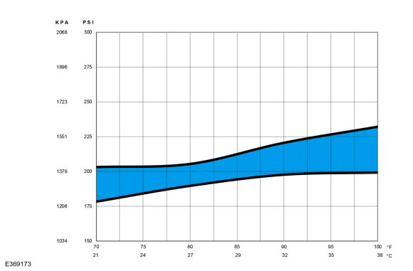
A/C
system, determine if the discharge pressure falls within the normal operating limits using the Normal Refrigerant Discharge Pressures 21 - 38 °C (70 - 100 °F) Ambient (30 - 60% Relative Humidity) chart below.
 |
-
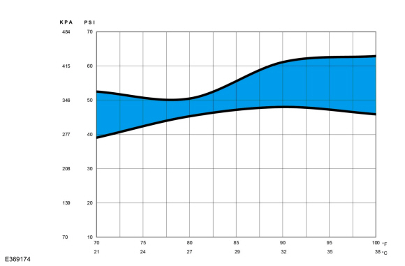
Determine if the suction pressure falls within the normal operating limits using the Normal Refrigerant Suction Pressures 21 - 38° C (70 - 100° F) Ambient (30 - 60% Relative Humidity) chart below.
 |
-
Record the suction pressure. If the pressure is fluctuating, record the average value.
-
NOTE: Use the following table to guide diagnosis of the refrigerant system if operating pressures are outside normal limits.
NOTE: The following table is meant to lead the technician in a diagnostic direction. It is not meant to be the final path to replacement of a component. Follow the Diagnostic and Testing (D&T) portion of the of the workshop manual (WSM) for actual final direction in circuit and component conditions found and actions taken.
High (Discharge) Pressure Low (Suction) Pressure Component — Causes High Normal to High - Condenser — inadequate airflow.
- Electrical Grill Shutter (if equipped) or Cooling Fan Improper function, Debris or blocked front end airflow.
- Engine — overheating.
Normal to High Normal - Refrigerant overcharge — air in refrigerant.
Normal to Low High - A/C Compressor — low performance, Check the EVDC compressor performance with the EVDC 100 control valve tester.
Normal to Low Normal to High - A/C suction line — partially restricted or plugged. a
Normal to Low Low - Low refrigerant charge — leak in system.
- A/C suction line — partially restricted or plugged. b
Normal to High Low Internally restricted condenser or receiver drier, IHX restriction (Suction Restriction). Normal to High High TXV not operating correctly, Not Closing. Normal to High Low TXV not operating correctly, Not Opening. Normal to Low Normal to Low Evaporator - Low or restricted air flow, Evaporator Temperature Sensor bad. Normal to Low Low Low refrigerant charge, A/C suction line Restricted. High Low IHX Line restricted (Liquid Line Restriction). Erratic Operation or Compressor Not Running - Ambient Air Temperature (OAT) (AAT) sensor — poor connection.
- A/C pressure transducer — poor connection.
- Evaporator temperature sensor — poor connection.
- Low refrigerant charge — leak in system.
- High Side Restrictions (Cycling) (condenser, liquid line/IHX line restriction, Reciever/Dryer restriction).
Additional Possible Components or Causes Associated With Inadequate Compressor Operation - Compressor drive belt — loose
- Compressor clutch — slipping
- Clutch coil open — shorted, or loose mounting
- Control assembly switch — dirty contacts or sticking open
- Clutch wiring circuit — high resistance, open or blown fuse
- Compressor operation interrupted by engine computer
Additional Possible Components or Causes Associated With a Damaged Compressor - Incorrect clutch air-gap
- Suction accumulator — refrigerant oil bleed hose plugged
- Refrigerant leaks
a Low pressure reading will be normal to high if restriction is downstream of service access valve.
b Low pressure reading will be low if restriction is upstream of service access valve.
Inspection
-
NOTE: Procedure 3 — Ambient Temperature Above 38 °C (100 °F)
Run the engine until it reaches normal operating temperature.
-
Connect the air conditioning service unit to the refrigerant system.
-
Set temperature to the lowest possible temperature
setting with the dual function disabled (if equipped). Manually set
blower on HI. If the vehicle has a fresh air/recirc button, set it to
FRESH. If the vehicle has an A/C switch or compressor on switch, set it to A/C ON.
-
Open all vehicle windows and leave the hood open for the
test. Open the rear hatch and/or rear doors (if equipped).
-
Confirm the compressor is operating and the engine
cooling fan(s) are operating or engaged. Allow the vehicle to idle until
the suction (low-side) and discharge (high-side) pressures are stable
or fluctuate in a range that repeats.
-
Record the ambient (shop) temperature.
-
Record the discharge pressure. If the pressure is fluctuating, record the average value.
-
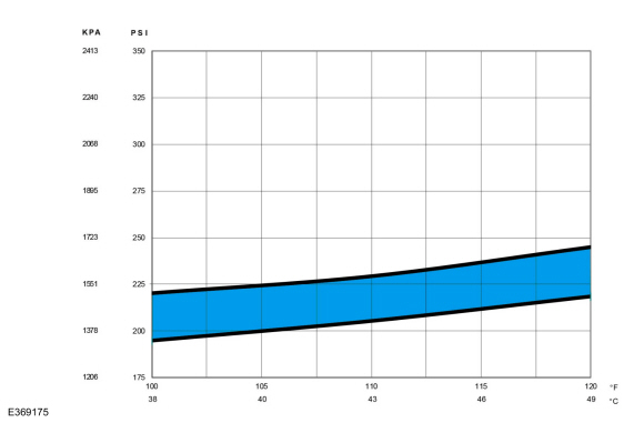
A/C
system, determine if the discharge pressure falls within the normal operating limits using the Normal Refrigerant Discharge Pressures 38 - 49 °C (100 - 120 °F) Ambient (15 - 40% Relative Humidity) chart below.
 |
-
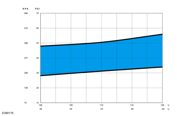
Determine if the suction pressure falls within the normal operating limits using the Normal Refrigerant Suction Pressures 38 - 49° C (100 - 120° F) Ambient (15 - 40% Relative Humidity) chart below.
 |
-
Record the suction pressure. If the pressure is fluctuating, record the average value.
-
NOTE: Use the following table to guide diagnosis of the refrigerant system if operating pressures are outside normal limits.
NOTE: The following table is meant to lead the technician in a diagnostic direction. It is not meant to be the final path to replacement of a component. Follow the Diagnostic and Testing (D&T) portion of the of the workshop manual (WSM) for actual final direction in circuit and component conditions found and actions taken.
High (Discharge) Pressure Low (Suction) Pressure Component — Causes High Normal to High - Condenser — inadequate airflow.
- Electrical Grill Shutter (if equipped) or Cooling Fan Improper function, Debris or blocked front end airflow.
- Engine — overheating.
Normal to High Normal - Refrigerant overcharge — air in refrigerant.
Normal to Low High - A/C Compressor — low performance, Check the EVDC compressor performance with the EVDC 100 control valve tester.
Normal to Low Normal to High - A/C suction line — partially restricted or plugged. a
Normal to Low Low - Low refrigerant charge — leak in system.
- A/C suction line — partially restricted or plugged. b
Normal to High Low Internally restricted condenser or receiver drier, IHX restriction (Suction Restriction). Normal to High High TXV not operating correctly, Not Closing. Normal to High Low TXV not operating correctly, Not Opening. Normal to Low Normal to Low Evaporator - Low or restricted air flow, Evaporator Temperature Sensor bad. Normal to Low Low Low refrigerant charge, A/C suction line Restricted. High Low IHX Line restricted (Liquid Line Restriction). Erratic Operation or Compressor Not Running - Ambient Air Temperature (OAT) (AAT) sensor — poor connection.
- A/C pressure transducer — poor connection.
- Evaporator temperature sensor — poor connection.
- Low refrigerant charge — leak in system.
- High Side Restrictions (Cycling) (condenser, liquid line/IHX line restriction, Reciever/Dryer restriction).
Additional Possible Components or Causes Associated With Inadequate Compressor Operation - Compressor drive belt — loose
- Compressor clutch — slipping
- Clutch coil open — shorted, or loose mounting
- Control assembly switch — dirty contacts or sticking open
- Clutch wiring circuit — high resistance, open or blown fuse
- Compressor operation interrupted by engine computer
Additional Possible Components or Causes Associated With a Damaged Compressor - Incorrect clutch air-gap
- Suction accumulator — refrigerant oil bleed hose plugged
- Refrigerant leaks
a Low pressure reading will be normal to high if restriction is downstream of service access valve.
b Low pressure reading will be low if restriction is upstream of service access valve.
 Refrigerant Oil Adding. General Procedures
Filling
Refer to the Refrigerant Oil Adding (when new components
are installed) chart below for refrigerant oil adding amounts and
methods of installation...
 Reset the Outside Air Temperature Sensor Learned Values. General Procedures
Configuration
NOTE:
The ambient air temperature sensor is a critical
component for correct Air Conditioning (A/C) and Heating, Ventilation,
and Air Conditioning (HVAC) system operation...
Other information:
Lincoln Navigator 2018-2026 Workshop Manual: Brake Disc. Removal and Installation
Materials Name Specification Motorcraft® Metal Brake Parts CleanerPM-4-A, PM-4-B, APM-4-C - Removal NOTE: Removal steps in this procedure may contain installation details. Remove the wheel and tire...
Lincoln Navigator 2018-2026 Workshop Manual: Thermostatic Expansion Valve Manifold and Tube Assembly. Removal and Installation
Special Tool(s) / General Equipment Flat Headed Screw Driver Locking Pliers Removal NOTICE: During the removal of components, cap, tape or otherwise appropriately protect all openings to prevent the ingress of dirt or other contamination...
Categories
- Manuals Home
- 4th Gen Lincoln Navigator Service Manual (2018 - 2026)
- Head Up Display (HUD) Module Calibration. General Procedures
- Neutral Flat Tow Activation and Deactivation. General Procedures
- Liftgate Trim Panel. Removal and Installation
- Front Bumper Cover. Removal and Installation
- SYNC Module [APIM]. Removal and Installation
Wheel to Hub Runout Minimization. General Procedures
Check
NOTE: Wheel-to-hub optimization is important. Clearance between the wheel and hub can be used to offset or neutralize the Road Force® or run-out of the wheel and tire assembly. For every 0.001 inch of wheel-to-hub clearance, the Road Force® can be affected between 1 and 3 pounds depending on the tire stiffness.
NOTE: The example below illustrates how the clearance between the wheel and the hub can be used to offset the high spot of radial run-out or Road Force®. Following the procedure will make sure of the best optimization.
Position the wheel and tire assembly on the vehicle so that the high spot location of radial run-out or Road Force® is at the 6 o'clock position and