Lincoln Navigator: Collision Warning and Collision Avoidance System / Head Up Display (HUD) Module Calibration. General Procedures
Special Tool(s) /
General Equipment
 |
501-418
Calibration Target - NO STEP File Available |
 |
501-419
Hud Eye Box |
Adjustment
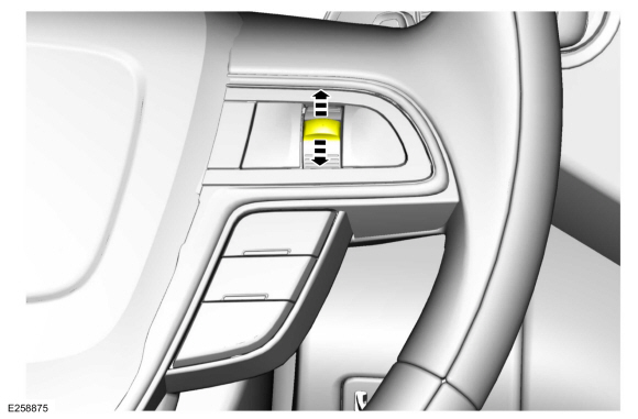
NOTE:
If it is necessary to cancel any calibration adjustment use the return button to cancel the current adjustment.
NOTE:
Typical application shown.
Positional calibration
-
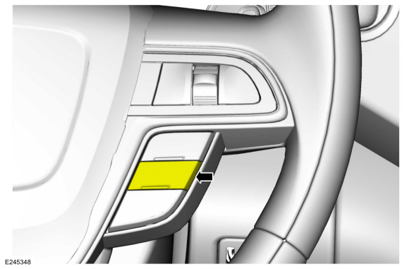
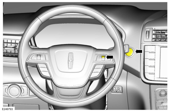
With brake pedal in the rest position, press the start button.
-
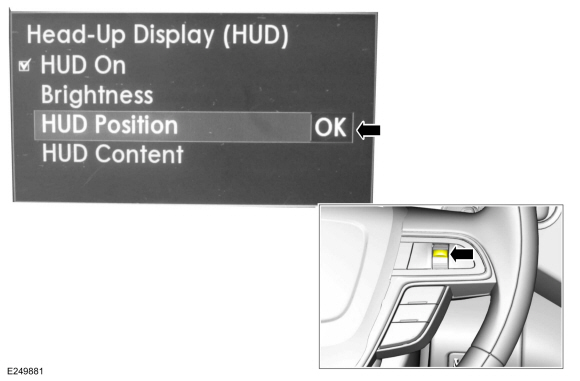
Select and press the HUD button.
-
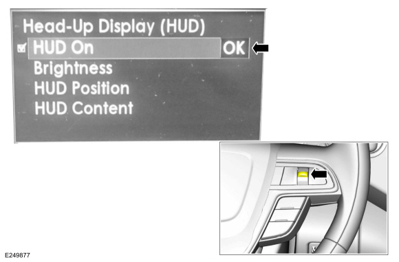
The instrument panel menu will appear in the message center and press OK.
-
Make sure the HUD is selected as ON.
-
With the brake pedal pressed, start the vehicle.
-
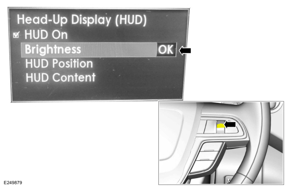
Select the brightness adjustment mode.
-
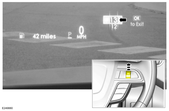
Set the HUD brightness to 13 and press OK.
-
Select the HUD position menu and press OK.
-
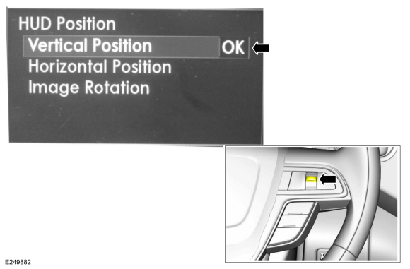
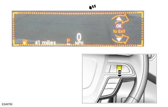
Select vertical position and press OK.
-
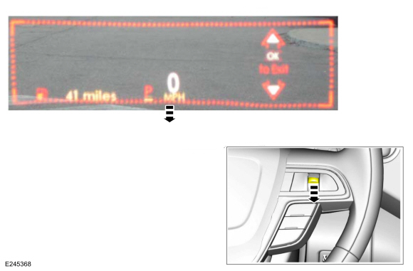
Move the vertical setting to the lowest position by
repeatedly selecting the down position on the control switch.
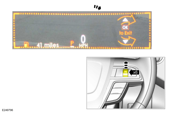
-
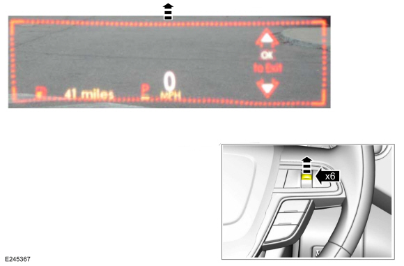
Vertically center the HUD by selecting the up position on the control switch six times.
-
Press OK.
-
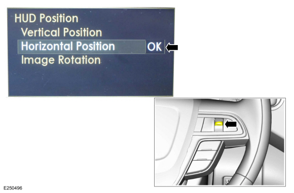
Select horizontal position and press OK.
-
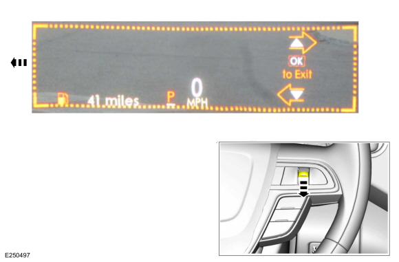
Move the horizontal setting to the leftmost position
by repeatedly selecting the down position on the control switch.
-
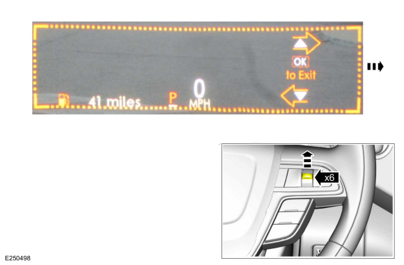
Horizontally center the HUD by selecting the up position on the control switch six times.
-
Press OK.
-
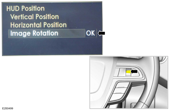
Select image rotation and press OK.
-
Move the rotational setting to the counter
clock-wise most position by repeatedly selecting the down position on
the control switch.
-
Rotationally center the HUD by selecting the up position on the control switch six times and press OK.
-
Press the OK button.
-
Turn the vehicle off.
Distortional calibration
-
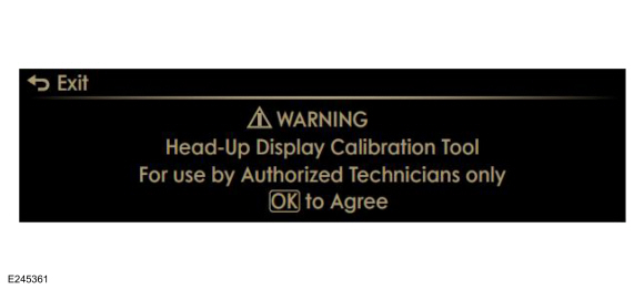
With brake pedal in the rest position, press and
hold the OK button, press the start button. and release the OK button
when the text "ETM" appears in the upper LH corner of the HUD .
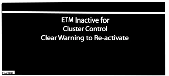
-
If there are any warnings in the instrument cluster
the ETM inactive screen will appear in the on windshield display.
-
NOTE:
If the OK button is pressed after all warnings are cleared the HUD will exit the ETM mode.
Press the OK button to clear each warning.
-
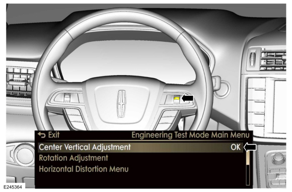
The HUD will display entry screen to the engineering test mode. Press
OK to enter the test mode or return to exit the test mode.
-
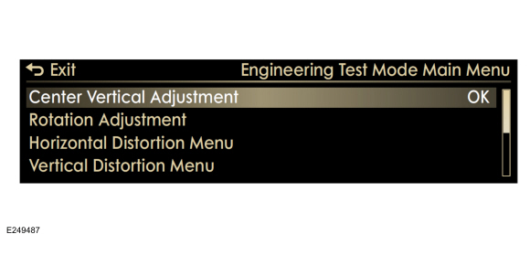
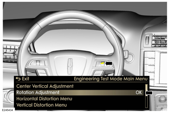
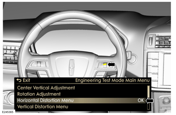
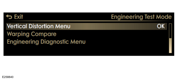
The HUD will display the test mode main menu.
-
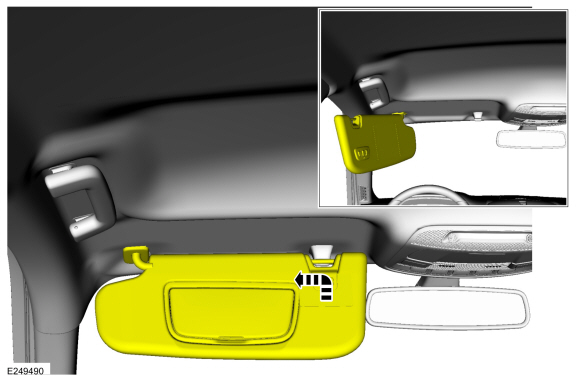
On both sides.
Raise the sunvisors and position them outward.
-
NOTE:
Typical application shown.
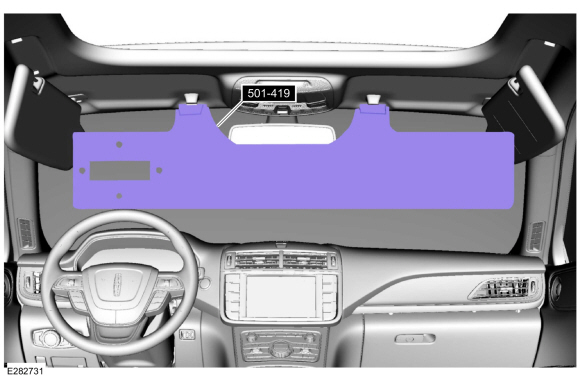
Set up the calibration tools.
-
Set up the calibration target. Position it level
and centered in the drivers view at the edge of the front bumper.
Use Special Service Tool: 501-418
Calibration Target - NO STEP File Available.
-
Install the HUD eye box.
Use Special Service Tool: 501-419
Hud Eye Box.
-
Select the center vertical adjustment menu item and press OK.
-
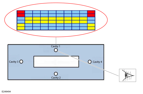
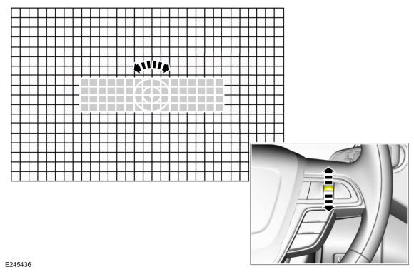
View the centering grid through the cavity 1 hole in the HUD eye box.
-
NOTE:
Skip this step if the top two boxes of the HUD adjustment grid are not seen.
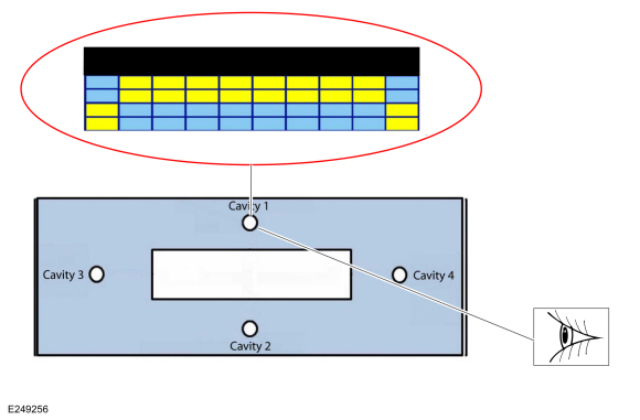
Adjust the alignment grid, using the up/down/OK
button on the steering wheel, while viewing the grid through cavity 1 in
the HUD eye box until the top two grid lines are not seen.
-
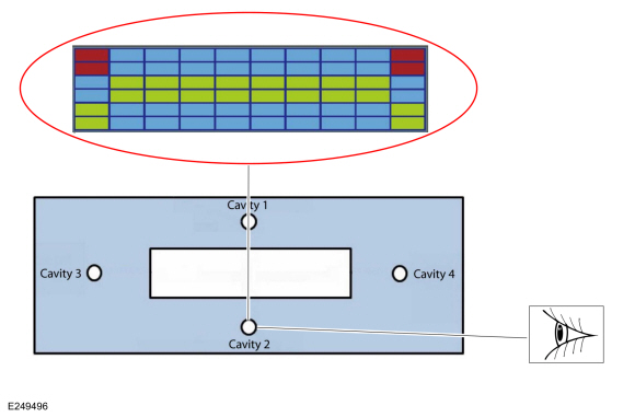
View the centering grid through the cavity 2 hole in the HUD eye box.
-
NOTE:
Skip this step if the bottom two boxes of the HUD adjustment grid are not seen.
Adjust the alignment grid while viewing the grid through cavity 2 in
the HUD eye box until the bottom two grid lines are not seen.
-
Press the OK button.
-
The rest of the adjustments for the HUD are carried out while being viewed through the large rectangular eye box opening.
-
Select the rotation adjustment menu item and press OK.
-
Adjust the alignment grid while viewing the grid through the HUD eye box until the grid is level and press OK.
-
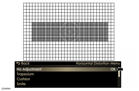
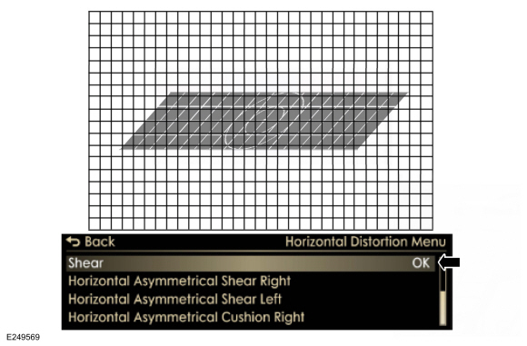
Select horizontal distortion adjustment menu and select OK.
-
NOTE:
Select trapezium and view grid.
Determine if horizontal distortion is present.
-
If no horizontal distortion is present select OK and go to step 44.
-
If horizontal distortion is present, go to step 40.
-
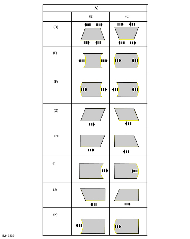
NOTE:
-
Horizontal
-
Selector lever UP
-
Selector lever DOWN
-
Trapezium
-
Cushion
-
Smile
-
Shear
-
Asymmetrical Shear Horizontal Right
-
Asymmetrical Cushion Horizontal Right
-
Asymmetrical Shear Horizontal Left
-
Asymmetrical Cushion Horizontal Left
Identify the category (D through K) for the most severe distortion present in the displayed image.
-
NOTE:
Steps for shear horizontal distortion shown, all other horizontal distortion steps are similar.
Select shear from the menu and press OK.
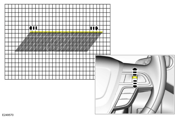
-
Using the up and down button remove the horizontal
distortion from the image then press OK to save adjustment.
-
Press return to exit to the previous menu.
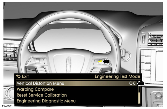
-
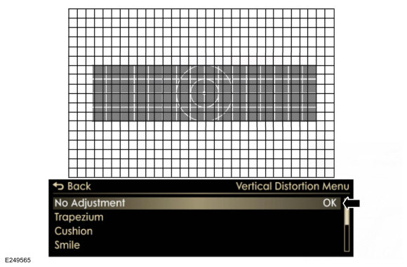
Select vertical distortion menu and press OK.
-
NOTE:
Select trapezium and view grid.
Determine if vertical distortion is present.
-
If no vertical distortion is present , go to step 50.
-
If vertical distortion is present, go to step 46.
-
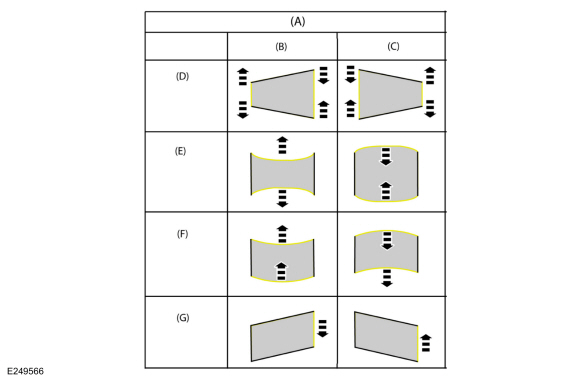
NOTE:
-
Vertical
-
Selector lever UP
-
Selector lever DOWN
-
Trapezium
-
Cushion
-
Smile
-
Shear
Identify the category of the most severe distortion present in the displayed image.
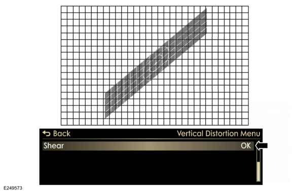
-
NOTE:
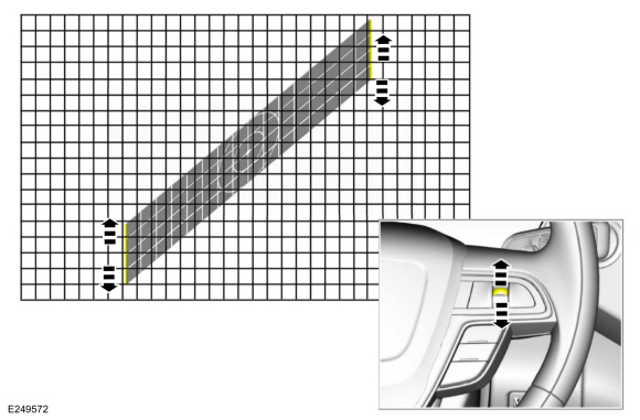
Steps for shear vertical distortion shown, all other vertical distortion steps are similar.
Select shear form the menu and press OK.
-
Using the up and down button remove the vertical distortion from the image then press OK.
-
Press return.
-
Carry out the warping compare procedure.
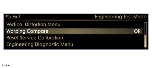
Warping compare
-
Select and press the back button item until the main menu is visible.
-
Select warping compare and press OK.
-
Using the up and down button cycle through the available displays.
-
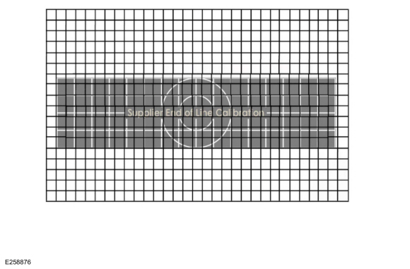
View and evaluate the supplier end of line calibration for warpage.
-
View and evaluate the calibration display. Carry out the actions below based on the display observed.
-
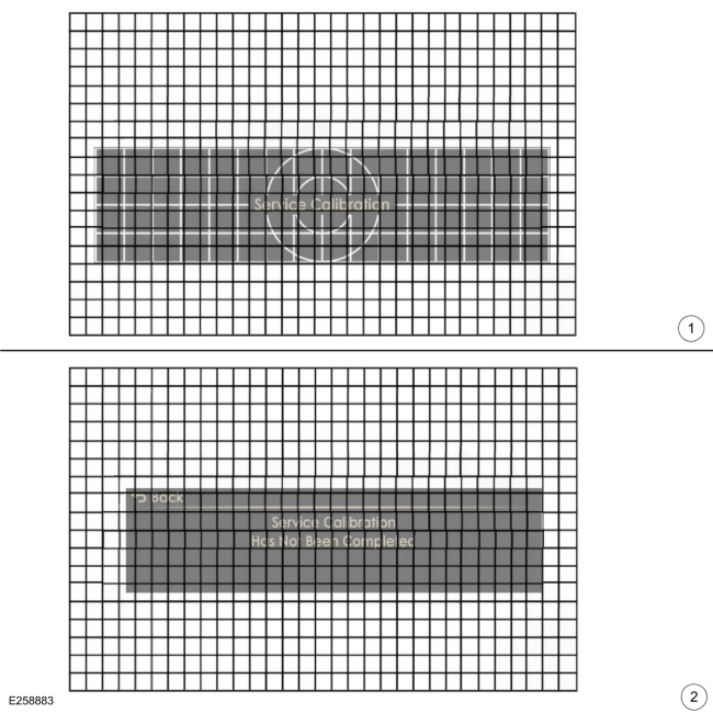
View and evaluate the service calibration for warpage.
-
Return to distortional calibration and complete service calibration.
-
View and evaluate the calibration display. Carry out the actions below based on the display observed.
-
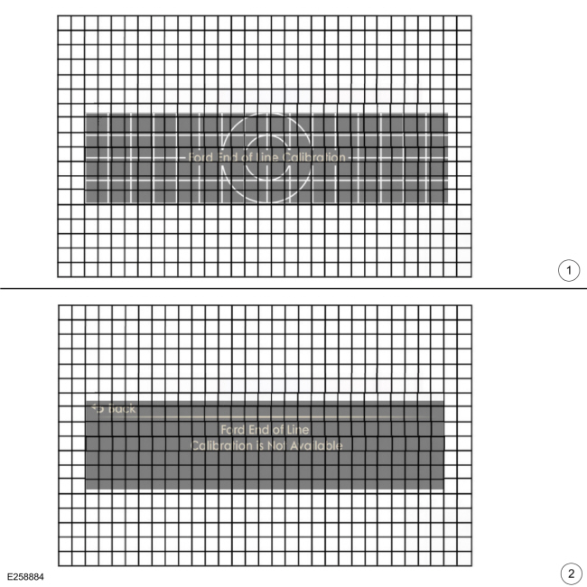
View and evaluate the Ford end of line calibration for warpage.
-
Disregard as an option for warpage improvement.
-
Review the grid in the HUD image and compare it to
the grid on the calibration target, switching between the different
warping corrections. Use this method to confirm the service warping
distortion correction improves the image quality over the end of line
warping. Did the service calibration correct the image distortion?
-
Yes: Exit the ETM mode and turn off the vehicle.
-
No: Carry out the service calibration reset procedure and start the distortion correction all over.
Service calibration reset
NOTE:
This procedure is to be used only when the positional and distortional
changes are to be erased and the HUD returned to the original factory
settings.
-
Press and hold the OK button, start the vehicle and release the HUD
button when the text "ETM" appears in the upper LH corner of the HUD .
-
If there are any warnings in the instrument cluster
the ETM inactive screen will appear in the on windshield display.
-
NOTE:
If the OK button is pressed after all warnings are cleared the HUD will exit the ETM mode.
Press the OK button to clear each warning.
-
The message center in the instrument cluster will
display entry screen to the engineering test mode. Press OK to enter the
test mode or return to exit the test mode.
-
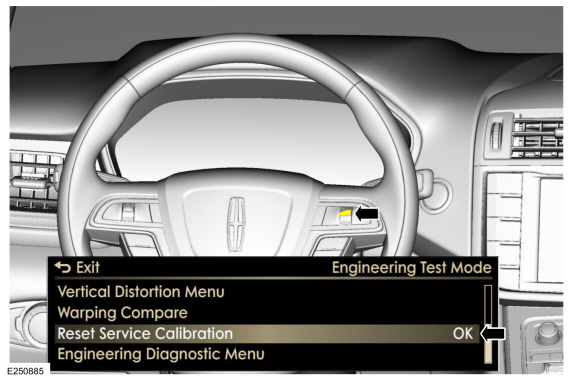
The message center will display the test mode main menu.
-
Select the Reset Service Calibration menu item and press OK.
-
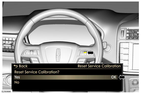
-
To reset the service calibration to the factory settings select YES and press OK.
-
To retain the current calibration settings select NO and press OK.
-
Press return.
-
Turn the vehicle off.
-
Remove the ETM visor.
DTC Charts
Diagnostics in this manual assume a certain skill level and knowledge of Ford-specific diagnostic practices. REFER to: Diagnostic Methods (100-00 General Information, Description and Operation)...
Removal
NOTE:
Removal steps in this procedure may contain installation details.
Remove the instrument panel.
Refer to: Instrument Panel (501-12 Instrument Panel and Console, Removal and Installation)...
Other information:
Diagnostic Trouble Code (DTC) Chart
Diagnostics in this manual assume a certain skill level and knowledge of Ford-specific diagnostic practices. REFER to: Diagnostic Methods (100-00 General Information, Description and Operation).
Module
DTC
Description
Action
PCM
P00FE:00
EVAP System Tank Vapor Line Restricted/Blocked: No Sub Type Information
GO to Pinpoint Test H..
Materials
Name
Specification
3M™ Super-Fast Repair Adhesive04747
-
Removal
NOTE:
Removal steps in this procedure may contain installation details.
NOTE:
If installing a new module, it is necessary to
upload the module configuration information to the diagnostic scan tool
prior to removing the module. This information must be downloa..

 Collision Warning and Collision Avoidance System. Diagnosis and Testing
 Head Up Display (HUD) Module. Removal and Installation
 205-1016
 205-153
(T80T-4000-W)
205-153
(T80T-4000-W)
 205-D061
(D83T-4205-C2)
205-D061
(D83T-4205-C2)