Lincoln Navigator: Side Panel Sheet Metal Repairs / B-Pillar Outer Panel. Removal and Installation
Special Tool(s) / General Equipment
| 6.5 mm Drill Bit | |
| Spherical Cutter | |
| Self-Piercing Rivet (SPR) Remover/Installer | |
| Belt Sander | |
| Blind Rivet Gun | |
| Air Body Saw | |
| MIG/MAG Welding Equipment | |
| Locking Pliers |
Materials
| Name | Specification |
|---|---|
| Metal Bonding Adhesive TA-1, TA-1-B, 3M™ 08115, LORD Fusor® 108B, Henkel Teroson EP 5055 |
- |
| Seam Sealer TA-2-B, 3M™ 08308, LORD Fusor® 803DTM |
- |
| Flexible Foam Repair 3M™ 08463, LORD Fusor® 121 |
- |
Removal
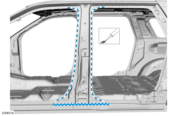
NOTICE: Body side sectioning is prohibited within 50mm of door hinge, door striker and restraints anchoring points.
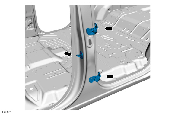
NOTE: LH side shown, RH side similar.
-
Depower the SRS .
Refer to: Supplemental Restraint System (SRS) Depowering (501-20B Supplemental Restraint System, General Procedures).
-
Verify the vehicle is dimensionally correct.
Refer to: Body and Frame (501-26 Body Repairs - Vehicle Specific Information and Tolerance Checks, Description and Operation).
-
Remove the rear door.
Refer to: Rear Door (501-03 Body Closures, Removal and Installation).
-
Remove the front door striker and rear door hinges at the body.
 |
-
Remove the front and rear door tread plates and door opening weather strips.
-
Remove the side curtain air bag.
Refer to: Side Curtain Airbag (501-20B Supplemental Restraint System, Removal and Installation).
-
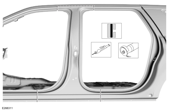
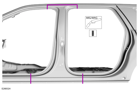
NOTE: Locate cutline along seam below roof ditch, this will allow for repair with roof panel intact.
Outer panel only
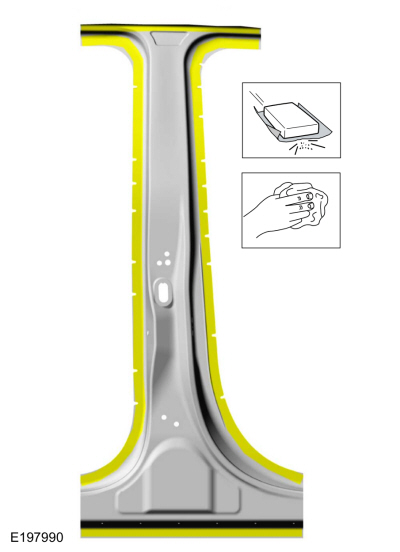
Carefully cut the outer panel only as indicated.
Use the General Equipment: Air Body Saw
Use the General Equipment: Spherical Cutter
 |
-
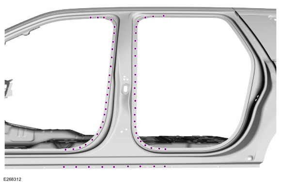
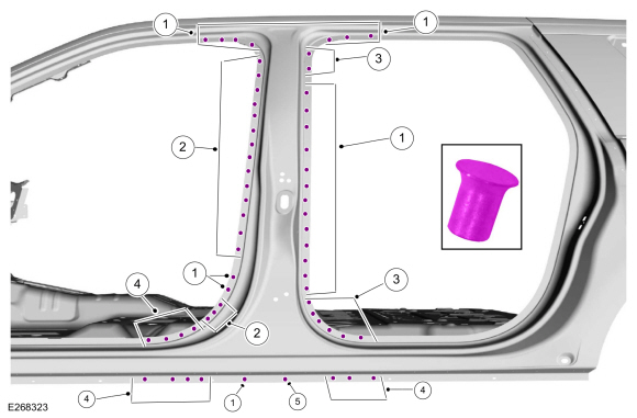
Remove the SPR fasteners.
Use the General Equipment: Self-Piercing Rivet (SPR) Remover/Installer
Use the General Equipment: Belt Sander
 |
-
NOTE: Aluminum body panels are highly receptive to heat transfer. With the extensive use of structural adhesives and non-structural sealers used in vehicle construction, the potential of heat transfer could impact adhesives and sealers in non-associated panels during the repair process. Many repairs areas that utilize structural adhesive may be separated after fastener removal by using a panel chisel along the joint/flange. Using heat not exceeding 425° F to loosen a bonded panel should only be done when all panels in the joint will be replaced and new adhesive applied.
Break the adhesive bond and remove the B-pillar outer panel.
 |
Installation
NOTICE: Body side sectioning is prohibited within 50mm of door hinge, door striker and restraints anchoring points.
NOTE: Do not install SPR fasteners directly in old SPR fastener location. SPR fasteners must be installed adjacent to the original location matching original quantity.
NOTE: Solid rivets or blind rivet fasteners may be used in place of SPR fasteners after enlarging existing holes to 6.5 mm.
-
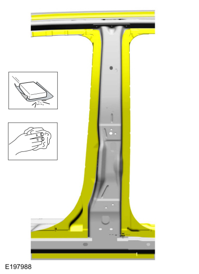
Sand using 80-120 grit sand paper to remove old adhesive and clean the B-pillar reinforcement mating surfaces.
 |
-
Cut the service panel to fit repair.
Use the General Equipment: Air Body Saw
Use the General Equipment: Spherical Cutter
 |
-
Sand using 80 grit sand paper to remove e-coat and clean the B-pillar service panel mating surfaces.
Material: Metal Bonding Adhesive / TA-1, TA-1-B, 3M™ 08115, LORD Fusor® 108B, Henkel Teroson EP 5055
 |
-
NOTE: The use of a backer plate when creating butt weld joints will produce a stronger and more uniform repair.
In butt-weld areas: create a backer plate from an unused portion of the old body panel or service replacement panel and install on the vehicle at each sectioning joint.
Refer to: Joining Techniques (501-25 Body Repairs - General Information, General Procedures).
-
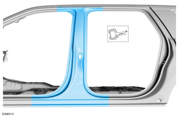
Apply adhesive to the body side flanges and NVH foam along rocker flange.
Material: Metal Bonding Adhesive / TA-1, TA-1-B, 3M™ 08115, LORD Fusor® 108B, Henkel Teroson EP 5055
Material: Flexible Foam Repair / 3M™ 08463, LORD Fusor® 121
 |
-
Install the service panel and clamp in position.
Use the General Equipment: Locking Pliers
|
-
Complete joining of service panel to backer plate and weld the sectioning seams using a MIG welder set up for aluminum.
Refer to: Joining Techniques (501-25 Body Repairs - General Information, General Procedures).
Use the General Equipment: MIG/MAG Welding Equipment
 |
-
NOTE: Do not install SPR fasteners directly in old SPR fastener location. SPR fasteners must be installed adjacent to the original location matching original quantity.
NOTE: Solid rivets or blind rivet fasteners may be used in place of SPR fasteners after enlarging existing holes to 6.5 mm.
Install fasteners.
Use the General Equipment: Self-Piercing Rivet (SPR) Remover/InstallerItem SPR Number SPR Code Henrob® Mandrel Pro-Spot® Mandrel Blind Rivet Solid Rivet Rivnut® 1 W708713-S900 AS DZ09-025/H SA-0400/SA-0401 - - - 2 W717184-S900 QA DP10-200/H SA-0400/SA-0402 - - - 3 W708717-S900 AW DG10-220/H SA-0400/SA-0402 - - - 4 W717186-S900 EN DP11-200/H SA-0400/SA-0402 - - - 5 W708717-S900 AW DP11-200/H SA-0400/SA-0402 - - -
 |
-
Drill 6.5 mm hole for blind rivet installation.
Use the General Equipment: 6.5 mm Drill Bit
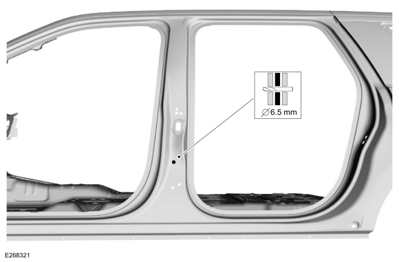 |
-
Install blind rivet fastener.
Use the General Equipment: Blind Rivet GunItem SPR Number SPR code Henrob® Mandrel Pro-Spot® Mandrel Blind Rivet Solid Rivet Rivnut® 1 - - - - W702512-S900C - -
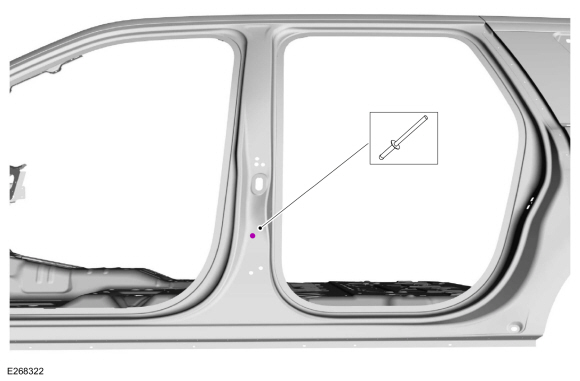 |
-
Metal finish using typical aluminum metal finishing techniques and a fiber-based body filler.
Refer to: Special Repair Considerations for Aluminum Repairs (501-25 Body Repairs - General Information, Description and Operation).
-
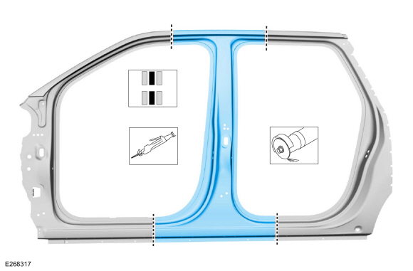
Sealing:
Repair area must be sealed to production level.
Material: Seam Sealer / TA-2-B, 3M™ 08308, LORD Fusor® 803DTM
-
Refinish the repair using a Ford approved paint system.
-
Install the side curtain air bag.
Refer to: Side Curtain Airbag (501-20B Supplemental Restraint System, Removal and Installation).
-
Install the front and rear door weather strips and scuff plates.
-
Install the front door striker and rear door hinges.
-
Front door striker.
Torque: 18 lb.ft (25 Nm)
-
Rear door hinges.
Torque: 22 lb.ft (30 Nm)
-
Front door striker.
|
-
Install and align the rear door.
Refer to: Rear Door (501-03 Body Closures, Removal and Installation).
Refer to: Rear Door Alignment (501-03 Body Closures, General Procedures).
-
Repower the SRS .
Refer to: Supplemental Restraint System (SRS) Repowering (501-20B Supplemental Restraint System, General Procedures).

 Front Door Skin Panel. Removal and Installation
Special Tool(s) /
General Equipment
6.5 mm Drill Bit
Grinder
Self-Piercing Rivet (SPR) Remover/Installer
Belt Sander
Blind Rivet Gun
Hot Air Gun
Knife
Locking Pliers
Materials
Name
Specification
Metal Bonding AdhesiveTA-1, TA-1-B, 3M™ 08115, LORD Fusor® 108B, Henkel Teroson EP 5055
-
Seam ..
Other information:
Lincoln Navigator 2018-2026 Workshop Manual: High-Pressure Fuel System. Diagnosis and Testing
Diagnostic Trouble Code (DTC) Chart Diagnostics in this manual assume a certain skill level and knowledge of Ford-specific diagnostic practices. REFER to: Diagnostic Methods (100-00 General Information, Description and Operation). Module DTC Description Action PCM P0001:00 Fuel Volume Regulator 'A' Control Circuit/Open: No Sub Type Information GO to Pinpoint Test H..
Lincoln Navigator 2018-2026 Workshop Manual: Driver Airbag. Removal and Installation
Removal WARNING: The following procedure prescribes critical repair steps required for correct restraint system operation during a crash. Follow all notes and steps carefully. Failure to follow step instructions may result in incorrect operation of the restraint system and increases the risk of serious personal injury or death in a crash. WARNING: ..
Categories
- Manuals Home
- 4th Gen Lincoln Navigator Service Manual (2018 - 2026)
- Transmission Fluid Level Check. General Procedures
- Rear View Mirrors - System Operation and Component Description. Description and Operation
- Power Running Board (PRB). Diagnosis and Testing
- Front Seat. Removal and Installation
- All Terrain Control Module (ATCM). Removal and Installation
Rear Camber Adjustment. General Procedures
Special Tool(s) / General Equipment
Wheel Alignment SystemActivation
NOTICE: Suspension fasteners are critical parts that affect the performance of vital components and systems. Failure of these fasteners may result in major service expense. Use the same or equivalent parts if replacement is necessary. Do not use a replacement part of lesser quality or substitute design. Tighten fasteners as specified.
Using alignment equipment and the manufacturer's instructions, measure the rear camber.Use the General Equipment: Wheel Alignment System