Lincoln Navigator: Side Panel Sheet Metal Repairs / B-Pillar and Reinforcement. Removal and Installation
Special Tool(s) / General Equipment
| 6.5 mm Drill Bit | |
| Polydrive Bit Socket | |
| Self-Piercing Rivet (SPR) Remover/Installer | |
| Belt Sander | |
| Blind Rivet Gun | |
| Hot Air Gun | |
| Locking Pliers |
Materials
| Name | Specification |
|---|---|
| Metal Bonding Adhesive TA-1, TA-1-B, 3M™ 08115, LORD Fusor® 108B, Henkel Teroson EP 5055 |
- |
Removal
NOTICE: Body side sectioning is prohibited within 50 mm of door hinge, door striker and restraints anchoring points.
NOTE: LH side shown, RH side similar.
-
Verify the vehicle is dimensionally correct.
Refer to: Body and Frame (501-26 Body Repairs - Vehicle Specific Information and Tolerance Checks, Description and Operation).
-
Remove the side curtain air bag.
Refer to: Side Curtain Airbag (501-20B Supplemental Restraint System, Removal and Installation).
-
Remove the front safety belt and safety belt height adjuster.
Refer to: Seatbelt Shoulder Height Adjuster (501-20A Seatbelt Systems, Removal and Installation).
-
Remove the rocker panel inner reinforcement.
Refer to: Rocker Panel Inner Reinforcement (501-29 Side Panel Sheet Metal Repairs, Removal and Installation).
-
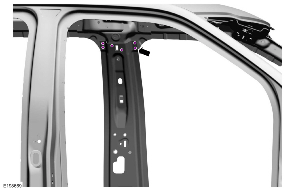
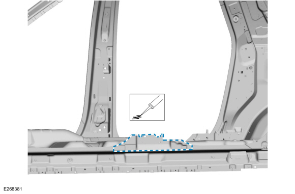
Remove the SPR fasteners.
Use the General Equipment: Self-Piercing Rivet (SPR) Remover/Installer
Use the General Equipment: Belt Sander
 |
-
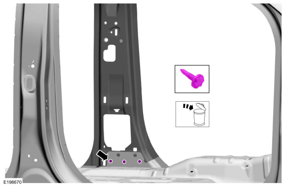
Remove and discard the FDS fasteners.
Use the General Equipment: Polydrive Bit Socket
 |
-
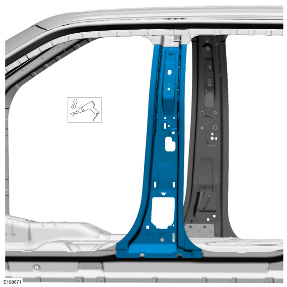
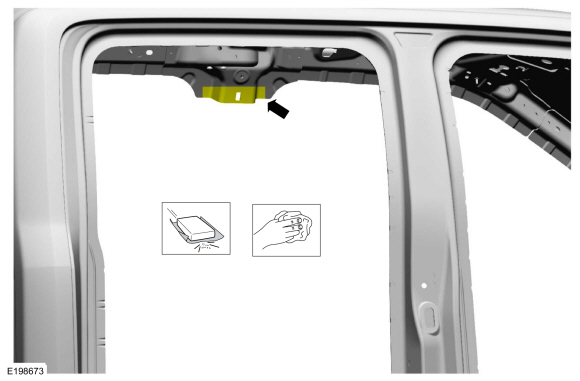
NOTE: Aluminum body panels are highly receptive to heat transfer. With the extensive use of structural adhesives and non-structural sealers used in vehicle construction, the potential of heat transfer could impact adhesives and sealers in non-associated panels during the repair process. Many repairs areas that utilize structural adhesive may be separated after fastener removal by using a panel chisel along the joint/flange. Using heat not exceeding 425° F to loosen a bonded panel should only be done when all panels in the joint will be replaced and new adhesive applied.
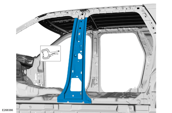
Break the adhesive bond and remove the B-pillar.
Use the General Equipment: Hot Air Gun
 |
Installation
NOTICE: Body side sectioning is prohibited within 50 mm of door hinge, door striker and restraints anchoring points.
NOTE: Do not install SPR fasteners directly in old SPR fastener location. SPR fasteners must be installed adjacent to the original location matching original quantity.
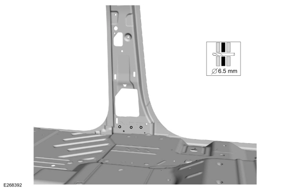
NOTE: Solid rivets or blind rivet fasteners may be used in place of SPR fasteners after enlarging existing holes to 6.5 mm.
NOTE: LH side shown, RH side similar.
-
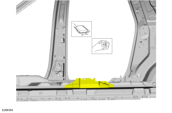
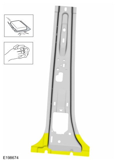
Sand using 80 grit sand paper to remove old adhesive and clean the B-pillar reinforcement lower mating surface.
 |
-
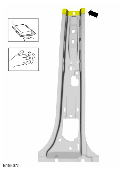
Sand using 80 grit sand paper to remove old adhesive and clean the B-pillar reinforcement upper mating surface.
 |
-
Sand using 80 grit sand paper to remove e-coat and clean the B-pillar service panel lower mating surface.
 |
-
Sand using 80 grit sand paper to remove e-coat and clean the B-pillar service panel upper mating surface.
 |
-
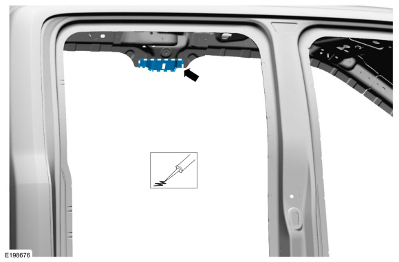
Apply adhesive.
Material: Metal Bonding Adhesive / TA-1, TA-1-B, 3M™ 08115, LORD Fusor® 108B, Henkel Teroson EP 5055
 |
-
Apply adhesive.
Material: Metal Bonding Adhesive / TA-1, TA-1-B, 3M™ 08115, LORD Fusor® 108B, Henkel Teroson EP 5055
 |
-
Install the B-pillar and clamp in position.
Use the General Equipment: Locking Pliers
 |
-
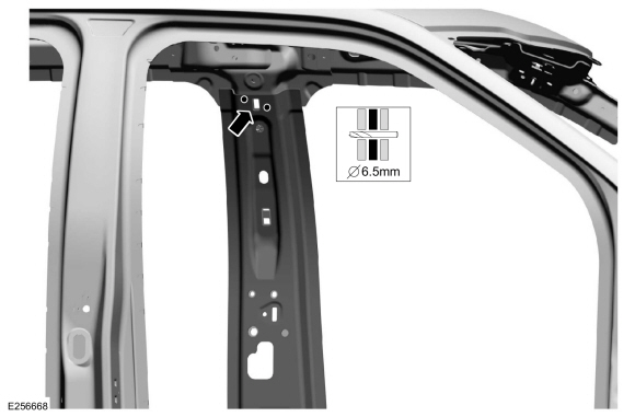
Drill for blind rivet fasteners.
Use the General Equipment: 6.5 mm Drill Bit
 |
-
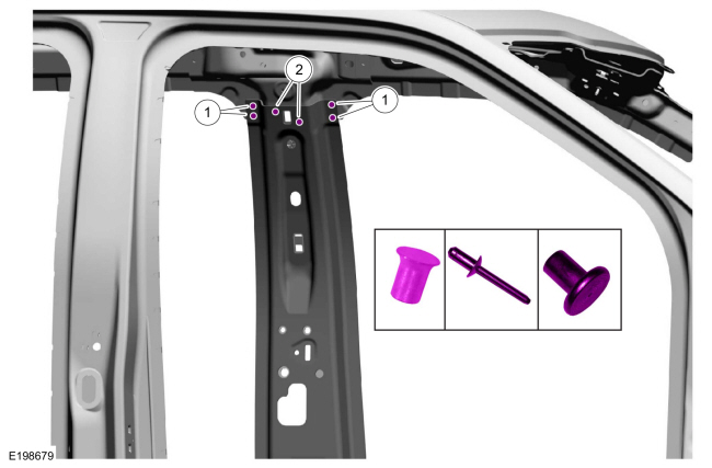
NOTE: Do not install SPR fasteners directly in old SPR fastener location. SPR fasteners must be installed adjacent to the original location matching original quantity.
NOTE: Solid rivets or blind rivet fasteners may be used in place of SPR fasteners after enlarging existing holes to 6.5 mm.
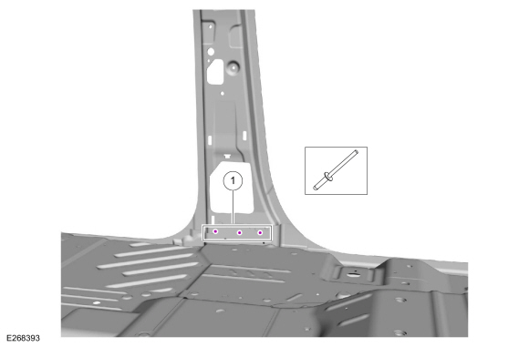
Install fasteners.Item SPR Number SPR Code Henrob® Mandrel Pro-Spot® Mandrel Blind Rivet Solid Rivet Rivnut® 1 W717186-S900 EN DG11-200/H SA-0400/SA-0401 - W790376-S900 - 2 - - - - W708777-S900C - -
Refer to: Joining Techniques (501-25 Body Repairs - General Information, General Procedures).
Use the General Equipment: Self-Piercing Rivet (SPR) Remover/Installer
Use the General Equipment: Blind Rivet Gun
 |
-
Drill 6.5 mm holes for blind rivet installation.
Use the General Equipment: 6.5 mm Drill Bit
 |
-
NOTE: Do not install SPR fasteners directly in old SPR fastener location. SPR fasteners must be installed adjacent to the original location matching original quantity.
NOTE: Solid rivets or blind rivet fasteners may be used in place of SPR fasteners after enlarging existing holes to 6.5 mm.
Install fasteners.Item SPR Number SPR Code Henrob® Mandrel Pro-Spot® Mandrel Blind Rivet Solid Rivet Rivnut® 1 - - - - W708777-S900C - -
Refer to: Joining Techniques (501-25 Body Repairs - General Information, General Procedures).
Use the General Equipment: Blind Rivet Gun
 |
-
Refinish using a Ford approved paint system and typical refinishing techniques.
-
Install the rocker panel reinforcement.
Refer to: Rocker Panel Inner Reinforcement (501-29 Side Panel Sheet Metal Repairs, Removal and Installation).
-
Install the side curtain air bag.
Refer to: Side Curtain Airbag (501-20B Supplemental Restraint System, Removal and Installation).
-
Install the front safety belt and safety belt height adjuster.
Refer to: Seatbelt Shoulder Height Adjuster (501-20A Seatbelt Systems, Removal and Installation).

 B-Pillar Outer Panel. Removal and Installation
Special Tool(s) /
General Equipment
6.5 mm Drill Bit
Spherical Cutter
Self-Piercing Rivet (SPR) Remover/Installer
Belt Sander
Blind Rivet Gun
Air Body Saw
MIG/MAG Welding Equipment
Locking Pliers
Materials
Name
Specification
Metal Bonding AdhesiveTA-1, TA-1-B, 3M™ 08115, LORD Fusor® 108B, Henkel Teroson EP 5..
Other information:
Lincoln Navigator 2018-2026 Workshop Manual: Second Row Seat Cushion Adjuster - Vehicles With: Multi-Contour Seats. Removal and Installation
Special Tool(s) / General Equipment Interior Trim Remover Removal NOTE: Right hand (RH) shown, left hand (LH) similar. Remove the second row single seat cover. Refer to: Second Row Single Seat Cushion Cover - Vehicles With: Multi-Contour Seats (501-10B Second Row Seats, Removal and Installation). Disconnect the second row sea..
Lincoln Navigator 2018-2026 Workshop Manual: Oil Pan. Removal and Installation
Special Tool(s) / General Equipment Plastic Scraper Oil Drain Equipment Vehicle/Axle Stands Materials Name Specification Motorcraft® High Performance Engine RTV SiliconeTA-357 WSE-M4G323-A6 Motorcraft® Silicone Gasket RemoverZC-30-A, AZC-30-C - Motorcraft® Metal Surface Prep WipesZC-31-B - M..
Categories
- Manuals Home
- 4th Gen Lincoln Navigator Service Manual (2018 - 2026)
- Telematics Control Unit (TCU) Module. Removal and Installation
- Body and Paint
- Identification Codes. Description and Operation
- Front Seat. Removal and Installation
- Front Bumper Cover. Removal and Installation
Wheel to Hub Runout Minimization. General Procedures
Check
NOTE: Wheel-to-hub optimization is important. Clearance between the wheel and hub can be used to offset or neutralize the Road Force® or run-out of the wheel and tire assembly. For every 0.001 inch of wheel-to-hub clearance, the Road Force® can be affected between 1 and 3 pounds depending on the tire stiffness.
NOTE: The example below illustrates how the clearance between the wheel and the hub can be used to offset the high spot of radial run-out or Road Force®. Following the procedure will make sure of the best optimization.
Position the wheel and tire assembly on the vehicle so that the high spot location of radial run-out or Road Force® is at the 6 o'clock position and