Lincoln Navigator: Third Row Seats / Third Row Single Seat Frame. Removal and Installation
Removal
 WARNING:
The following procedure describes critical repair steps
required for correct seat component installation. Follow all notes and
steps carefully. Do not place any objects between the seat components
and the body of the vehicle, nor any objects within a joint internal to
the seat structure. Failure to follow step instructions may result in
incorrect operation of the seat components and increases the risk of
serious personal injury.
WARNING:
The following procedure describes critical repair steps
required for correct seat component installation. Follow all notes and
steps carefully. Do not place any objects between the seat components
and the body of the vehicle, nor any objects within a joint internal to
the seat structure. Failure to follow step instructions may result in
incorrect operation of the seat components and increases the risk of
serious personal injury.
NOTE: Removal steps in this procedure may contain installation details.
-
Remove the third single row seat.
Refer to: Third Row Seat (501-10C Third Row Seats, Removal and Installation).
-
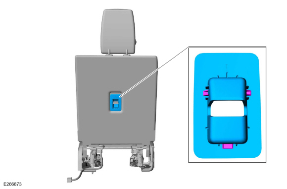
Remove the child safety seat tether anchor bezel.
 |
-
-
Release the third row single seat backrest cover J-clips.
-
Unzip the third row single seat backrest cover.
-
Position the third row single seat backrest cover flap aside.
-
Release the third row single seat backrest cover J-clips.
 |
-
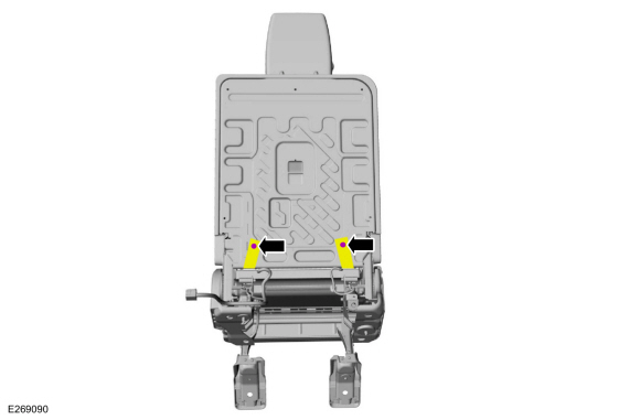
Remove the pin-type retainers and position the third row single seat backrest cover straps aside.
 |
-
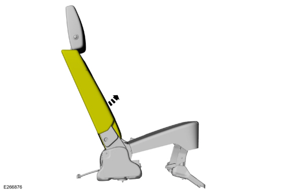
Lift the third row single seat backrest cover.
 |
-
On both sides.
Remove the screws and the third row single seat pivot arm covers.
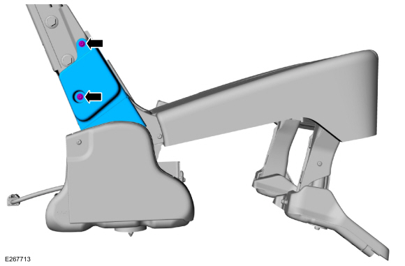 |
-
On both sides.
Remove the screws and the third row single seat pivot arm covers.
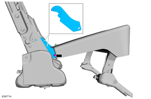 |
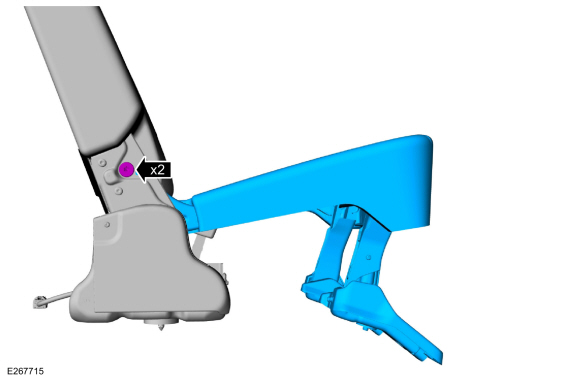
-
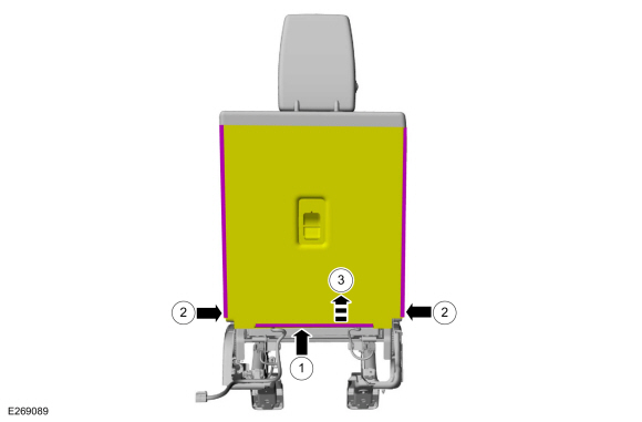
Remove the bolts and the third row single seat frame.
Torque: 33 lb.ft (45 Nm)
 |
-
NOTE: This step is only necessary when installing a new component.
Remove the third row single seat cushion cover.
Refer to: Third Row Single Seat Cushion Cover (501-10C Third Row Seats, Removal and Installation).
Installation
-
NOTE: Transfer components to the new third row single seat frame as necessary.
To install, reverse the removal procedures.
 Third Row Single Seat Cushion Cover. Removal and Installation
Removal
Remove the third row single seat.
Refer to: Third Row Seat (501-10C Third Row Seats, Removal and Installation).
Detach the third row single seat cushion cover J-clips...

Other information:
Lincoln Navigator 2018-2026 Workshop Manual: Power Fold Seat Control Switch. Removal and Installation
Special Tool(s) / General Equipment Flat-Bladed Screwdriver Interior Trim Remover Removal Vehicles with long wheelbase Remove the D-pillar trim panel. Refer to: D-Pillar Trim Panel - Long Wheelbase (501-05 Interior Trim and Ornamentation, Removal and Installation). Vehicles with short wheelbase Position the liftgate o..
Lincoln Navigator 2018-2026 Workshop Manual: Cruise Control. Diagnosis and Testing
Diagnostic Trouble Code (DTC) Chart Diagnostics in this manual assume a certain skill level and knowledge of Ford-specific diagnostic practices. REFER to: Diagnostic Methods (100-00 General Information, Description and Operation). Module DTC Description Action CCM B142E:78 Forward Looking Sensor Horizontal Alignment: Alignment Or Adjustment Incorrect GO to Pinpoint..
Categories
- Manuals Home
- 4th Gen Lincoln Navigator Service Manual (2018 - 2026)
- Transmission Fluid Drain and Refill. General Procedures
- Transmission Fluid Level Check. General Procedures
- Rear Bumper. Removal and Installation
- All Terrain Control Module (ATCM). Removal and Installation
- Brake Service Mode Activation and Deactivation. General Procedures
Rear Drive Axle and Differential. Diagnosis and Testing
Symptom Chart(s)
Diagnostics in this manual assume a certain skill level and knowledge of Ford-specific diagnostic practices.
REFER to: Diagnostic Methods (100-00 General Information, Description and Operation).
Symptom Chart - Differential
Symptom Chart - Differential
Condition Actions Axle overheating GO to Pinpoint Test A Broken gear teeth on the ring gear or pinion GO to Pi