Lincoln Navigator: Front Suspension - LHD 4WD / Lower Arm. Removal and Installation
Special Tool(s) / General Equipment
 |
204-592 Separator, Lower Arm Ball Joint TKIT-2006C-FFMFLM TKIT-2006C-LM TKIT-2006C-ROW |
Removal
NOTICE: Suspension fasteners are critical parts that affect the performance of vital components and systems. Failure of these fasteners may result in major service expense. Use the same or equivalent parts if replacement is necessary. Do not use a replacement part of lesser quality or substitute design. Tighten fasteners as specified.
-
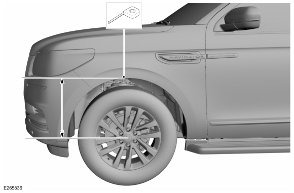
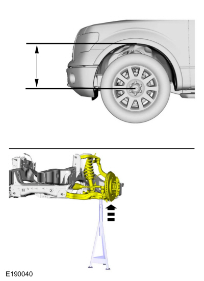
Measure the distance from the center of the hub to the
lip of the fender with the vehicle in a level, static ground position
(curb height).
 |
-
Remove the wheel and tire.
Refer to: Wheel and Tire (204-04A Wheels and Tires, Removal and Installation).
-
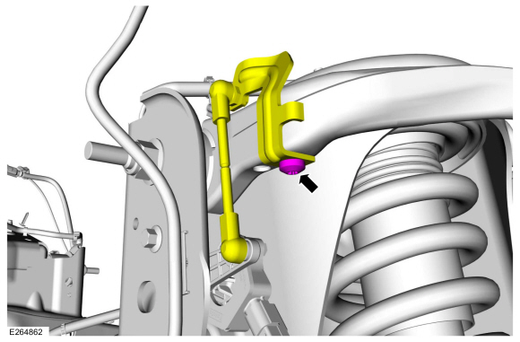
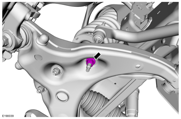
Remove the height sensor arm bracket screw and position aside the bracket.
 |
-
NOTICE: Do not use power tools to remove or install the stabilizer bar link nuts. Damage to the stabilizer bar link ball joints and boots may occur.
NOTE: The stabilizer bar links are designed with low friction ball joints that have a low breakaway torque.
NOTE: Use the hex-holding feature to prevent the ball stud from turning while removing or installing the stabilizer bar link nut.
Remove and discard the front stabilizer link lower nut.
 |
-
Remove and discard the shock absorber and spring assembly lower nuts.
 |
-
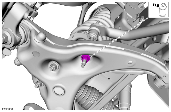
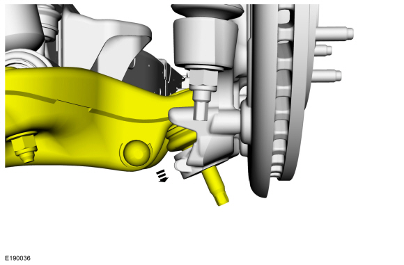
Remove and discard the lower ball joint nut.
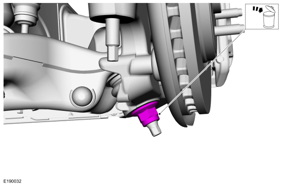 |
-
NOTICE: Do not use a prying device or separator fork between the ball joint and the wheel knuckle. Damage to the ball joint or ball joint seal may result.
NOTICE: Use care when releasing the lower arm and wheel knuckle into the resting position or damage to the ball joint seal may occur.
Separate the lower ball joint from the wheel knuckle.
Use Special Service Tool: 204-592 Separator, Lower Arm Ball Joint.
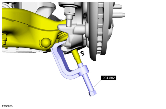 |
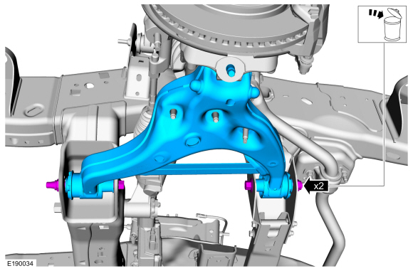
-
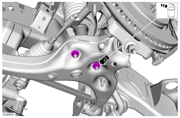
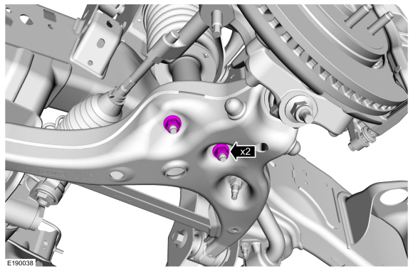
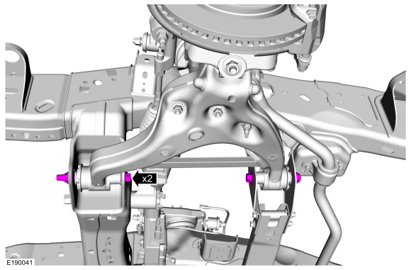
Remove and discard the lower arm bolts nuts and remove the lower arm.
 |
Installation
NOTICE: Tighten the suspension bushing fasteners with the suspension loaded or with the weight of the vehicle resting on the wheels and tires, otherwise incorrect clamp load and bushing damage may occur.
-
NOTE: Only tighten the nuts and bolts finger tight at this stage.
Position the lower arm and install the new lower arm bolts nuts.
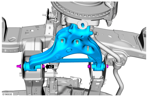 |
-
Attach the lower ball joint to the wheel knuckle.
 |
-
Install the new lower ball joint nut.
Torque: 76 lb.ft (103 Nm)
 |
-
Install the new shock absorber and spring assembly lower nuts.
Torque: 66 lb.ft (90 Nm)
 |
-
NOTICE: Do not use power tools to remove or install the stabilizer bar link nuts. Damage to the stabilizer bar link ball joints and boots may occur.
NOTE: The stabilizer bar links are designed with low friction ball joints that have a low breakaway torque.
NOTE: Use the hex-holding feature to prevent the ball stud from turning while removing or installing the stabilizer bar link nut.
Install the new front stabilizer link lower nut.
Torque: 59 lb.ft (80 Nm)
 |
-
Use a suitable jack to raise the suspension until the
distance between the center of the hub and the lip of the fender is
equal to the measurement taken during removal (curb height).
 |
-
NOTICE: Tighten the lower arm bolt and nuts with the weight of the vehicle on the wheels and tires or damage to the bushings may occur.
Tighten the new lower arm bolts nuts.
Torque: 258 lb.ft (350 Nm)
 |
-
Position the height sensor arm bracket and install the height sensor arm bracket screw.
Torque: 177 lb.in (20 Nm)
|
-
Install the wheel and tire.
Refer to: Wheel and Tire (204-04A Wheels and Tires, Removal and Installation).
-
Check and if necessary adjust front camber.
Refer to: Front Camber and Caster Adjustment (204-00 Suspension System - General Information, General Procedures).
-
Calibrate the suspension system. Connect the scan tool
and carry out the Ride Height Calibration routine. Follow the scan tool
directions.
 Front Wheel Bearing and Wheel Hub. Removal and Installation
Special Tool(s) /
General Equipment
Puller
Removal
NOTICE:
Suspension fasteners are critical parts that affect the
performance of vital components and systems...
 Lower Ball Joint. Removal and Installation
Special Tool(s) /
General Equipment
204-358Remover/Installer, Ball JointTKIT-2005P-FTKIT-2005P-ROW
205-086
(T74P-4635-C)
Installer/Remover, C-Frame and Screw
Removal
Remove the wheel knuckle...
Other information:
Lincoln Navigator 2018-2026 Workshop Manual: Axle Carrier Bushing. Removal and Installation
Special Tool(s) / General Equipment 204-186 (T95T-5638-AH) Remover, Front Differential Housing BushingTKIT-1995-FH/FLMHTKIT-1995-LMH/MH 204-187 (T95T-5638-BH) Installer, Front Differential Housing BushingTKIT-1995-FH/FLMHTKIT-1995-LMH/MH 205-289 (T89P-1249-A) Installer, Wheel Hub Dust SealTKIT-1988-FLMTKIT-1988-FTKIT-1989-LM 205-371 (T96T-..
Lincoln Navigator 2018-2026 Workshop Manual: D Clutch. Diagnosis and Testing
Symptom Chart D Clutch For D clutch operation, REFER to: D Clutch (307-01 Automatic Transmission - 10-Speed Automatic Transmission – 10R80, Description and Operation). D Clutch Condition Possible Sources Action D clutch does not apply SSD mechanically stuck OFF INSTALL a new sole..
Categories
- Manuals Home
- 4th Gen Lincoln Navigator Service Manual (2018 - 2026)
- Brake Service Mode Activation and Deactivation. General Procedures
- Vehicle Dynamics Control Module (VDM). Removal and Installation
- Front Seat. Removal and Installation
- Power Running Board (PRB). Diagnosis and Testing
- Rear View Mirrors - System Operation and Component Description. Description and Operation
Rear Camber Adjustment. General Procedures
Special Tool(s) / General Equipment
Wheel Alignment SystemActivation
NOTICE: Suspension fasteners are critical parts that affect the performance of vital components and systems. Failure of these fasteners may result in major service expense. Use the same or equivalent parts if replacement is necessary. Do not use a replacement part of lesser quality or substitute design. Tighten fasteners as specified.
Using alignment equipment and the manufacturer's instructions, measure the rear camber.Use the General Equipment: Wheel Alignment System