Lincoln Navigator: Front Suspension - LHD 4WD / Front Wheel Bearing and Wheel Hub. Removal and Installation
Special Tool(s) / General Equipment
| Puller |
Removal
NOTICE: Suspension fasteners are critical parts that affect the performance of vital components and systems. Failure of these fasteners may result in major service expense. Use the same or equivalent parts if replacement is necessary. Do not use a replacement part of lesser quality or substitute design. Tighten fasteners as specified.
-
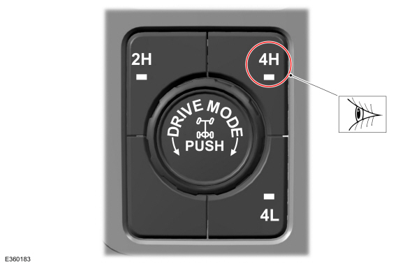
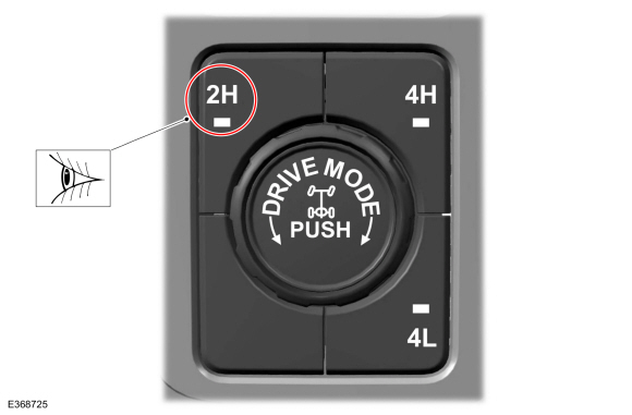
Select 4H on the ATCM .
 |
-
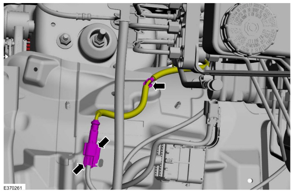
NOTE: The wheel speed sensor electrical connector is located in the engine compartment secured to the fender apron.
Disconnect the wheel speed sensor electrical connector and detach the harness retainer.
 |
-
Remove the wheel and tire.
Refer to: Wheel and Tire (204-04A Wheels and Tires, Removal and Installation).
-
-
NOTE: This step requires the aid of another technician.
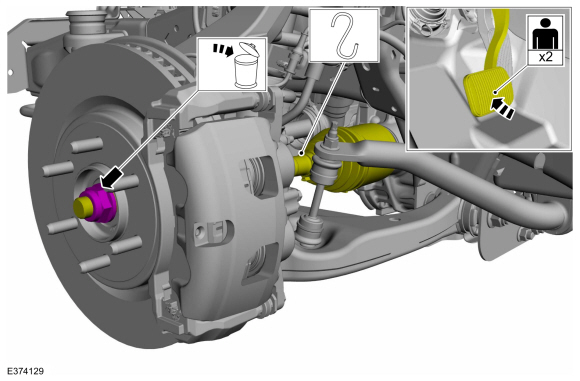
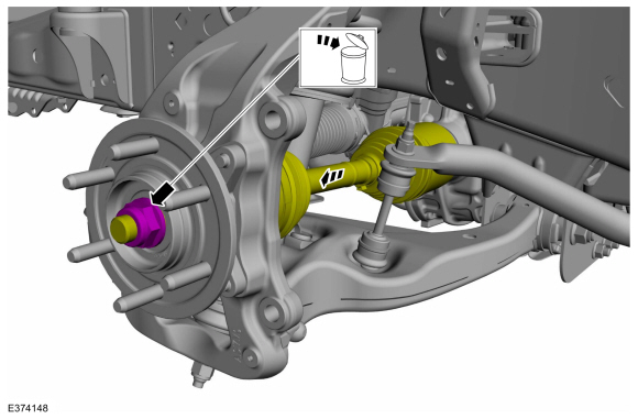
NOTE: Apply the brake to prevent the halfshaft from rotating while loosening the wheel hub nut.
Remove and discard the wheel hub nut.
-
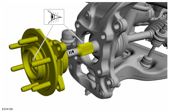
Using a general equipment, push the halfshaft into the wheel hub.
Use the General Equipment: Puller
-
Support the halfshaft assembly using mechanic's wire.
-
 |
-
Remove the brake disc shield.
Refer to: Brake Disc Shield (206-03 Front Disc Brake, Removal and Installation).
-
-
Remove the wheel speed sensor wire bracket bolt.
-
Remove the wheel speed sensor wire bracket bolt on
the wheel knuckle and position aside the wheel speed sensor wire.
-
Remove the wheel speed sensor wire bracket bolt.
 |
-
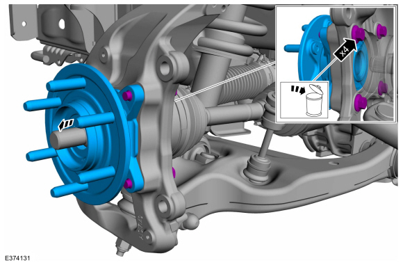
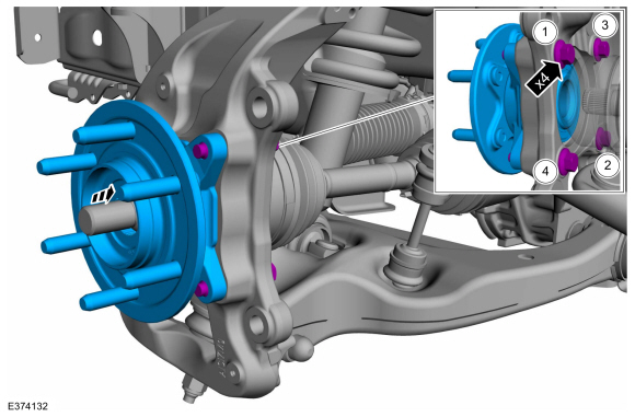
Remove and discard the 4 front wheel bearing and wheel
hub bolts and remove the front wheel bearing and wheel hub.
 |
Installation
NOTICE: Tighten the suspension fasteners with the weight of the vehicle on the wheels and tires or use a suitable jack to raise the suspension to curb height or damage to the bushings may occur.
-
Align the wheel hub splines to the front halfshaft splines to verify spline engagement.
 |
-
NOTICE: If the original wheel bearing and wheel hub is being installed, install a new wheel hub O-ring seal or damage to the wheel bearing may occur.
NOTE: Tighten the bolts in a cross pattern.
Position the front wheel bearing and wheel hub and install the 4 new front wheel bearing and wheel hub bolts.
Torque: 129 lb.ft (175 Nm)
 |
-
With old hub nut pull the halfshaft into the hub.
 |
-
-
Position the wheel speed sensor wire and install the wheel speed sensor wire bracket bolt.
Torque: 106 lb.in (12 Nm)
-
Install the wheel speed sensor wire bracket bolt on the wheel knuckle.
Torque: 18 lb.ft (25 Nm)
-
Position the wheel speed sensor wire and install the wheel speed sensor wire bracket bolt.
|
-
Install the brake disc shield.
Refer to: Brake Disc Shield (206-03 Front Disc Brake, Removal and Installation).
-
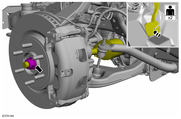
NOTICE: Install and tighten the new wheel hub nut to specification in a continuous rotation. Always install a new wheel hub nut after loosening or when not tightened to specification in a continuous rotation or damage to the components may occur.
NOTE: Apply the brake to keep the halfshaft from rotating.
While an assistant applies the brake, install the new wheel hub nut.
Torque: 184 lb.ft (250 Nm)
 |
-
Install the wheel and tire.
Refer to: Wheel and Tire (204-04A Wheels and Tires, Removal and Installation).
-
NOTE: The wheel speed sensor electrical connector is located in the engine compartment secured to the fender apron.
Connect the wheel speed sensor electrical connector and the harness retainer.
|
-
Select 2H on the ATCM .
 |
 Front Stabilizer Bar Link. Removal and Installation
Removal
NOTICE:
Suspension fasteners are critical parts that affect the
performance of vital components and systems. Failure of these fasteners
may result in major service expense...
 Lower Arm. Removal and Installation
Special Tool(s) /
General Equipment
204-592Separator, Lower Arm Ball JointTKIT-2006C-FFMFLMTKIT-2006C-LMTKIT-2006C-ROW
Removal
NOTICE:
Suspension fasteners are critical parts that affect the
performance of vital components and systems...
Other information:
Lincoln Navigator 2018-2026 Workshop Manual: Low Voltage Differential Signalling (LVDS) Cable. Removal and Installation
Removal Remove the APIM . Refer to: Information and Entertainment System - Component Location (415-00 Information and Entertainment System - General Information - Vehicles With: SYNC 4, Description and Operation). Remove the FDIM ...
Lincoln Navigator 2018-2026 Workshop Manual: Satellite Radio / Global Positioning System (GPS) Splitter / Cable. Removal and Installation
Removal NOTE: Removal steps in this procedure may contain installation details. Remove the ACM . Refer to: Information and Entertainment System - Component Location (415-00 Information and Entertainment System - General Information - Vehicles With: SYNC 4, Description and Operation)...
Categories
- Manuals Home
- 4th Gen Lincoln Navigator Service Manual (2018 - 2026)
- SYNC Module [APIM]. Removal and Installation
- All Terrain Control Module (ATCM). Removal and Installation
- Identification Codes. Description and Operation
- Front Seat. Removal and Installation
- Head Up Display (HUD) Module Calibration. General Procedures
Wheel to Hub Runout Minimization. General Procedures
Check
NOTE: Wheel-to-hub optimization is important. Clearance between the wheel and hub can be used to offset or neutralize the Road Force® or run-out of the wheel and tire assembly. For every 0.001 inch of wheel-to-hub clearance, the Road Force® can be affected between 1 and 3 pounds depending on the tire stiffness.
NOTE: The example below illustrates how the clearance between the wheel and the hub can be used to offset the high spot of radial run-out or Road Force®. Following the procedure will make sure of the best optimization.
Position the wheel and tire assembly on the vehicle so that the high spot location of radial run-out or Road Force® is at the 6 o'clock position and