Lincoln Navigator: Power Steering / Tie Rod. Removal and Installation
Special Tool(s) / General Equipment
| Boot Clamp Pliers |
Materials
| Name | Specification |
|---|---|
| Motorcraft® Premium Long-Life Grease XG-1-E1 |
ESA-M1C75-B |
Removal
-
Remove the tie rod end.
Refer to: Tie Rod End (211-02 Power Steering, Removal and Installation).
-
Remove the tie rod end jamb nut.
 |
-
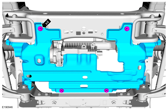
NOTE: If equipped.
Remove the underbody shield retainers and remove the underbody shield.
 |
-
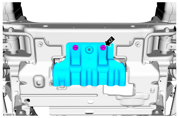
NOTE: If equipped.
Remove the underbody shield retainers and remove the underbody shield.
 |
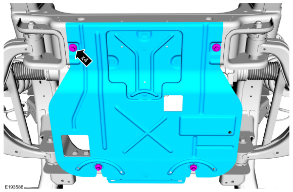
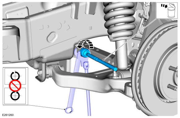
-
NOTE: If equipped.
NOTE: 4WD (four-wheel drive) shown, RWD (rear wheel drive) similar.
Remove the underbody shield bolts and the underbody shield.
 |
-
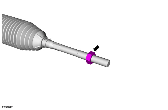
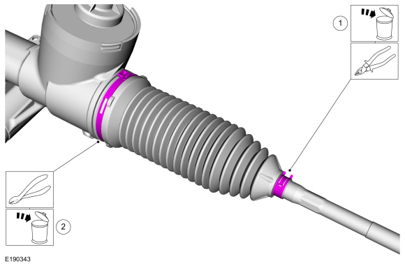
NOTE: If servicing the RH (right-hand) tie rod, both bellows boots must be removed.
-
Remove and discard the inner bellows boot clamp.
-
Remove and discard the outer bellows boot clamp.
-
Remove and discard the inner bellows boot clamp.
 |
-
NOTE: If servicing the RH (right-hand) tie rod, both bellows boots must be removed.
NOTE: Move the bellows boot enough to gain access to the inner tie rod nut.
Position aside the bellows boot.
 |
-
Position the steering rack far enough to the LH side to expose the flat surface.
 |
-
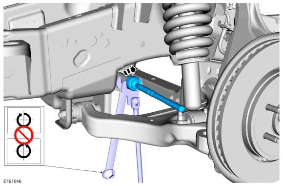
NOTICE: Place the steering gear at the center position and hold the steering gear rack while loosening the inner tie rod. Use an appropriate-sized wrench on the flat/teeth of the rack to resist rotation and to prevent damage during removal of the inner tie rod.
NOTE: The steering gear rack can only be held on the LH (left-hand) side.
Using an appropriate-sized wrench on the flat/teeth to hold the rack and an appropriate size crows foot wrench or open end wrench, remove and discard the inner tie rod.
 |
Installation
-
NOTICE: Place the steering gear at the center position and hold the steering gear rack while tightening the inner tie rod. Use an appropriate-sized wrench on the flat/teeth of the rack to resist rotation and to prevent damage during installation of the inner tie rod.
NOTE: The help of an assistant may be necessary to torque the RH (right-hand) inner tie rod.
Using an appropriate-sized wrench on the flat/teeth to hold the rack and an appropriate size crows foot wrench or open end wrench, install the inner tie rod.
Torque: 89 lb.ft (120 Nm)
 |
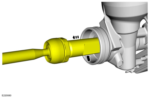
-
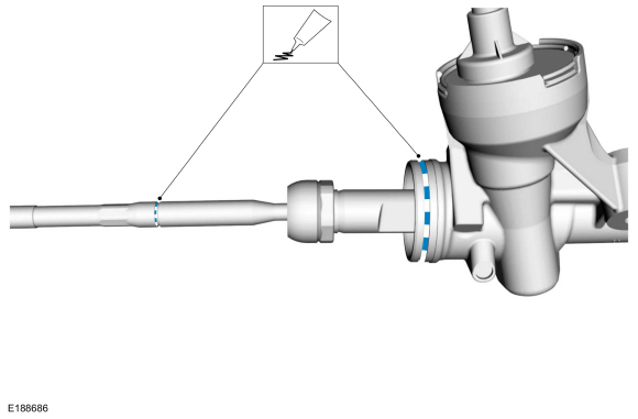
Apply the specified grease to the steering
gear-to-bellows boot mating surface and bellows boot groove on the inner
tie-rod.
Material: Motorcraft® Premium Long-Life Grease / XG-1-E1 (ESA-M1C75-B)
 |
-
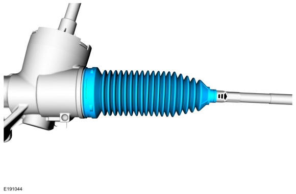
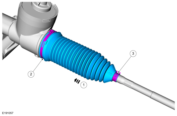
NOTE: LH (left-hand) side shown, RH (right-hand) side similar.
-
NOTE: Make sure the steering gear bellows boot is positioned correctly over the steering gear housing bead and the groove in the inner tie rod.
Install the new steering gear bellows boot.
-
Install the new inner bellows boot clamp.
Use the General Equipment: Boot Clamp Pliers
-
Install the new outer bellows boot clamp.
-
 |
-
NOTE: If equipped.
NOTE: 4WD (four-wheel drive) shown, RWD (rear wheel drive) similar.
Install the underbody shield and the underbody shield retainers.
Torque: 30 lb.ft (40 Nm)
|
-
NOTE: If equipped.
Install the underbody shield and install the underbody shield retainers.
Torque: 30 lb.ft (40 Nm)
|
-
NOTE: If equipped.
Install the underbody shield and install the underbody shield retainers.
Torque: 30 lb.ft (40 Nm)
|
-
Thread the tie-rod end jam nut onto the inner tie rod.
|
-
Install the tie rod end.
Refer to: Tie Rod (211-02 Power Steering, Removal and Installation).
 Steering Gear Boot. Removal and Installation
Special Tool(s) /
General Equipment
Boot Clamp Pliers
Materials
Name
Specification
Motorcraft® Premium Long-Life GreaseXG-1-E1
ESA-M1C75-B
Removal
Remove the tie-rod end...
 Tie Rod End. Removal and Installation
Special Tool(s) /
General Equipment
Tie Rod End Remover
Removal
NOTE:
Removal steps in this procedure may contain installation details...
Other information:
Lincoln Navigator 2018-2026 Workshop Manual: Fuel Filler Door Assembly. Removal and Installation
Special Tool(s) / General Equipment Flat Headed Screw Driver Knife Removal NOTE: Removal steps in this procedure may contain installation details. NOTE: The fuel filler door assembly is damaged during the removal process and requires a new fuel filler door assembly installed...
Lincoln Navigator 2018-2026 Workshop Manual: Pyrotechnic Device Disposal. General Procedures
Disposal Disposal of Deployable Devices and Pyrotechnic Devices That Are Undeployed-Inoperative NOTE: All inoperative airbags, seatbelt pretensioners and inflatable seatbelt inflators have been placed on the Mandatory Return List. Treat all discolored or damaged airbags the same as any inoperative live airbag being returned...
Categories
- Manuals Home
- 4th Gen Lincoln Navigator Service Manual (2018 - 2026)
- Telematics Control Unit (TCU) Module. Removal and Installation
- Windshield Washer Pump. Removal and Installation
- Power Running Board (PRB). Diagnosis and Testing
- Body Control Module (BCM). Removal and Installation
- Transmission Fluid Level Check. General Procedures
Axle Tube Bearing. Removal and Installation
Special Tool(s) / General Equipment
 205-123
(T78P-1177-A)
205-123
(T78P-1177-A)
Installer, Axle Shaft Oil Seal
 308-047
(T77F-1102-A)
308-047
(T77F-1102-A)
Remover, Bearing Cup Slide Hammer