Lincoln Navigator: Power Steering / Tie Rod End. Removal and Installation
Special Tool(s) / General Equipment
| Tie Rod End Remover |
Removal
NOTE: Removal steps in this procedure may contain installation details.
-
NOTICE: Disconnect the battery ground cable anytime the steering linkage is being serviced or damage to the steering gear may occur resulting in steering gear replacement.
Disconnect the battery ground cable.
Refer to: Battery Disconnect and Connect (414-01 Battery, Mounting and Cables, General Procedures).
-
Remove the wheel and tire.
Refer to: Wheel and Tire (204-04A Wheels and Tires, Removal and Installation).
-
-
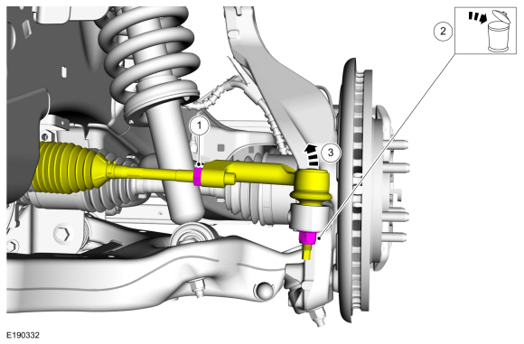
Loosen the tie rod end jam nut.
Torque: 76 lb.ft (103 Nm)
-
NOTE: Use the hex-holding feature to prevent the stud from turning while removing the nut.
Remove and discard the outer tie rod end nut.
Torque: 66 lb.ft (90 Nm)
-
NOTICE: Do not use a hammer to separate the outer tie-rod end from the wheel knuckle or damage to the wheel knuckle may result.
NOTICE: Use care when installing the tie rod separator or damage to the outer tie-rod end boot may occur.
Separate the outer tie rod end from the wheel spindle.
Use the General Equipment: Tie Rod End Remover
-
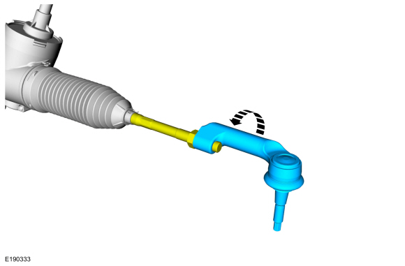
Loosen the tie rod end jam nut.
 |
-
NOTE: Count and record the number of turns required to remove the outer tie-rod end for reference during installation.
Remove the tie rod end.
 |
Installation
-
To install, reverse the removal procedure.
-
Check and if necessary, adjust front toe.
Refer to: Front Toe Adjustment (204-00 Suspension System - General Information, General Procedures).
 Tie Rod. Removal and Installation
Special Tool(s) /
General Equipment
Boot Clamp Pliers
Materials
Name
Specification
Motorcraft® Premium Long-Life GreaseXG-1-E1
ESA-M1C75-B
Removal
Remove the tie rod end...

Other information:
Lincoln Navigator 2018-2026 Workshop Manual: Front Stabilizer Bar. Removal and Installation
Removal NOTICE: Suspension fasteners are critical parts that affect the performance of vital components and systems. Failure of these fasteners may result in major service expense. Use the same or equivalent parts if replacement is necessary. Do not use a replacement part of lesser quality or substitute design. Tighten fasteners as specified. NOTE: Removal steps in this proc..
Lincoln Navigator 2018-2026 Workshop Manual: Catalytic Converter LH. Removal and Installation
Special Tool(s) / General Equipment 303-476 (T94P-9472-A) Socket, Exhaust Gas Oxygen SensorTKIT-1994-LM/MTKIT-1994-FTKIT-1994-FLM/FM Materials Name Specification Motorcraft® High Temperature Nickel Anti-Seize LubricantXL-2 - Motorcraft® Penetrating and Lock LubricantXL-1 - Removal NOTE: If the catalytic conver..
Categories
- Manuals Home
- 4th Gen Lincoln Navigator Service Manual (2018 - 2026)
- All Terrain Control Module (ATCM). Removal and Installation
- Windshield Washer Pump. Removal and Installation
- Rear Bumper. Removal and Installation
- Brake Service Mode Activation and Deactivation. General Procedures
- Front Bumper Cover. Removal and Installation
Front Driveshaft. Removal and Installation
Special Tool(s) / General Equipment
Crimping ToolMaterials
Name Specification Motorcraft® Premium Long-Life GreaseXG-1-E1 ESA-M1C75-B
Removal
With the vehicle in NEUTRAL, position the vehicle on a hoist.Refer to: Jacking and Lifting (100-02 Jacking and Lifting, Description and Operation).
Remove the bolts and the transmission shield.