Lincoln Navigator: Driveshaft / Front Driveshaft. Removal and Installation
Special Tool(s) / General Equipment
| Crimping Tool |
Materials
| Name | Specification |
|---|---|
| Motorcraft® Premium Long-Life Grease XG-1-E1 |
ESA-M1C75-B |
Removal
-
With the vehicle in NEUTRAL, position the vehicle on a hoist.
Refer to: Jacking and Lifting (100-02 Jacking and Lifting, Description and Operation).
-
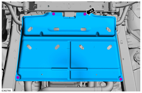
Remove the bolts and the transmission shield.
 |
-
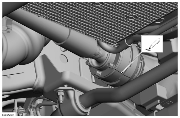
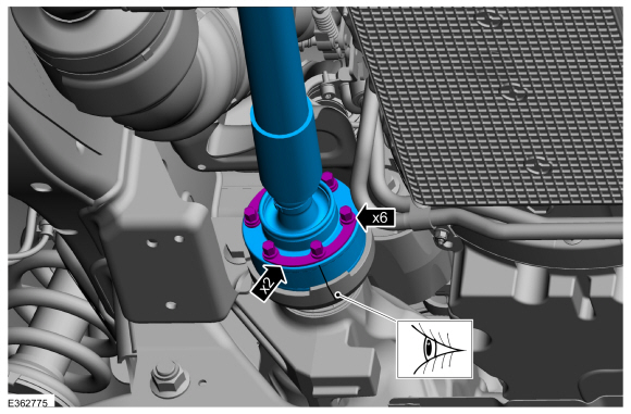
Index-mark the front driveshaft flange CV joint to the pinion flange cup.
 |
-
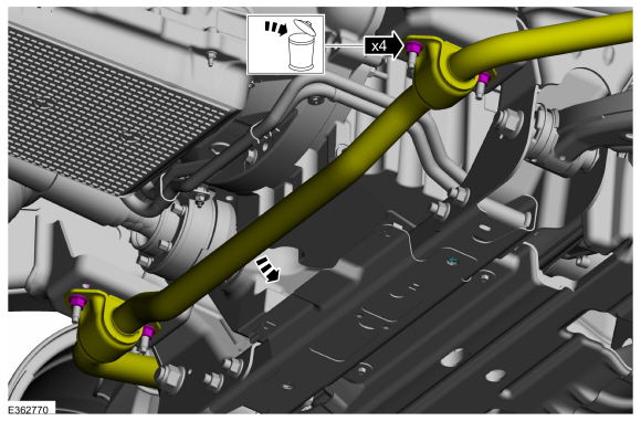
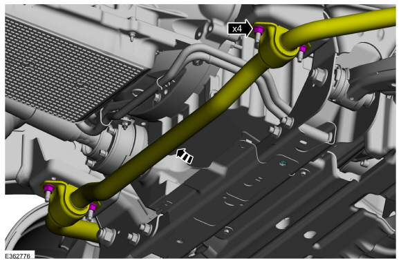
Remove and discard the stabilizer bar bracket nuts and allow the stabilizer bar to swing downward.
 |
-
-
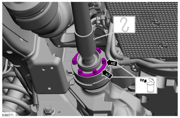
Remove and discard the front driveshaft CV joint-to-pinion flange cup bolts and retaining straps.
-
Support the front driveshaft.
-
Remove and discard the front driveshaft CV joint-to-pinion flange cup bolts and retaining straps.
 |
-
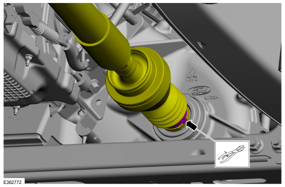
Remove the front driveshaft slip yoke boot clamp at transfer case end.
Use the General Equipment: Crimping Tool
 |
-
NOTE: Care should be taken not to damage the driveshaft splines.
-
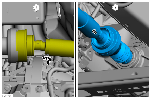
Remove the front driveshaft from pinion flange and allow it to move rearward.
-
Pull and remove the front driveshaft from transfer case.
-
Remove the front driveshaft from pinion flange and allow it to move rearward.
 |
Installation
-
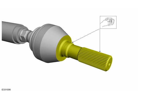
Clean and inspect the boot. If required replace the boot.
-
NOTE: Make sure that the mating faces are clean and free of foreign material.
Clean the debris or contamination of the splines.
 |
-
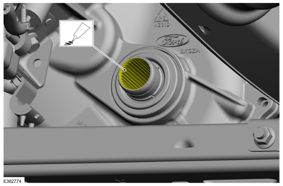
Lubricate the transfer case plug-on yoke splines with grease.
Material: Motorcraft® Premium Long-Life Grease / XG-1-E1 (ESA-M1C75-B)
 |
-
Insert the front driveshaft into the transfer case plug-on yoke and secure the boot clamp.
Use the General Equipment: Crimping Tool
|
-
NOTE: Make sure that new components are installed.
-
Align the index-mark on the driveshaft and pinon flange.
-
Fit the driveshaft into the drive pinion flange.
-
Install the new front driveshaft CV joint-to-pinion flange cup retaining straps and bolts.
Torque: 41 lb.ft (55 Nm)
-
Align the index-mark on the driveshaft and pinon flange.
 |
-
NOTE: Make sure that new nuts are installed.
Swing the stabilizer bar upward and install the new stabilizer bar bracket nuts.
Torque: 46 lb.ft (63 Nm)
 |
-
Install the transmission shield and the bolts.
Torque: 71 lb.in (8 Nm)
|
 Driveshaft Runout and Balancing. General Procedures
Special Tool(s) /
General Equipment
100-002
(TOOL-4201-C)
Holding Fixture with Dial Indicator Gauge
Inspection
NOTE:
Driveline vibration exhibits a higher frequency and lower
amplitude then high-speed shake...
 Rear Driveshaft. Removal and Installation
Special Tool(s) /
General Equipment
Flat Headed Screw Driver
Tire Lever
Removal
All vehicles
With the vehicle in NEUTRAL, position it on a hoist...
Other information:
Lincoln Navigator 2018-2026 Workshop Manual: Rear Blower Motor Speed Control. Removal and Installation
Removal NOTE: Removal steps in this procedure may contain installation details. Remove the RH loadspace trim panel. Refer to: Loadspace Trim Panel (501-05 Interior Trim and Ornamentation, Removal and Installation). Disconnect the blower motor speed control electrical connectors...
Lincoln Navigator 2018-2026 Workshop Manual: Evaporative Emission Canister Purge Valve. Removal and Installation
Removal WARNING: Do not smoke, carry lighted tobacco or have an open flame of any type when working on or near any fuel-related component. Highly flammable mixtures may be present and may be ignited. Failure to follow these instructions may result in serious personal injury...
Categories
- Manuals Home
- 4th Gen Lincoln Navigator Service Manual (2018 - 2026)
- Transmission Fluid Drain and Refill. General Procedures
- Neutral Flat Tow Activation and Deactivation. General Procedures
- Vehicle Dynamics Control Module (VDM). Removal and Installation
- Brake Service Mode Activation and Deactivation. General Procedures
- Body Control Module (BCM). Removal and Installation
Wheel to Hub Runout Minimization. General Procedures
Check
NOTE: Wheel-to-hub optimization is important. Clearance between the wheel and hub can be used to offset or neutralize the Road Force® or run-out of the wheel and tire assembly. For every 0.001 inch of wheel-to-hub clearance, the Road Force® can be affected between 1 and 3 pounds depending on the tire stiffness.
NOTE: The example below illustrates how the clearance between the wheel and the hub can be used to offset the high spot of radial run-out or Road Force®. Following the procedure will make sure of the best optimization.
Position the wheel and tire assembly on the vehicle so that the high spot location of radial run-out or Road Force® is at the 6 o'clock position and