Lincoln Navigator: Driveshaft / Rear Driveshaft. Removal and Installation
Special Tool(s) / General Equipment
| Flat Headed Screw Driver | |
| Tire Lever |
Removal
All vehicles
-
With the vehicle in NEUTRAL, position it on a hoist.
Refer to: Jacking and Lifting (100-02 Jacking and Lifting) .
-
-
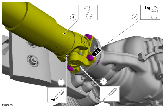
Index-mark the driveshaft flange to the pinion flange to maintain alignment during installation.
-
Remove and discard the driveshaft flange to pinion flange bolts.
Torque: 76 lb.ft (103 Nm)
-
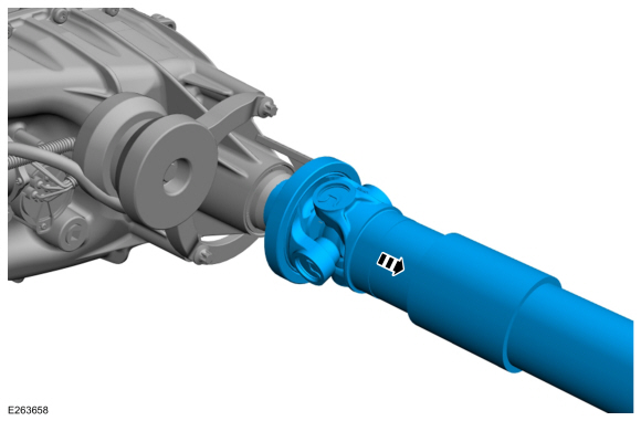
NOTICE: The driveshaft flange fits tightly on the flange pilot. Never hammer on the driveshaft or any of its components to disconnect the driveshaft flange from the flange pilot. Pry only in the area shown with a suitable tool, to disconnect the driveshaft flange from the flange pilot or damage to the driveshaft flange can occur.
Using a large flat headed screwdriver or tire lever, separate the driveshaft flange from the pinion flange.
Use the General Equipment: Flat Headed Screw Driver
Use the General Equipment: Tire Lever
-
Support the driveshaft.
-
Index-mark the driveshaft flange to the pinion flange to maintain alignment during installation.
 |
Vehicles equipped with a 4 bolt style yoke
-
-
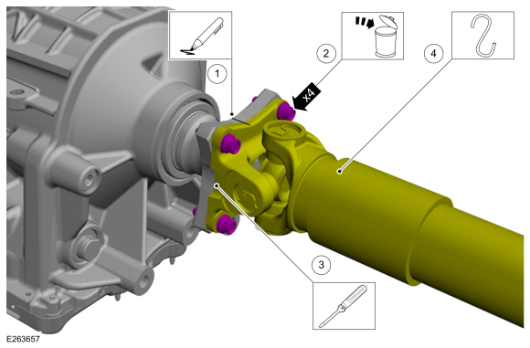
Index-mark the driveshaft flange to the transmission flange to maintain alignment during installation.
-
NOTICE: The driveshaft flange fits tightly on the pinion flange pilots. To make sure that the driveshaft flanges seat squarely on the pinion flange pilots, tighten the driveshaft flange bolts evenly in a cross pattern or damage to the flanges can occur.
Remove and discard the driveshaft flange to transmission flange bolts.
Torque: 76 lb.ft (103 Nm)
-
NOTICE: The driveshaft flange fits tightly on the flange pilot. Never hammer on the driveshaft or any of its components to disconnect the driveshaft flange from the flange pilot. Pry only in the area shown with a suitable tool, to disconnect the driveshaft flange from the flange pilot or damage to the driveshaft flange can occur.
NOTE: The driveshaft flange to transmission flange is a tight fit. It may be necessary to remove the center bearing bolts before the driveshaft flange will separate from the transmission flange.
Using a large flat headed screwdriver or tire lever, separate the driveshaft flange from the transmission flange.
Use the General Equipment: Flat Headed Screw Driver
Use the General Equipment: Tire Lever
-
Support the driveshaft.
-
Index-mark the driveshaft flange to the transmission flange to maintain alignment during installation.
 |
-
NOTE: Make sure a new nut and bolt is installed.
If equipped with a two piece driveshaft.
-
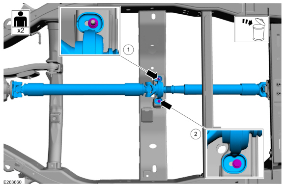
Remove and discard the driveshaft center bearing nut.
Torque: 35 lb.ft (48 Nm)
-
Remove and discard the driveshaft center bearing bolt and remove the driveshaft.
Torque: 35 lb.ft (48 Nm)
-
Remove and discard the driveshaft center bearing nut.
 |
-
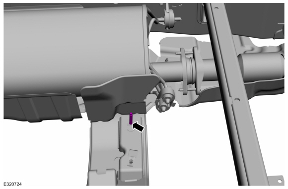
NOTE: Make sure that new a stud is installed.
Remove and discard the driveshaft center bearing bracket mounting stud.
 |
Vehicles equipped with a slip yoke
-
Remove the driveshaft.
 |
Installation
-
To install, reverse the removal procedure.
-
If equipped with a slip yoke, check the transfer case fluid.
Refer to: Transfer Case Draining and Filling (308-07 Transfer Case) .
 Front Driveshaft. Removal and Installation
Special Tool(s) /
General Equipment
Crimping Tool
Materials
Name
Specification
Motorcraft® Premium Long-Life GreaseXG-1-E1
ESA-M1C75-B
Removal
With the vehicle in NEUTRAL, position the vehicle on a hoist...
 Driveshaft Universal Joint. Disassembly and Assembly
Special Tool(s) /
General Equipment
205-086
(T74P-4635-C)
Installer/Remover, C-Frame and Screw
Vise
Materials
Name
Specification
Motorcraft® Premium Long-Life GreaseXG-1-E1
ESA-M1C75-B
DISASSEMBLY
NOTICE:
Do not, under any circumstance, clamp the driveshaft
assembly in the jaws of a vise or similar holding fixture...
Other information:
Lincoln Navigator 2018-2026 Workshop Manual: Running Board Control Module (RBM). Removal and Installation
Removal NOTE: Removal steps in this procedure may contain installation details. Remove the steering column opening trim panel. Remove the bolts and the steering column reinforcement panel...
Lincoln Navigator 2018-2026 Workshop Manual: Wheel Knuckle. Removal and Installation
Special Tool(s) / General Equipment 204-592/1Adapter for 204-592 Removal NOTICE: Suspension fasteners are critical parts that affect the performance of vital components and systems. Failure of these fasteners may result in major service expense...
Categories
- Manuals Home
- 4th Gen Lincoln Navigator Service Manual (2018 - 2026)
- Telematics Control Unit (TCU) Module. Removal and Installation
- Body Control Module (BCM). Removal and Installation
- Body and Paint
- Identification Codes. Description and Operation
- Rear Bumper. Removal and Installation
Rear Camber Adjustment. General Procedures
Special Tool(s) / General Equipment
Wheel Alignment SystemActivation
NOTICE: Suspension fasteners are critical parts that affect the performance of vital components and systems. Failure of these fasteners may result in major service expense. Use the same or equivalent parts if replacement is necessary. Do not use a replacement part of lesser quality or substitute design. Tighten fasteners as specified.
Using alignment equipment and the manufacturer's instructions, measure the rear camber.Use the General Equipment: Wheel Alignment System