Lincoln Navigator: Driveshaft / Driveshaft Universal Joint. Disassembly and Assembly
Special Tool(s) / General Equipment
 |
205-086
(T74P-4635-C)
Installer/Remover, C-Frame and Screw |
| Vise | |
Materials
| Name | Specification |
|---|---|
| Motorcraft® Premium Long-Life Grease XG-1-E1 |
ESA-M1C75-B |
DISASSEMBLY
NOTICE: Do not, under any circumstance, clamp the driveshaft assembly in the jaws of a vise or similar holding fixture. Denting or localized fracturing may result, causing driveshaft failure during vehicle operation.
NOTE: This procedure is intended to be used for all U-joints with snap ring retainers.
-
Remove the driveshaft.
Refer to: Rear Driveshaft (205-01 Driveshaft, Removal and Installation).
-
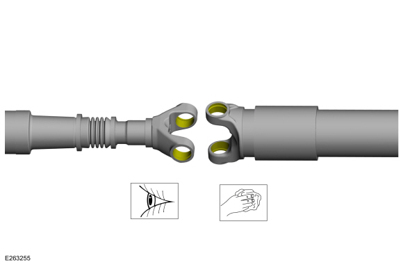
NOTE: If the components are not marked and therefore installed incorrectly, driveshaft imbalance can occur.
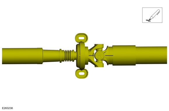
NOTE: Center bearing U-joint shown, others similar.
Index-mark the driveshaft for reassembly.
 |
-
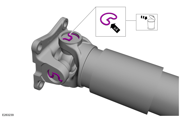
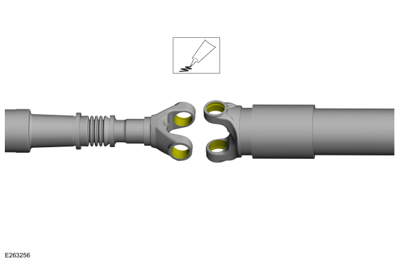
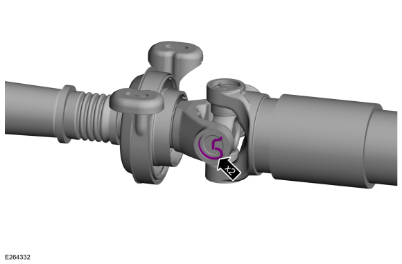
NOTE: Center bearing U-joint shown, others similar.
Remove and discard the snap rings.
 |
-
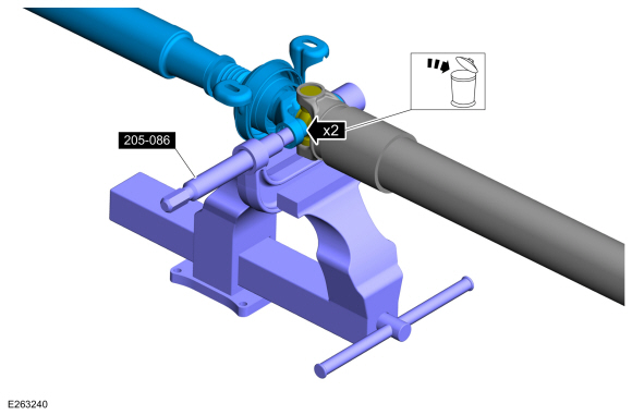
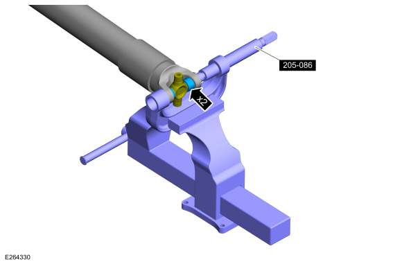
NOTE: Center bearing U-joint shown, others similar.
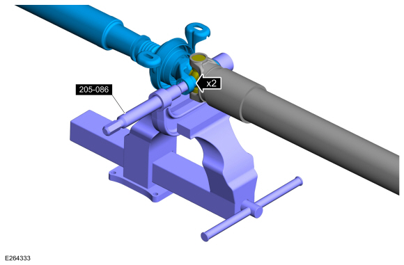
Using the special tool, press the U-joint bearing cups out of the driveshaft yoke and remove the driveshaft yoke.
Use Special Service Tool: 205-086 (T74P-4635-C) Installer/Remover, C-Frame and Screw.
Use the General Equipment: Vise
 |
-
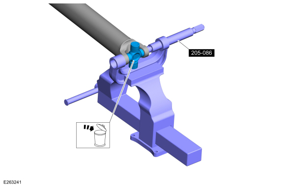
Using the special tool, press the U-joint bearing cups out of the driveshaft yoke and remove the U-joint.
Use Special Service Tool: 205-086 (T74P-4635-C) Installer/Remover, C-Frame and Screw.
Use the General Equipment: Vise
 |
-
NOTE: Inspect the bearing cup bores and retaining ring grooves. Remove any rust or other surface irregularities.
NOTE: Center bearing U-joint shown, others similar.
Clean and inspect the U-joint bearing cup surfaces.
 |
ASSEMBLY
NOTE: Install the U-joint kits as complete assemblies only. Do not mix components from other U-joint kits.
-
Lube the U-joint bearing cup bores.
Material: Motorcraft® Premium Long-Life Grease / XG-1-E1 (ESA-M1C75-B)
 |
-
NOTE: The tripod bearing cup needle bearings need to be in the correct position.
Using the special tool, install the new U-joint spider and bearing cups into the driveshaft yoke.
Use Special Service Tool: 205-086 (T74P-4635-C) Installer/Remover, C-Frame and Screw.
Use the General Equipment: Vise
 |
-
Install the new bearing cup snap rings into the driveshaft yoke grooves.
 |
-
NOTE: Driveshaft to rear axle flange yoke U-joint shown, others similar.
Using the special tool, install the new bearing cups on the opposite side of the driveshaft slip yoke.
Use Special Service Tool: 205-086 (T74P-4635-C) Installer/Remover, C-Frame and Screw.
Use the General Equipment: Vise
 |
-
Install the new bearing cup snap rings into the driveshaft yoke grooves.
 |
-
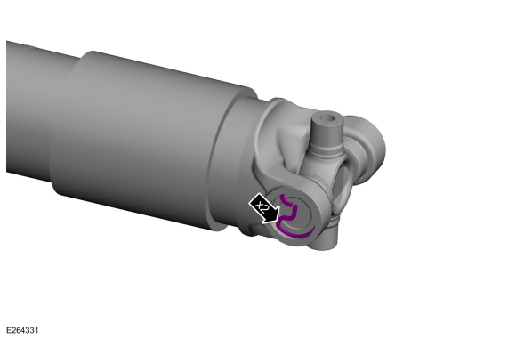
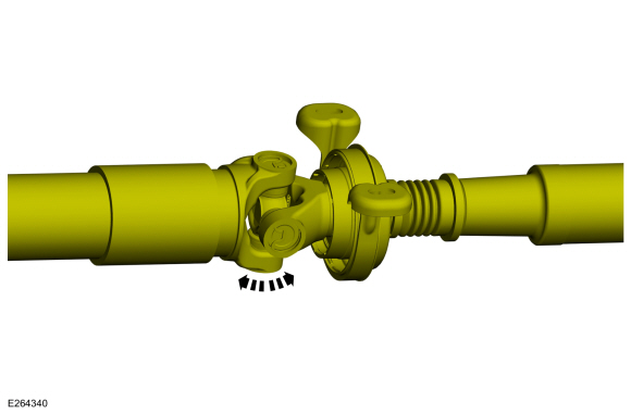
Rotate the driveshaft yoke to make sure the U-joints are
free to rotate easily, without binding, before installing the
driveshaft.
 |
-
Install the driveshaft.
Refer to: Rear Driveshaft (205-01 Driveshaft, Removal and Installation).
 Rear Driveshaft. Removal and Installation
Special Tool(s) /
General Equipment
Flat Headed Screw Driver
Tire Lever
Removal
All vehicles
With the vehicle in NEUTRAL, position it on a hoist...

Other information:
Lincoln Navigator 2018-2026 Workshop Manual: Satellite Radio Antenna. Removal and Installation
Removal Lower the headliner. Refer to: Headliner - Lowering (501-05 Interior Trim and Ornamentation, Removal and Installation). Disconnect the electrical connector. Separate the wiring harness guide. Remove the satellite radio antenna bolt. Torque: 62 lb.in (7 Nm) Remove the satellite radio antenna retai..
Lincoln Navigator 2018-2026 Workshop Manual: 360 Degree View Camera Alignment. General Procedures
NOTE: On vehicles equipped with Trailer Reverse Guidance (TRG) complete this procedure and also perform the Trailer Reverse Guidance camera alignment. NOTE: Damage to or misalignment of any of the cameras or the body panels they are mounted to can cause the camera alignment to be unsuccessful. Prior to beginning this procedure, perform the following: Verify..
Categories
- Manuals Home
- 4th Gen Lincoln Navigator Service Manual (2018 - 2026)
- Neutral Flat Tow Activation and Deactivation. General Procedures
- Identification Codes. Description and Operation
- Front Seat. Removal and Installation
- Front Bumper Cover. Removal and Installation
- Windshield Washer Pump. Removal and Installation
Rear Stabilizer Bar Link. Removal and Installation
Removal
NOTE: Removal steps in this procedure may contain installation details.
With the vehicle in NEUTRAL, position it on a hoist.Refer to: Jacking and Lifting (100-02 Jacking and Lifting, Description and Operation).
NOTE: Use the hex-holding feature to prevent the stud from turning while removing the nut.
Remove and discard the 2 rear stabilizer bar link nuts and remove the rear stabilizer bar link.Torque: 46 lb.ft (63 Nm)
