Lincoln Navigator: Suspension System - General Information / Front Camber and Caster Adjustment. General Procedures
Special Tool(s) / General Equipment
| Vehicle/Axle Stands |
Adjustment
NOTICE: Suspension fasteners are critical parts that affect the performance of vital components and systems. Failure of these fasteners may result in major service expense. Use the same or equivalent parts if replacement is necessary. Do not use a replacement part of lesser quality or substitute design. Tighten fasteners as specified.
NOTICE: Do not remove the stabilizer bar brackets until the stabilizer links have been disconnected or damage to the stabilizer bar links may occur.
NOTE: To allow for adjustment of the lower arm in the frame slots, the lower arm bolts and nuts must be removed and discarded. They are replaced with cam bolt kit 3C333. The vehicle should be supported by the frame to ease movement of the lower arm in the slot.
-
Using alignment equipment and the manufacturers instructions, measure the front caster and camber.
-
For optimal alignment settings,
Refer to: Specifications (204-00 Suspension System - General Information, Specifications).
-
If the caster and camber values are not within specification, go to the next step.
-
For optimal alignment settings,
-
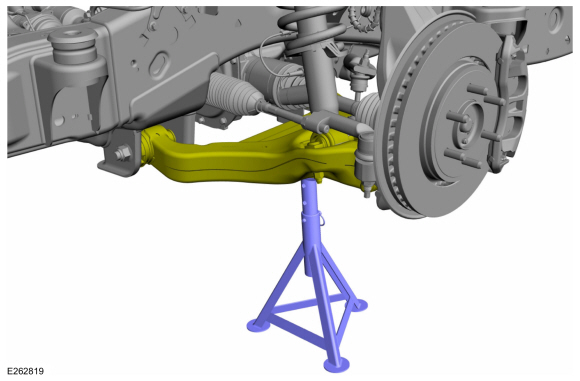
Support the lower arm.
Use the General Equipment: Vehicle/Axle Stands
 |
-
NOTE: Support the lower arm with a jackstand.
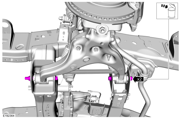
On both sides.
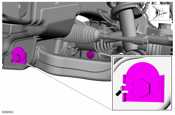
Remove and discard the 2 lower arm nuts and bolts.
Use the General Equipment: Vehicle/Axle Stands
 |
-
NOTE: Use the hex-holding feature to prevent the stud from turning while removing the nuts.
On both sides.
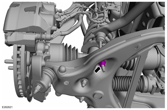
Remove and discard the stabilizer bar link lower nuts.
 |
-
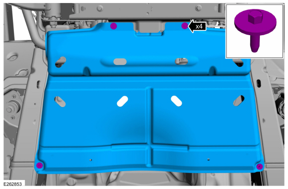
NOTE: If equipped.
Remove the underbody shield retainers and the underbody shield.
 |
-
-
On both sides.
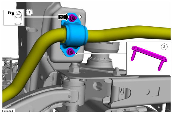
Remove and discard the front stabilizer bar bracket nuts.
-
On both sides.
Remove the front stabilizer bar bracket retainer.
-
Position the front stabilizer bar aside.
-
On both sides.
 |
-
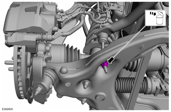
NOTE: The new cam bolts must be installed opposite of the original lower arm bolt orientation.
NOTE: Only tighten the nuts and bolts finger tight at this stage.
NOTE: Make sure that the locating tab in inserted into the hole in the frame.
On both sides.
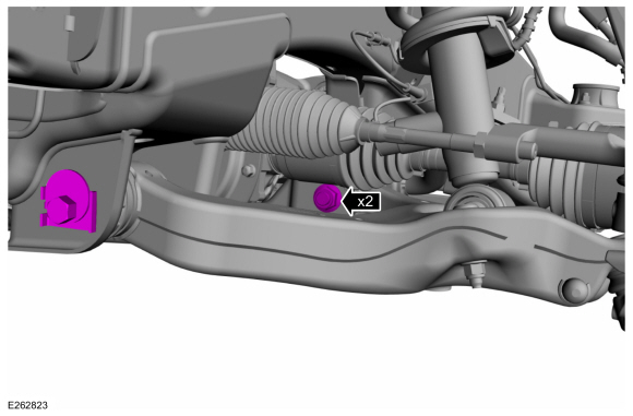
Install the 2 new cam bolt kits.
 |
-
To adjust the caster and camber, refer to the following chart.
-
Adjustments that require moving the front and the rear of the lower arm should be made equally.
Adjustment Front of Lower Arm Rear of Lower Arm Increase caster In Out Decrease caster Out In Increase camber In In Decrease camber Out Out Increase caster and camber simultaneously In — Decrease caster and camber simultaneously Out —
-
Adjustments that require moving the front and the rear of the lower arm should be made equally.
-
On both sides.
With the weight of the vehicle resting on the wheel and tire assemblies, hold the cam bolts and tighten the nuts.
Torque: 258 lb.ft (350 Nm)
 |
-
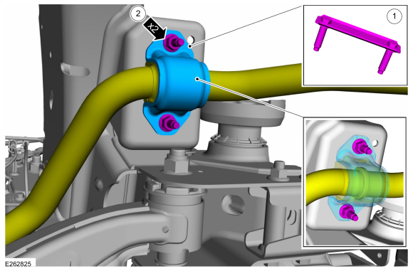
NOTICE: The raised ring on the stabilizer bar must be encapsulated inside the inner groove of the stabilizer bar bushing on the driver side of the vehicle for proper installation.
-
On both sides.
Install front stabilizer bar bracket retainer.
-
On both sides.
Position the stabilizer bar and install the new front stabilizer bar bracket nuts.
Torque: 46 lb.ft (63 Nm)
-
On both sides.
 |
-
NOTE: If equipped.
Install the underbody shield and the underbody shield retainers.
Torque: 71 lb.in (8 Nm)
|
-
NOTE: Use the hex-holding feature to prevent the stud from turning while removing the nuts.
On both sides.
Install the new stabilizer bar link lower nuts.
Torque: 59 lb.ft (80 Nm)
 |
-
Check and if necessary, adjust front toe.
Refer to: Front Toe Adjustment (204-00 Suspension System - General Information, General Procedures).
 Suspension System. Diagnosis and Testing
Preliminary Inspection
Road test the vehicle.
If any suspension alignment or ride height concerns are present, REFER to Symptom Chart: Suspension System...
 Front Toe Adjustment. General Procedures
Special Tool(s) /
General Equipment
Wheel Alignment System
Adjustment
NOTE:
Make sure that the vehicle is standing on a level surface...
Other information:
Lincoln Navigator 2018-2026 Workshop Manual: Wipers and Washers - Overview. Description and Operation
Overview The windshield wiper/washer system is activated by the wiper/washer switch. The following functions/ features of the windshield wiper/washer system are: Mist wipe Windshield wash (includes front camera wash, if equipped) Courtesy wipe Windshield wipers (low/high speed) Intermittent wipers Speed dependent wipers Wiper activate..
Lincoln Navigator 2018-2026 Workshop Manual: Gateway Module A (GWM). Removal and Installation
Removal NOTE: Removal steps in this procedure may contain installation details. NOTE: If installing a new module, it is necessary to upload the module configuration information to the scan tool prior to removing the module. This information must be downloaded into the new module after installation. Using a diagnostic scan tool, begin the PMI process for the GWM fol..
Categories
- Manuals Home
- 4th Gen Lincoln Navigator Service Manual (2018 - 2026)
- Neutral Flat Tow Activation and Deactivation. General Procedures
- Front Bumper Cover. Removal and Installation
- Body and Paint
- Brake Service Mode Activation and Deactivation. General Procedures
- Transmission Fluid Level Check. General Procedures
Rear Camber Adjustment. General Procedures
Special Tool(s) / General Equipment
Wheel Alignment SystemActivation
NOTICE: Suspension fasteners are critical parts that affect the performance of vital components and systems. Failure of these fasteners may result in major service expense. Use the same or equivalent parts if replacement is necessary. Do not use a replacement part of lesser quality or substitute design. Tighten fasteners as specified.
Using alignment equipment and the manufacturer's instructions, measure the rear camber.Use the General Equipment: Wheel Alignment System