Lincoln Navigator: Driveshaft / Driveshaft Runout and Balancing. General Procedures
Special Tool(s) / General Equipment
 |
100-002
(TOOL-4201-C)
Holding Fixture with Dial Indicator Gauge |
Inspection
NOTE: Driveline vibration exhibits a higher frequency and lower amplitude then high-speed shake. Driveline vibration is directly related to the speed of the vehicle and is noticed at various speeds. Driveline vibration can be perceived as a tremor in the floorpan or heard as a rumble, hum or boom.
NOTE: Refer to Specifications in this section for runout specifications.
-
NOTE: Do not make any adjustments before carrying out a road test. Do not change the tire pressure or the vehicle load.
- Carry out a visual inspection of the vehicle. Operate the vehicle and verify the condition by reproducing it during the road test.
-
The concern should be directly related to vehicle
road speed. not affected by acceleration or deceleration or could be
reduced by coasting in NEUTRAL.
-
Raise and support the vehicle.
Refer to: Jacking and Lifting (100-02 Jacking and Lifting, Description and Operation).
-
NOTE: The driveshaft should be kept at an angle equal to or close to the curb-weighted position. Use a twin-post hoist or a frame hoist with jackstands.
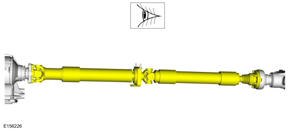
- Inspect the driveshaft for damage, undercoating or incorrectly seated U-joints. Rotate the driveshaft slowly by hand and feel for binding or end play in the U-joint trunions. Remove the driveshaft. Inspect the slip yoke splines for any galling, dirt, rust or incorrect lubrication. Clean the driveshaft or install new U-joints as necessary. Install a new driveshaft if damaged. After any corrections or new components are installed, recheck for the vibration at the road test speed.
- If the vibration persists after inspection, measure the driveshaft runout.
 |
Check
-
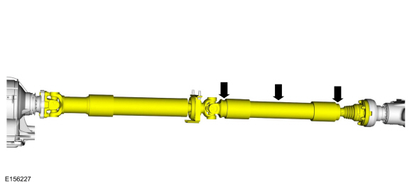
NOTE:
- Measure and check for the specified maximum value. Install the Dial Indicator Gauge with Holding Fixture. Rotate the driveshaft by turning the axle and measure the runout at the front, center and rear of the driveshaft. Multiple piece driveshaft measure each section at the front, center and rear.
-
If the runout exceeds the maximun specification at the front or center, install a new driveshaft.
Refer to: Specifications (205-01 Driveshaft, Specifications).
Use Special Service Tool: 100-002 (TOOL-4201-C) Holding Fixture with Dial Indicator Gauge.
-
If the front and center is within the maximun
specification , but the rear runout is not, index-mark the rear runout
high point and proceed to step 2.
Refer to: Specifications (205-01 Driveshaft, Specifications).
-
If the runout is within the maximun specification at
all points, recheck for vibration at road test speed. If the vibration
persists, balance the driveshaft. Refer to Driveshaft Balancing in this
procedure.
Refer to: Specifications (205-01 Driveshaft, Specifications).
 |
-
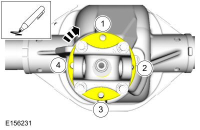
NOTE: Circular pinion flanges can be turned in 90 degree or one-fourth increments. Half-round pinion flanges are limited to 2 positions. CV joint pinion flanges that have 6 bolts, can be turned in 60 degree or one-sixth increments.
- Index-mark the driveshaft to the pinion flange. Disconnect the driveshaft and rotate it 180 degrees. Reconnect the driveshaft. Recheck the runout at the rear of the driveshaft.
-
If the runout is still over specification, mark the high point and proceed to Step 3.
-
If the runout is within specification, check for the
vibration at the road test speed. If the vibration is still present,
balance the driveshaft. Refer to Driveshaft Balancing in this procedure.
-
NOTE:
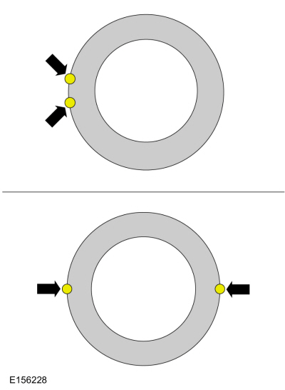
- Excessive driveshaft runout can originate in the driveshaft itself or from the pinion flange. To find the source, compare the 2 high points previously determined.
-
If the index marks are close together, within 25 mm
(1 in), the driveshaft is eccentric. Install a new driveshaft.
-
If the marks are on opposite sides of the
driveshaft, 180 degrees apart, the slip yoke or pinion flange is
responsible. Check the pinion flange runout. If the pinion flange runout
exceeds specifications, a bent pinion is indicated.
Refer to: Rear Drive Axle and Differential (205-02 Rear Drive Axle/Differential - Vehicles With: Ford 9.75 Inch Ring Gear, Diagnosis and Testing).
Refer to: Rear Drive Axle and Differential - Vehicles With: Electronic Limited-Slip Differential (205-02 Rear Drive Axle/Differential - Vehicles With: Ford 9.75 Inch Ring Gear, Diagnosis and Testing).
-
If the pinion flange and pinion runouts are within
specifications, road test and check for the vibration at the road test
speed. If the vibration persists, balance the driveshaft. Refer to
Driveshaft Balancing in this procedure.
 |
Driveshaft Balancing-Using the VCMM (Vehicle Communication and Measurement Module) and VMS (Vehicle Measurement System)
-
Special Tool(s): VCMM and VMS
. Working under the vehicle, install an accelerometer. The
accelerometer can be attached and mounted near either the transmission
or differential end of the driveshaft.
-
NOTE:
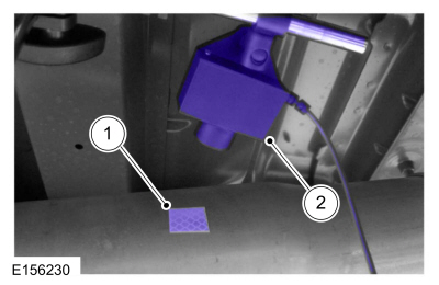
- Clean an area of the driveshaft and install the reflective tape, then install the photo-tachometer sensor. The sensor should be placed at approximately a 20-degree angle from perpendicular to the surface of the reflective tape. Make sure the sensor does not get moved during the balance procedure.
-
Reflective tape.
-
Photo-tachometer sensor.
 |
-
Special Tool(s): VCMM and VMS . Run a driveshaft balance test with the driveshaft unmodified.
Use Special Service Tool: 100-002 (TOOL-4201-C) Holding Fixture with Dial Indicator Gauge.
Vehicles with tapped pinion flanges
-
Label the tapped holes in the pinion flange
numerically, starting at the top hole as 1. Mark the remaining holes 2,
3, 4, (depending on flange type, 5 and 6 may also be needed). Label in
the direction of rotation.
 |
-
Special Tool(s): VCMM and VMS . Run a second test with the 12 mm (0.47
in) test weight set screw in the No. 1 hole, previously marked on the
pinion flange.
-
Remove the test weight, then install the weight combination directed by the VCMM and VMS .
Vehicles without tapped pinion flanges
-
NOTE:
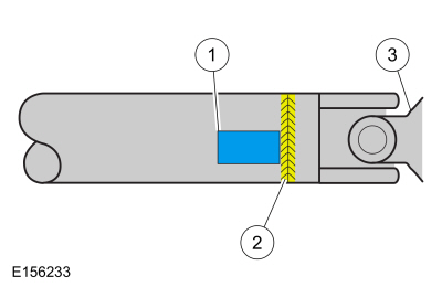
- Special Tool(s): VCMM and VMS . Run a second test with a test weight. Using a metal band, secure the test weight to the end of the driveshaft. The weight should be placed at the end of the driveshaft tube, as close to the tube-to-yoke weld seam as possible. Mark the location of the test weight on the driveshaft, as shown in the figure below.
-
Test weight.
-
Tube-to-yoke weld seam.
-
Driveshaft pinion flange.
-
Select the test weight based on driveshaft size.
Larger driveshafts use 10 g (0.353 oz). Smaller driveshafts use 5 g
(0.176 oz).
 |
-
NOTE:
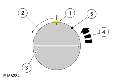
- Remove the test weight, then install the recommended weight at the position directed by the VCMM and VMS . Using a metal band and epoxy, secure the test weight to the driveshaft, as shown in the figure below.
-
Test weight.
-
Measure in this direction.
-
Driveshaft diameter.
-
Directional rotation.
-
Balance weight relative to test weight centerline.
-
The results are displayed with respect to the location to where the test weight was placed.
 |
All vehicles
-
Special Tool(s): VCMM and VMS . Run a third test to verify the repair.
Driveshaft Balancing – Hose Clamp Method
-
Install 1 or 2 hose clamps on the driveshaft, near
the rear. Position of the hose clamp head(s) can be determined through
trial and error.
-
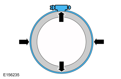
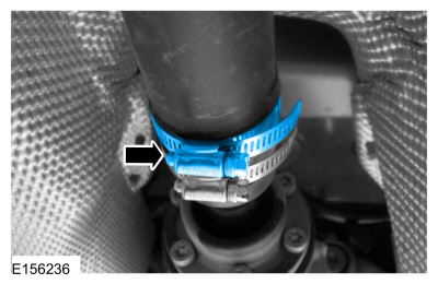
Mark the rear of the driveshaft into 4 approximately
equal sectors and number the marks 1 through 4. Install a hose clamp on
the driveshaft with its head at position No. 1, as shown in the figure
below. Check for vibration at road speed. Recheck with the clamp at each
of the other positions to find the position that shows minimum
vibration. If 2 adjacent positions show equal improvement, position the
clamp head between them.
 |
-
If the vibration persists, add a second clamp at the same position and recheck for vibration.
 |
-
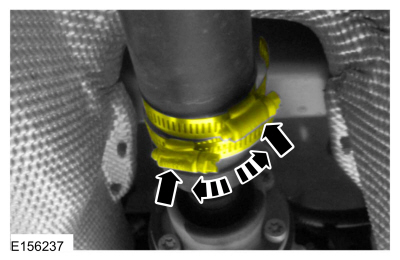
If no improvement is noted, rotate the clamps in
opposite directions, equal distances from the best position determined
in Step 14. Separate the clamp heads about 13 mm (1/2 in) and recheck
for vibration at the road speed.
 |
-
Repeat the process with increasing separation until
the best combination is found or the vibration is reduced to an
acceptable level.
 Driveshaft Angle Measurement. General Procedures
Check
NOTE:
This procedure does not apply to CV joints, flex couplers or
double cardan joints that are used in some driveshafts. This check is
for single-cross and roller-style joints found in the driveshafts...
 Front Driveshaft. Removal and Installation
Special Tool(s) /
General Equipment
Crimping Tool
Materials
Name
Specification
Motorcraft® Premium Long-Life GreaseXG-1-E1
ESA-M1C75-B
Removal
With the vehicle in NEUTRAL, position the vehicle on a hoist...
Other information:
Lincoln Navigator 2018-2026 Workshop Manual: Variable Camshaft Timing (VCT) Unit. Removal and Installation
Removal NOTICE: During engine repair procedures, cleanliness is extremely important. Any foreign material, including any material created while cleaning gasket surfaces, that enters the oil passages, coolant passages or the oil pan, can cause engine failure...
Lincoln Navigator 2018-2026 Workshop Manual: Ethernet Module Communications Network - System Operation and Component Description. Description and Operation
System Operation System Diagram NOTE: The system diagrams include all component options. Some components may not be equipped on the vehicle. Ethernet Communication Network *.sttxt { visibility: hidden; } *.stcallout { visibility: visible; } E369249 ..
Categories
- Manuals Home
- 4th Gen Lincoln Navigator Service Manual (2018 - 2026)
- Transmission Fluid Level Check. General Procedures
- Head Up Display (HUD) Module Calibration. General Procedures
- Front Bumper Cover. Removal and Installation
- Identification Codes. Description and Operation
- Brake Service Mode Activation and Deactivation. General Procedures
Rear Drive Axle and Differential. Diagnosis and Testing
Symptom Chart(s)
Diagnostics in this manual assume a certain skill level and knowledge of Ford-specific diagnostic practices.
REFER to: Diagnostic Methods (100-00 General Information, Description and Operation).
Symptom Chart - Differential
Symptom Chart - Differential
Condition Actions Axle overheating GO to Pinpoint Test A Broken gear teeth on the ring gear or pinion GO to Pi