Lincoln Navigator: Driveshaft / Driveshaft Angle Measurement. General Procedures
Check
NOTE: This procedure does not apply to CV joints, flex couplers or double cardan joints that are used in some driveshafts. This check is for single-cross and roller-style joints found in the driveshafts.
NOTE: Prior to checking driveline angularity, inspect the U-joints for correct operation.
NOTE: An incorrect driveline angle can cause a vibration or shudder.
NOTE: Driveline angularity is the angular relationship between the engine crankshaft, the driveshaft and the rear axle pinion. Factors determining driveline angularity include ride height, rear spring and engine mounts.
-
NOTE:
- Special Tool(s): Anglemaster II Driveline Inclinometer/Protractor 164-R2402. Carry out the following preliminary setup steps:
-
Inspect the U-joints for correct operation.
-
Park the vehicle on a level surface such as a drive-on hoist, or back onto a front end alignment rack.
-
Verify the curb position ride height is within
specifications with the vehicle unloaded and all of the tires are
inflated to their normal operating pressures.
-
Calibrate the Anglemaster II Driveline
Inclinometer/Protractor by placing it on a clean, flat level section of
the frame rail and press the ALT-ZERO button.
Vehicles with flat-flanged, split-pin or slip-flanged U-joints
-
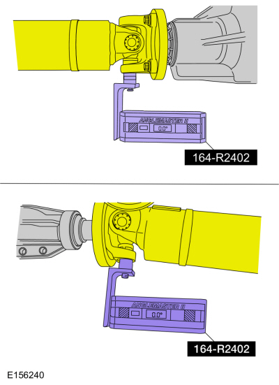
NOTE: If equipped, remove the snap ring to allow access to the base of the U-joint cup. Make sure the Anglemaster II Driveline Inclinometer/Protractor is seated against the U-joint cup.
NOTE: Rotate the driveshaft until the flange U-joint cup is parallel with the floor. This will simplify taking measurements.
Special Tool(s): Anglemaster II Driveline Inclinometer/Protractor 164-R2402. Check and record the flange angle as angle A.
 |
-
Special Tool(s): Anglemaster II Driveline
Inclinometer/Protractor 164-R2402. Measure the slope of the connecting
component. Record the measurement of the component angle as angle B.
 |
Multiple piece driveshafts
-
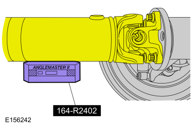
NOTE: Repeat this step for each center support bearing on the driveshaft.
NOTE: It is not necessary to remove the U-joint snap ring, if equipped, for these measurements.
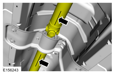
Special Tool(s): Anglemaster II Driveline Inclinometer/Protractor 164-R2402. Measure the slope of the components in front and behind the center support bearing U-joint in the area indicated. Record the front component as angle A, and the rear component as angle B.
 |
All vehicles
-
NOTE: When 2 connected components slope in the same direction, subtract the smallest number from the larger number to find the U-joint operating angle. When 2 connected components slope in the opposite direction, add the measurements to find the U-joint operating angle.
Calculate the difference in the slope of the components to determine the U-joint operating angle.
-
The U-joint operating angle is the angle formed by 2
yokes connected by a cross and bearing kit. Ideally, the operating
angles on each connection of the driveshaft should be equal or within
1.5 degree of each other.
-
If the angle is not within specifications, repair or
adjust to obtain the correct angle. Inspect the engine mounts,
transmission mounts, center support bearing mounting, rear suspension,
rear axle, rear axle mounting or the frame for wear or damage.
 Driveshaft. Diagnosis and Testing
Symptom Chart(s)
Diagnostics in this manual assume a certain skill level and knowledge of Ford-specific diagnostic practices.REFER to: Diagnostic Methods (100-00 General Information, Description and Operation)...
 Driveshaft Runout and Balancing. General Procedures
Special Tool(s) /
General Equipment
100-002
(TOOL-4201-C)
Holding Fixture with Dial Indicator Gauge
Inspection
NOTE:
Driveline vibration exhibits a higher frequency and lower
amplitude then high-speed shake...
Other information:
Lincoln Navigator 2018-2026 Workshop Manual: Tie Rod. Removal and Installation
Special Tool(s) / General Equipment Boot Clamp Pliers Materials Name Specification Motorcraft® Premium Long-Life GreaseXG-1-E1 ESA-M1C75-B Removal Remove the tie rod end. Refer to: Tie Rod End (211-02 Power Steering, Removal and Installation)...
Lincoln Navigator 2018-2026 Workshop Manual: Drive Pinion Seal. Removal and Installation
Special Tool(s) / General Equipment 205-208 (T83T-4676-A) Installer, Drive Pinion Oil SealTKIT-1983-FTKIT-1983-FLMTKIT-1983-FX Flat-Bladed Screwdriver Materials Name Specification Motorcraft® Premium Long-Life GreaseXG-1-E1 ESA-M1C75-B Removal Remove the drive pinion flange...
Categories
- Manuals Home
- 4th Gen Lincoln Navigator Service Manual (2018 - 2026)
- Rear Bumper. Removal and Installation
- Transmission Fluid Drain and Refill. General Procedures
- Front Seat. Removal and Installation
- Vehicle Dynamics Control Module (VDM). Removal and Installation
- All Terrain Control Module (ATCM). Removal and Installation
Front Stabilizer Bar Link. Removal and Installation
Removal
NOTICE: Suspension fasteners are critical parts that affect the performance of vital components and systems. Failure of these fasteners may result in major service expense. Use the same or equivalent parts if replacement is necessary. Do not use a replacement part of lesser quality or substitute design. Tighten fasteners as specified.
NOTE: Removal steps in this procedure may contain installation details.
With the vehicle in NEUTRAL, position it on a hoist.Refer to: Jacking and Lifting (100-02 Jacking and Lifting, Description and Operation).
NOTICE: Do not use power tools to remove or install the stabilizer bar