Lincoln Navigator: Fuel Charging and Controls - Turbocharger - 3.5L EcoBoost (272kW/370PS) / Turbocharger Oil Return Tube LH. Removal and Installation
Materials
| Name | Specification |
|---|---|
| Motorcraft® Metal Brake Parts Cleaner PM-4-A, PM-4-B, APM-4-C |
- |
Removal
NOTICE: The turbocharger compressor vanes can be damaged by even the smallest particles. When removing any turbocharger or engine air intake system component, ensure that no debris enters the system. Failure to do so may result in damage to the turbocharger.
NOTICE: Special attention needs to be given to the sealing ports for the oil feed, the oil drain, and the coolant lines, on turbocharged engines. The sealing ports must be totally clean and free from O-ring residue, have no damage to the sealing surface and the lines to ensure that there are no leaks or repeat repairs.
-
Remove the turbocharger oil supply tube LH.
Refer to: Turbocharger Oil Supply Tube LH (303-04B Fuel Charging and Controls - Turbocharger - 3.5L EcoBoost (272kW/370PS), Removal and Installation).
-
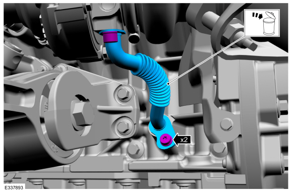
Remove the turbocharger oil return tube bolts, then remove and discard the turbocharger oil return tube.
 |
Installation
-
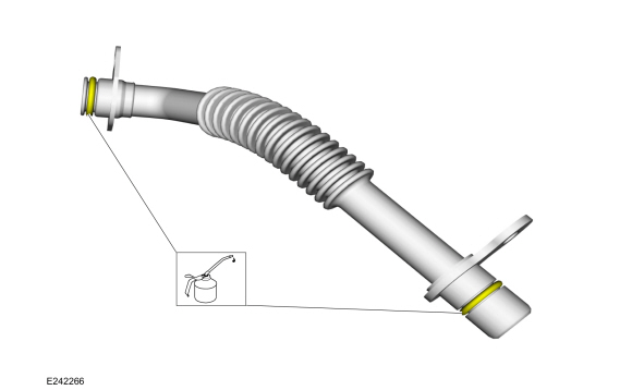
Lubricate the new turbocharger oil return tube O-ring seals with clean engine oil.
Refer to: Specifications (303-01 Engine - 3.5L V6 PowerBoost (CN)) .
 |
-
-
NOTICE: Do not use a metal brush, damage to the sealing area will result in leaks.
Carefully use a nylon brush to remove the old O-ring residue, use brake cleaner to rinse the O-ring residue out of the turbocharger and engine O-ring bores. Inspect the area for deep scratches and gouges. Install new components if necessary.
-
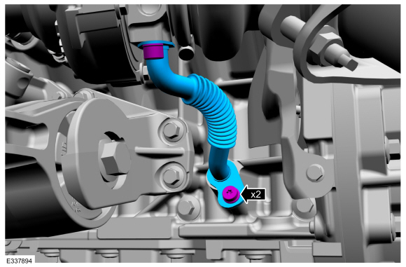
Fully seat the turbocharger oil return tube into the
turbocharger and engine bore holes flush to 2.5 mm off of the mounting
surface prior to tightening the bolts. Install the new turbocharger oil
return tube, then install and tighten the turbocharger oil return tube
bolts.
Material: Motorcraft® Metal Brake Parts Cleaner / PM-4-A, PM-4-B, APM-4-C
Torque:
Stage 1: Tighten to : 89 lb.in (10 Nm)
Stage 2: Tighten an additional : 30°
-
 |
-
Install the turbocharger oil supply tube LH.
Refer to: Turbocharger Oil Supply Tube LH (303-04B Fuel Charging and Controls - Turbocharger - 3.5L EcoBoost (272kW/370PS), Removal and Installation).
 Turbocharger LH. Removal and Installation
Materials
Name
Specification
Motorcraft® High Temperature Nickel Anti-Seize LubricantXL-2
-
Motorcraft® Metal Brake Parts CleanerPM-4-A, PM-4-B, APM-4-C
-
Removal
NOTICE:
The turbocharger compressor vanes can be damaged by even the
smallest particles...
 Turbocharger Oil Return Tube RH. Removal and Installation
Materials
Name
Specification
Motorcraft® Metal Brake Parts CleanerPM-4-A, PM-4-B, APM-4-C
-
Removal
NOTICE:
The turbocharger compressor vanes can be damaged by even the
smallest particles...
Other information:
Lincoln Navigator 2018-2026 Workshop Manual: Third Row Center Seatbelt Retractor - Short Wheelbase. Removal and Installation
Special Tool(s) / General Equipment Flat-Bladed Screwdriver Removal NOTE: Removal steps in this procedure may contain installation details. Disconnect the third row center seatbelt from the third row center seatbelt buckle assembly...
Lincoln Navigator 2018-2026 Workshop Manual: Fuel Rail Pressure and Temperature Sensor. Removal and Installation
Removal Release the fuel system pressure. Refer to: Fuel System Pressure Release (310-00 Fuel System - General Information - 3.5L EcoBoost (272kW/370PS), General Procedures). Remove the intake manifold. Refer to: Intake Manifold (303-01 Engine - 3...
Categories
- Manuals Home
- 4th Gen Lincoln Navigator Service Manual (2018 - 2026)
- Front Seat. Removal and Installation
- Neutral Flat Tow Activation and Deactivation. General Procedures
- Transmission Fluid Level Check. General Procedures
- Telematics Control Unit (TCU) Module. Removal and Installation
- Rear Bumper. Removal and Installation
Diagnostic Methods. Description and Operation
This document provides critical diagnostic knowledge required for successful repair outcomes. It identifies technical competencies expected by users of this manual.
Ford Diagnostic Assumptions
Ford diagnostics assume the vehicle concern described by the test title is currently present. Exceptions to this rule are noted in each test. Do not replace modules or other components as directed by a diagnostic if the concern is not present at the time of testing.