Lincoln Navigator: Fuel Charging and Controls - Turbocharger - 3.5L EcoBoost (272kW/370PS) / Turbocharger LH. Removal and Installation
Materials
| Name |
Specification |
Motorcraft® High Temperature Nickel Anti-Seize Lubricant
XL-2 |
-
|
Motorcraft® Metal Brake Parts Cleaner
PM-4-A, PM-4-B, APM-4-C |
-
|
Removal
NOTICE:
The turbocharger compressor vanes can be damaged by even the
smallest particles. When removing any turbocharger or engine air intake
system component, ensure that no debris enters the system. Failure to
do so may result in damage to the turbocharger.
NOTICE:
Special attention needs to be given to the sealing ports for
the oil feed, the oil drain, and the coolant tubes, on turbocharged
engines. The sealing ports must be totally clean and free from O-ring
residue, have no damage to the sealing surface and the tubes to ensure
that there are no leaks or repeat repairs.
-
Drain the cooling system.
Refer to: Engine Cooling System Draining, Vacuum Filling and Bleeding
(303-03 Engine Cooling - 3.5L EcoBoost (272kW/370PS), General
Procedures).
-
Remove the engine rear undershield.
-
Remove the left front fender splash shield.
Refer to: Fender Splash Shield (501-02 Front End Body Panels, Removal and Installation).
-
Remove the charge air cooler intake pipe - left side.
Refer to: Charge Air Cooler (CAC) Intake Pipe (303-12 Intake Air
Distribution and Filtering - 3.5L EcoBoost (272kW/370PS), Removal and
Installation).
-
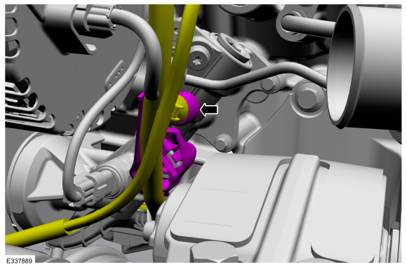
Detach the harness retainer, then move the harness out of the way.
-
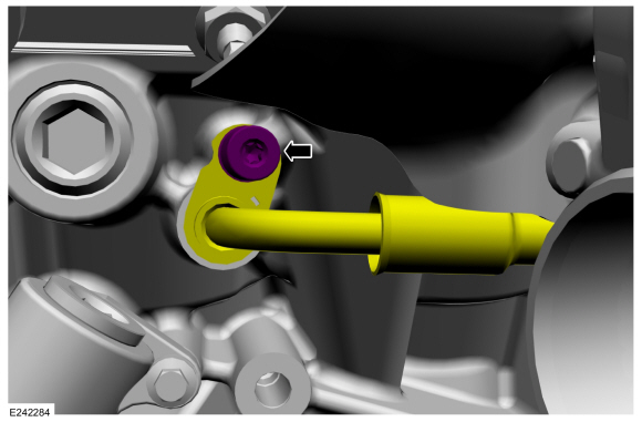
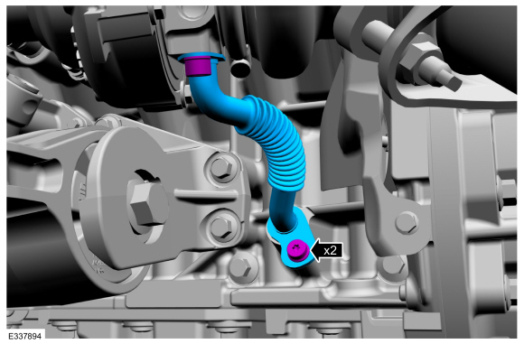
NOTE:
The left turbocharger oil supply tube does not have a turbocharger oil supply filter.
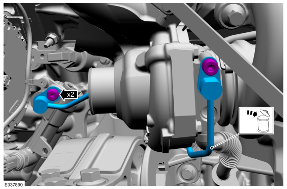
Remove the turbocharger oil supply tube bolts, then remove and discard the turbocharger oil supply tube.
-
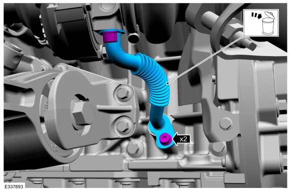
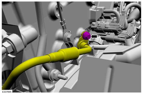
Remove the turbocharger oil return tube bolts, then remove and discard the turbocharger oil return tube.
-
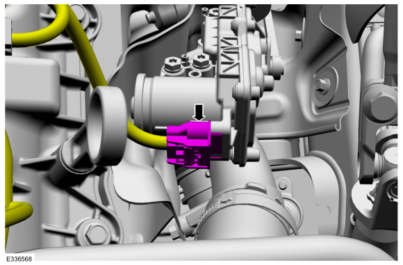
Disconnect the wastegate control actuator electrical connector.
-
Remove the catalytic converter LH.
Refer to: Catalytic Converter LH (309-00 Exhaust System - 3.5L EcoBoost (272kW/370PS), Removal and Installation).
-
NOTICE:
If the 2 piece turbocharger cooling tubes are
separated or the rubber gasket is leaking, then the rubber gasket must
be replaced.
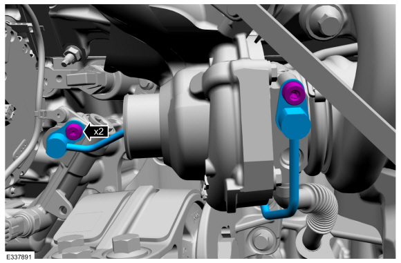
Remove the turbocharger coolant supply tube bolt, then
disconnect the turbocharger coolant supply tube from the engine.
-
NOTICE:
If the 2 piece turbocharger cooling tubes are
separated or the rubber gasket is leaking, then the rubber gasket must
be replaced.
Remove the turbocharger coolant return tube bolt, then
disconnect the turbocharger coolant return tube from the engine.
-
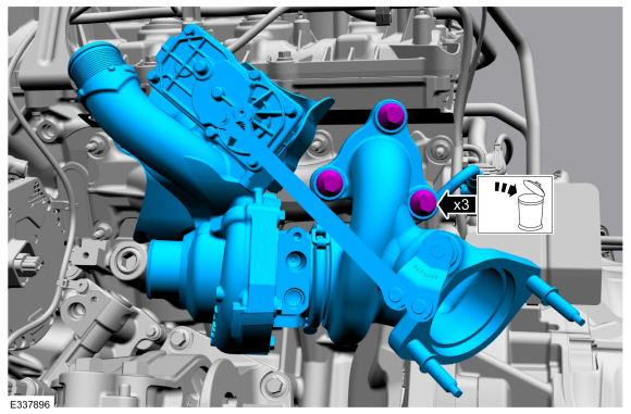
NOTE:
Remove the coolant tubes with the turbocharger. If
the 2 piece turbocharger cooling tubes are separated, then the rubber
gasket must be replaced.
Remove and discard the turbocharger retainers, then remove the turbocharger.
-
-
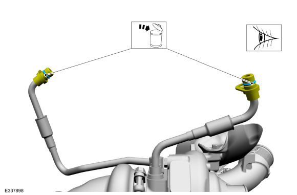
Remove and discard the turbocharger coolant tube O-ring seals.
-
NOTICE:
Do not use a metal brush, damage to sealing area will result in leaks.
Use brake cleaner and a nylon brush to clean. Clean
the turbocharger coolant tube sealing surfaces. Inspect the sealing
surfaces for debris or damage and make sure the retaining bracket is not
bent, check for squareness of the O-ring area. Install new components
if necessary.
-
NOTICE:
If the 2 piece turbocharger cooling tubes were
separated or the rubber gasket is leaking, then the rubber gasket must
be replaced.
If needed, then remove and discard the rubber gasket.
-
NOTICE:
Do not use a metal brush, damage to sealing area will result in leaks.
If needed, inspect and clean the turbocharger cooling
tube sealing surfaces, using brake cleaner and a nylon brush to clean.
Install new components if necessary.
Material: Motorcraft® Metal Brake Parts Cleaner
/ PM-4-A, PM-4-B, APM-4-C
-
If needed, remove the turbocharger coolant tubes from the turbocharger.
Refer to: Turbocharger Coolant Return Tube LH (303-04B Fuel Charging
and Controls - Turbocharger - 3.5L EcoBoost (272kW/370PS), Removal and
Installation).
Refer to: Turbocharger Coolant Supply Tube LH (303-04B Fuel Charging
and Controls - Turbocharger - 3.5L EcoBoost (272kW/370PS), Removal and
Installation).
-
Remove and discard the turbocharger gasket.
-
If needed, remove the studbolts.
Installation
-
Make sure that the mating faces are clean and free of foreign material.
-
If removed, apply high temperature nickel anti-seize
lubricant to the studbolt threads, then install and tighten the
studbolts.
Material: Motorcraft® High Temperature Nickel Anti-Seize Lubricant
/ XL-2
Torque:
30 lb.ft (40 Nm)
-
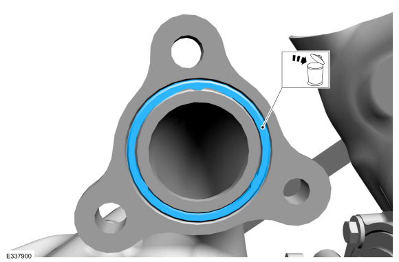
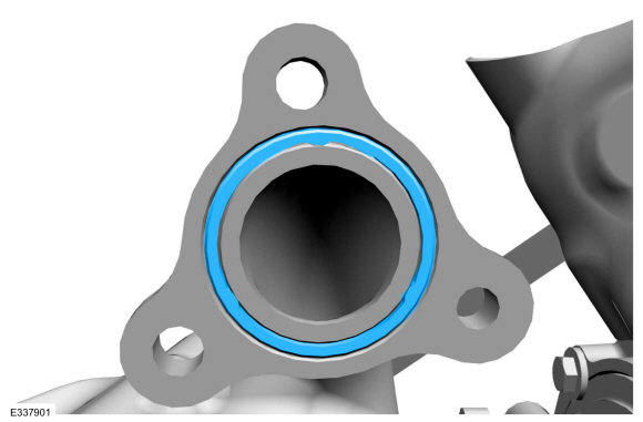
Install the new turbocharger gasket by pressing the
gasket into the turbocharger flange groove evenly until at least 50% of
the gasket is within the groove.
-
If removed, install the turbocharger coolant supply tubes.
Refer to: Turbocharger Coolant Return Tube LH (303-04B Fuel Charging
and Controls - Turbocharger - 3.5L EcoBoost (272kW/370PS), Removal and
Installation).
Refer to: Turbocharger Coolant Supply Tube LH (303-04B Fuel Charging
and Controls - Turbocharger - 3.5L EcoBoost (272kW/370PS), Removal and
Installation).
-
-
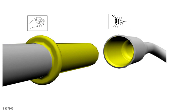
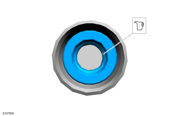
If needed, then install the turbocharger cooling
tube rubber gasket. After installing the new rubber gasket, lubricate
with clean engine coolant.
Refer to: Specifications (303-03 Engine Cooling - 3.5L EcoBoost (272kW/370PS), Specifications).
-
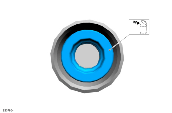
Install the new turbocharger coolant tube O-ring seals Lubricate the new O-ring seal with clean engine coolant.
Refer to: Specifications (303-03 Engine Cooling - 3.5L EcoBoost (272kW/370PS), Specifications).
-
NOTE:
Install the coolant tubes to the engine with the turbocharger.
-
NOTICE:
Do not use a metal brush damage to sealing area will result in leaks.
Carefully use a nylon brush to remove the old O-ring
residue, use brake cleaner to rinse the O-ring residue out of the
turbocharger tube to engine O-ring bores. Inspect the area for deep
scratches and gouges. Install new components if necessary.
-
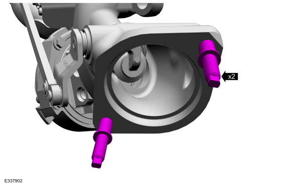
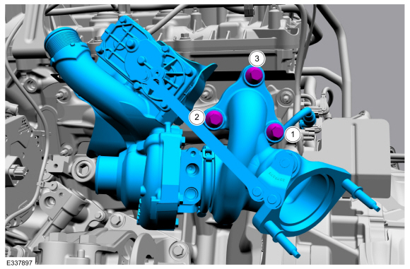
Install the turbocharger, then install and tighten
the new turbocharger retainers as indicated in the following 3 stages.
Material: Motorcraft® Metal Brake Parts Cleaner
/ PM-4-A, PM-4-B, APM-4-C
Torque:
Stage 1:
Tighten 1-3 in the sequence shown to :
18 lb.in (2 Nm)
Stage 2:
Tighten 1-3 in the sequence shown to :
38 lb.ft (51 Nm)
Stage 3:
Re-tighten 1 to :
38 lb.ft (51 Nm)
-
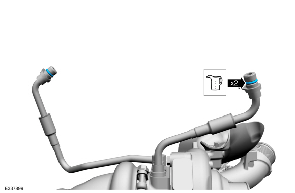
Install and tighten the turbocharger coolant return tube bolt.
Torque:
Stage 1:
Tighten to. :
89 lb.in (10 Nm)
Stage 2:
Tighten an additional 30 degrees or tighten to 16 Nm, whichever comes first. :
30°
-
Install and tighten the turbocharger coolant supply tube bolt.
Torque:
Stage 1:
Tighten to :
89 lb.in (10 Nm)
Stage 2:
Tighten an additional :
30°
-
Install the catalytic converter LH.
Refer to: Catalytic Converter LH (309-00 Exhaust System - 3.5L EcoBoost (272kW/370PS), Removal and Installation).
-
Connect the wastegate control actuator electrical connector.
-
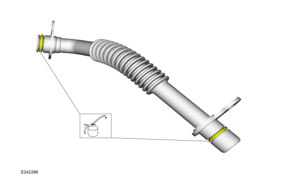
Lubricate the new turbocharger oil return tube O-ring seals with clean engine oil.
Refer to: Specifications (303-01 Engine - 3.5L V6 PowerBoost (CN))
.
-
-
NOTICE:
Do not use a metal brush, damage to the sealing area will result in leaks.
Carefully use a nylon brush to remove the old O-ring
residue, use brake cleaner to rinse the O-ring residue out of the
turbocharger and engine O-ring bores. Inspect the area for deep
scratches and gouges. Install new components if necessary.
-
Fully seat the turbocharger oil return tube into the
turbocharger and engine bore holes flush to 2.5 mm off of the mounting
surface prior to tightening the bolts. Install the new turbocharger oil
return tube, then install and tighten the turbocharger oil return tube
bolts.
Material: Motorcraft® Metal Brake Parts Cleaner
/ PM-4-A, PM-4-B, APM-4-C
Torque:
Stage 1:
Tighten to :
89 lb.in (10 Nm)
Stage 2:
Tighten an additional :
30°
-
Lubricate the new O-ring seals with clean engine oil.
Refer to: Specifications (303-01 Engine - 3.5L V6 PowerBoost (CN))
.
-
-
NOTICE:
Do not use any brushes, damage to sealing area
will result in leaks and possible internal turbo bearing damage.
Use brake cleaner on a lint free rag to remove the
O-ring residue out of the turbocharger and the engine oil filter adapter
O-ring bores. Inspect the area for deep scratches and gouges. Install
new components if necessary.
-
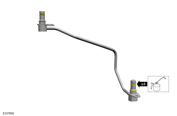
Install the oil supply tube and the bolts, by
simultaneously fully seating the oil supply tube into the turbocharger
bore hole and the engine oil filter adapter bore hole flush to 2.5 mm
off the mounting surface prior to tightening the bolts, then tighten the
bolts in the following 2 stages.
Material: Motorcraft® Metal Brake Parts Cleaner
/ PM-4-A, PM-4-B, APM-4-C
Torque:
Stage 1:
Tighten to :
89 lb.in (10 Nm)
Stage 2:
Tighten an additional :
30°
-
Attach the harness retainer.
-
Install the charge air cooler intake pipe - left side.
Refer to: Charge Air Cooler (CAC) Intake Pipe (303-12 Intake Air
Distribution and Filtering - 3.5L EcoBoost (272kW/370PS), Removal and
Installation).
-
Install the left front fender splash shield.
Refer to: Fender Splash Shield (501-02 Front End Body Panels, Removal and Installation).
-
Install the engine rear undershield.
-
Check and top off the engine oil level as needed.
Refer to: Specifications (303-01 Engine - 3.5L V6 PowerBoost (CN))
.
-
Fill the cooling system.
Refer to: Engine Cooling System Draining, Vacuum Filling and Bleeding
(303-03 Engine Cooling - 3.5L EcoBoost (272kW/370PS), General
Procedures).
-
Road test the vehicle.
Materials
Name
Specification
Motorcraft® Metal Brake Parts CleanerPM-4-A, PM-4-B, APM-4-C
-
Removal
NOTICE:
The turbocharger compressor vanes can be damaged by even the
smallest particles...
Materials
Name
Specification
Motorcraft® Metal Brake Parts CleanerPM-4-A, PM-4-B, APM-4-C
-
Removal
NOTICE:
The turbocharger compressor vanes can be damaged by even the
smallest particles...
Other information:
WARNING:
Service and handling of Pyrotechnic Components is restricted to
qualified personnel. The required qualifications vary by region. Always
observe local laws and legislative directives regarding Pyrotechnic
Components service and handling...
Removal
NOTE:
Removal steps in this procedure may contain installation details.
Remove the front bumper cover.
Refer to: Front Bumper Cover (501-19 Bumpers, Removal and Installation).
Disconnect the horn electrical connector...
 Turbocharger Coolant Supply Tube RH. Removal and Installation
 Turbocharger Oil Return Tube LH. Removal and Installation