Lincoln Navigator: Fuel Charging and Controls - Turbocharger - 3.5L EcoBoost (272kW/370PS) / Turbocharger Coolant Supply Tube RH. Removal and Installation
Materials
| Name | Specification |
|---|---|
| Motorcraft® Metal Brake Parts Cleaner PM-4-A, PM-4-B, APM-4-C |
- |
Removal
NOTICE: The turbocharger compressor vanes can be damaged by even the smallest particles. When removing any turbocharger or engine air intake system component, ensure that no debris enters the system. Failure to do so may result in damage to the turbocharger.
NOTICE: Special attention needs to be given to the sealing ports for the oil feed, the oil drain, and the coolant tubes, on turbocharged engines. The sealing ports must be totally clean and free from O-ring residue, have no damage to the sealing surface and the tubes to ensure that there are no leaks or repeat repairs.
-
Remove the turbocharger coolant return tube RH.
Refer to: Turbocharger Coolant Return Tube RH (303-04B Fuel Charging and Controls - Turbocharger - 3.5L EcoBoost (272kW/370PS), Removal and Installation).
-
NOTICE: If the 2 piece turbocharger cooling tubes are separated or the rubber gasket is leaking, then the rubber gasket must be replaced.
Remove the turbocharger coolant supply tube.
 |
-
-
Remove and discard the turbocharger coolant tube O-ring seal.
-
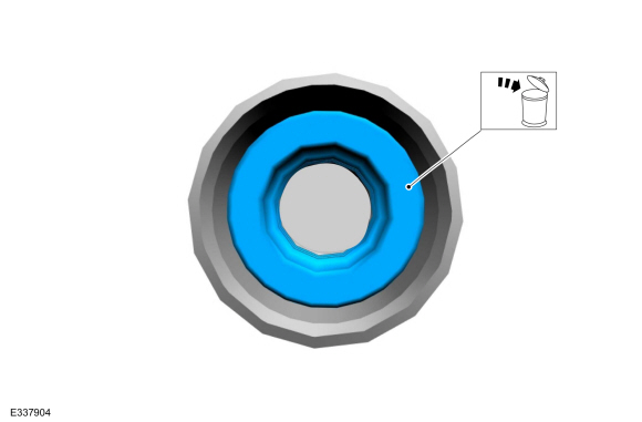
NOTICE: Do not use a metal brush, damage to sealing area will result in leaks.
Use brake cleaner and a nylon brush to clean. Clean the turbocharger coolant tube sealing surfaces. Inspect the sealing surfaces for debris or damage and make sure the retaining bracket is not bent, check for squareness of the O-ring area. Install new components if necessary.
-
Remove and discard the turbocharger coolant tube O-ring seal.
 |
-
NOTICE: If the 2 piece turbocharger cooling tubes were separated or the rubber gasket is leaking, then the rubber gasket must be replaced.
If needed, then remove and discard the rubber gasket.
 |
-
NOTICE: Do not use a metal brush, damage to sealing area will result in leaks.
If needed, inspect and clean the turbocharger cooling tube sealing surfaces, using brake cleaner and a nylon brush to clean. Install new components if necessary.
Material: Motorcraft® Metal Brake Parts Cleaner / PM-4-A, PM-4-B, APM-4-C
 |
Installation
-
-
If needed, then install the turbocharger cooling
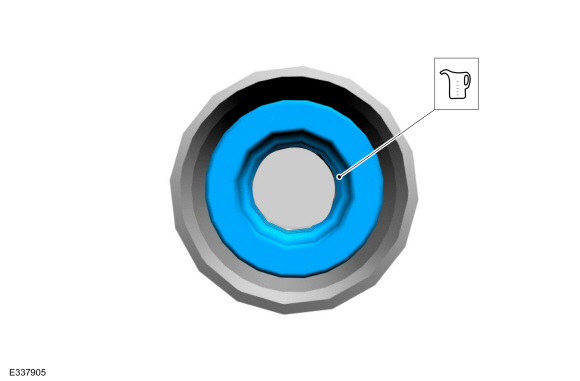
tube rubber gasket. After installing the new rubber gasket, lubricate
with clean engine coolant.
Refer to: Specifications (303-03 Engine Cooling - 3.5L EcoBoost (272kW/370PS), Specifications).
-
If needed, then install the turbocharger cooling
tube rubber gasket. After installing the new rubber gasket, lubricate
with clean engine coolant.
 |
-
Install a new turbocharger coolant return tube O-ring
seal. Lubricate the new O-ring seal with clean engine coolant.
Refer to: Specifications (303-03 Engine Cooling - 3.5L EcoBoost (272kW/370PS), Specifications).
 |
-
-
NOTICE: Do not use a metal brush, damage to sealing area will result in leaks.
Carefully use a nylon brush to remove the old O-ring residue, use brake cleaner to rinse the O-ring residue out of the turbocharger tube O-ring bore. Inspect the area for deep scratches and gouges. Install new components if necessary.
-
Install the turbocharger coolant tube.
Material: Motorcraft® Metal Brake Parts Cleaner / PM-4-A, PM-4-B, APM-4-C
-
|
-
Install the turbocharger coolant return tube RH.
Refer to: Turbocharger Coolant Return Tube RH (303-04B Fuel Charging and Controls - Turbocharger - 3.5L EcoBoost (272kW/370PS), Removal and Installation).
 Turbocharger Coolant Supply Tube LH. Removal and Installation
Materials
Name
Specification
Motorcraft® Metal Brake Parts CleanerPM-4-A, PM-4-B, APM-4-C
-
Removal
NOTICE:
The turbocharger compressor vanes can be damaged by even the
smallest particles...
 Turbocharger LH. Removal and Installation
Materials
Name
Specification
Motorcraft® High Temperature Nickel Anti-Seize LubricantXL-2
-
Motorcraft® Metal Brake Parts CleanerPM-4-A, PM-4-B, APM-4-C
-
Removal
NOTICE:
The turbocharger compressor vanes can be damaged by even the
smallest particles...
Other information:
Lincoln Navigator 2018-2026 Workshop Manual: Roof Reinforcement. Removal and Installation
Special Tool(s) / General Equipment 6.5 mm Drill Bit Self-Piercing Rivet (SPR) Remover/Installer Belt Sander Blind Rivet Gun Locking Pliers Materials Name Specification Metal Bonding AdhesiveTA-1, TA-1-B, 3M™ 08115, LORD Fusor® 108B, Henkel Teroson EP 5055 - Removal NOTE: The following procedure details re..
Lincoln Navigator 2018-2026 Workshop Manual: Tie Rod End. Removal and Installation
Special Tool(s) / General Equipment Tie Rod End Remover Removal NOTE: Removal steps in this procedure may contain installation details. NOTICE: Disconnect the battery ground cable anytime the steering linkage is being serviced or damage to the steering gear may occur resulting in steering gear replacement. Disconnect the battery ground cable...
Categories
- Manuals Home
- 4th Gen Lincoln Navigator Service Manual (2018 - 2026)
- Body and Paint
- Body Control Module (BCM). Removal and Installation
- Neutral Flat Tow Activation and Deactivation. General Procedures
- Transmission Fluid Level Check. General Procedures
- Windshield Washer Pump. Removal and Installation
Front Driveshaft. Removal and Installation
Special Tool(s) / General Equipment
Crimping ToolMaterials
Name Specification Motorcraft® Premium Long-Life GreaseXG-1-E1 ESA-M1C75-B
Removal
With the vehicle in NEUTRAL, position the vehicle on a hoist.Refer to: Jacking and Lifting (100-02 Jacking and Lifting, Description and Operation).
Remove the bolts and the transmission shield.