Lincoln Navigator: Power Steering / Steering Gear Boot. Removal and Installation
Special Tool(s) / General Equipment
| Boot Clamp Pliers |
Materials
| Name | Specification |
|---|---|
| Motorcraft® Premium Long-Life Grease XG-1-E1 |
ESA-M1C75-B |
Removal
-
Remove the tie-rod end.
Refer to: Tie Rod End (211-02 Power Steering, Removal and Installation).
-
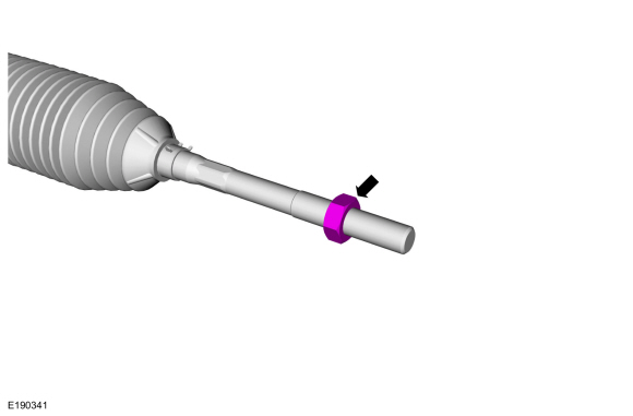
NOTE: Count and record the number of turns required to remove the outer tie-rod end jamb nut for reference during installation.
Remove the tie-rod end jamb nut.
 |
-
If equipped.
Remove the underbody shield bolts and remove the underbody shield.
 |
-
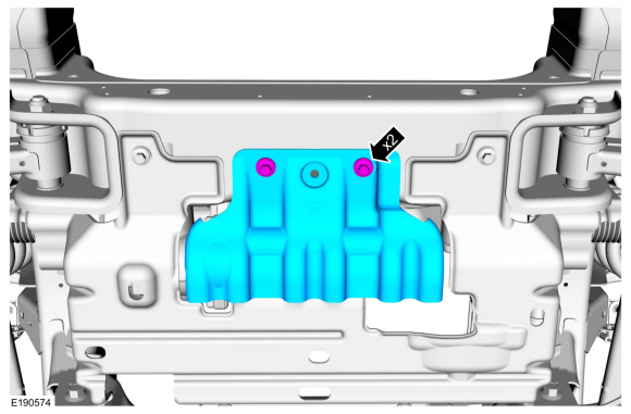
If equipped.
Remove the underbody shield bolts and remove the underbody shield.
 |
-
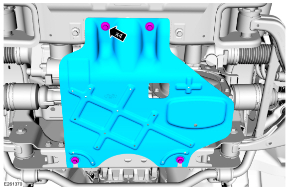
NOTE: 4WD shown, RWD similar.
If equipped.
-
Remove the forward underbody shield bolts.
-
Remove the rearward underbody shield bolts and the underbody shield.
-
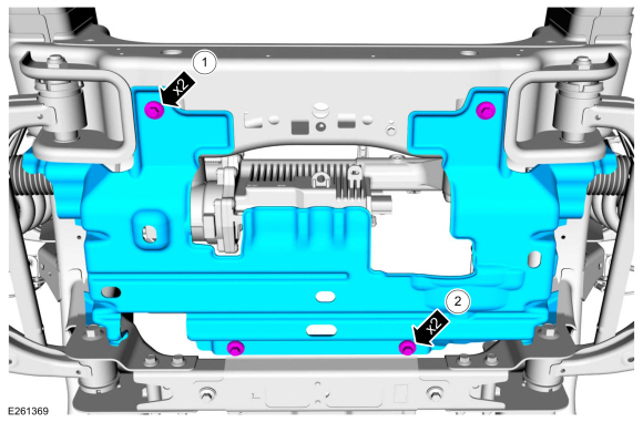
Remove the forward underbody shield bolts.
 |
-
-
Remove and discard the outer steering gear boot clamp.
-
Remove and discard the inner steering gear boot clamp.
-
Remove and discard the outer steering gear boot clamp.
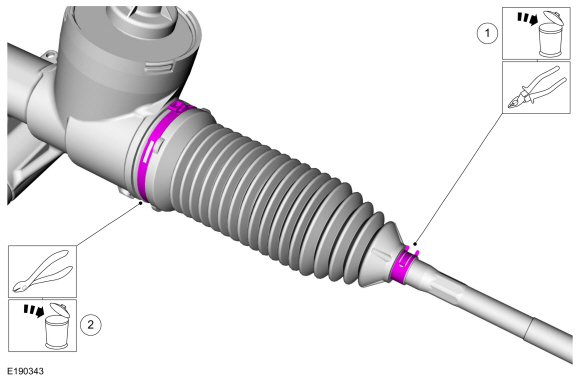 |
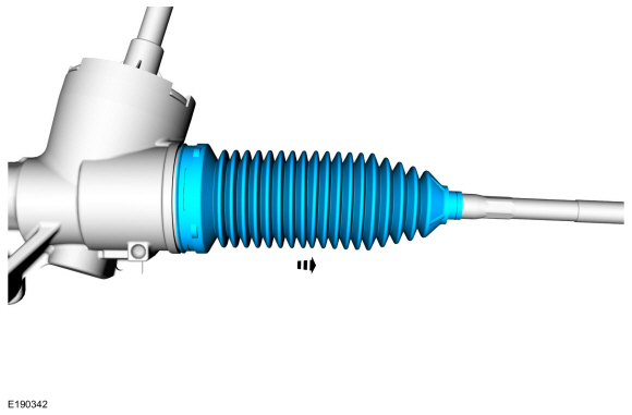
-
Remove the steering gear boot.
 |
Installation
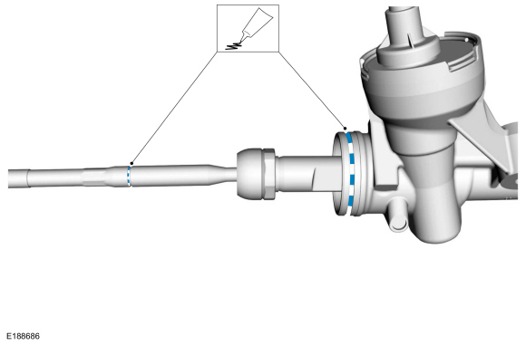
-
Apply the specified grease to the steering
gear-to-bellows boot mating surface and bellows boot groove on the inner
tie-rod.
Material: Motorcraft® Premium Long-Life Grease / XG-1-E1 (ESA-M1C75-B)
 |
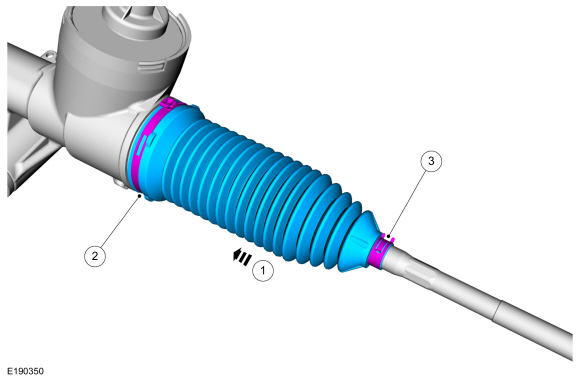
-
NOTE: LH side shown, RH similar.
-
NOTE: Make sure the steering gear bellows boot is positioned correctly over the steering gear housing bead and the groove in the inner tie rod.
Install the steering gear boot.
-
Install the new inner steering gear boot clamp.
-
Install the new outer steering gear boot clamp.
Use the General Equipment: Boot Clamp Pliers
-
 |
-
NOTE: 4WD shown, RWD similar.
If equipped.
-
Install the underbody shield and the underbody shield forward bolts.
Torque: 30 lb.ft (40 Nm)
-
Install the underbody shield rearward bolts.
Torque: 71 lb.in (8 Nm)
-
Install the underbody shield and the underbody shield forward bolts.
|
-
If equipped.
Install the underbody shield and install the underbody shield bolts.
Torque: 30 lb.ft (40 Nm)
|
-
If equipped.
Install the underbody shield and install the underbody shield bolts.
Torque: 30 lb.ft (40 Nm)
|
-
Thread the tie-rod end jam nut onto the inner tie rod.
|
-
Install the tie-rod end.
Refer to: Tie Rod End (211-02 Power Steering, Removal and Installation).
 Steering Gear. Removal and Installation
Special Tool(s) /
General Equipment
Tie Rod End Remover
Removal
NOTICE:
Disconnect the battery ground cable anytime the steering
linkage is being serviced or damage to the steering gear may occur
resulting in steering gear replacement...
 Tie Rod. Removal and Installation
Special Tool(s) /
General Equipment
Boot Clamp Pliers
Materials
Name
Specification
Motorcraft® Premium Long-Life GreaseXG-1-E1
ESA-M1C75-B
Removal
Remove the tie rod end...
Other information:
Lincoln Navigator 2018-2026 Workshop Manual: Climate Control System. Diagnosis and Testing
Diagnostic Trouble Code (DTC) Chart Diagnostics in this manual assume a certain skill level and knowledge of Ford-specific diagnostic practices. REFER to: Diagnostic Methods (100-00 General Information, Description and Operation). NOTE: Network communication or missing message Diagnostic Trouble Codes (DTCs) may result from intermittent concerns, such as damaged wiring or low battery..
Lincoln Navigator 2018-2026 Workshop Manual: Rear Bumper. Removal and Installation
Removal NOTE: Removal steps in this procedure may contain installation details. Remove the rear bumper cover. Refer to: Rear Bumper Cover (501-19 Bumpers, Removal and Installation). Disconnect the electrical connector, separate the wiring harness guides and position the wiring harness aside. With the hel..
Categories
- Manuals Home
- 4th Gen Lincoln Navigator Service Manual (2018 - 2026)
- Neutral Flat Tow Activation and Deactivation. General Procedures
- Rear View Mirrors - System Operation and Component Description. Description and Operation
- Rear Bumper. Removal and Installation
- All Terrain Control Module (ATCM). Removal and Installation
- Identification Codes. Description and Operation
Differential Case Runout Check. General Procedures
Special Tool(s) / General Equipment
 205-1016
Installer, Differential Bearing
TKIT-2014D-ROW2
TKIT-2014D-FL_ROW
 205-153
(T80T-4000-W)
205-153
(T80T-4000-W)
Handle
 205-D061
(D83T-4205-C2)
205-D061
(D83T-4205-C2)
Step Plate Dial Indicator Three Leg Puller Punch