Lincoln Navigator: Power Steering / Steering Gear. Removal and Installation
Special Tool(s) / General Equipment
| Tie Rod End Remover |
Removal
NOTICE: Disconnect the battery ground cable anytime the steering linkage is being serviced or damage to the steering gear may occur resulting in steering gear replacement.
-
If installing a new steering gear, connect the scan tool
and upload the module configuration information from the PSCM .
Refer to: Module Configuration - System Operation and Component Description (418-01B Module Configuration - Vehicles With: Over-the-Air (OTA) Programming, Description and Operation).
-
Disconnect the battery ground cable.
Refer to: Battery Disconnect and Connect (414-01 Battery, Mounting and Cables, General Procedures).
-
Using a holding device, hold the steering wheel in the straight-ahead position.
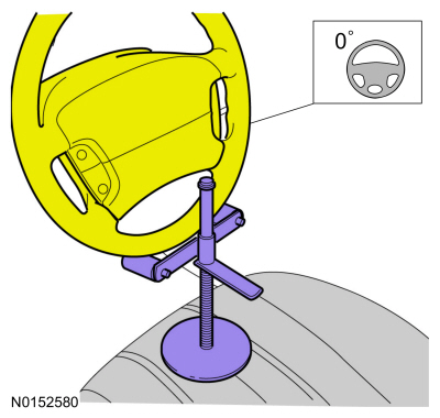 |
-
Remove the wheel and tire.
Refer to: Wheel and Tire (204-04A Wheels and Tires, Removal and Installation).
-
-
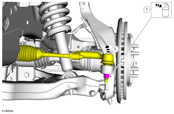
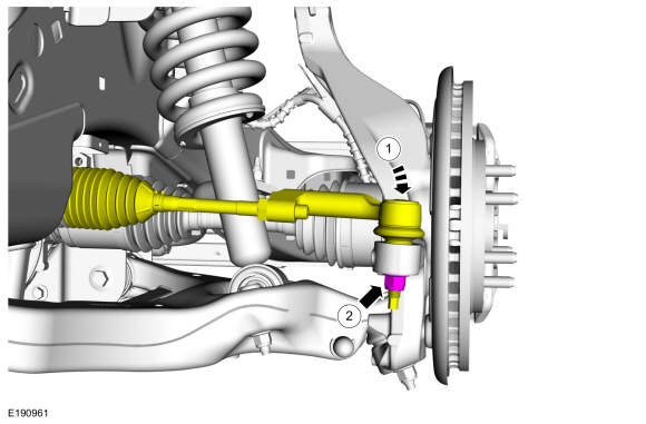
NOTE: Use the hex-holding feature to prevent the stud from turning while removing the nut.
Remove and discard the outer tie rod end nut.
-
NOTICE: Do not use a hammer to separate the outer tie-rod end from the wheel knuckle or damage to the wheel knuckle may result.
NOTICE: Use care when installing the tie rod separator or damage to the outer tie-rod end boot may occur.
Separate the outer tie rod end from the wheel knuckle.
Use the General Equipment: Tie Rod End Remover
-
 |
-
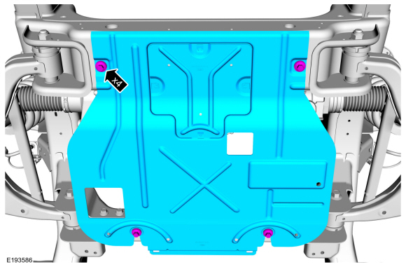
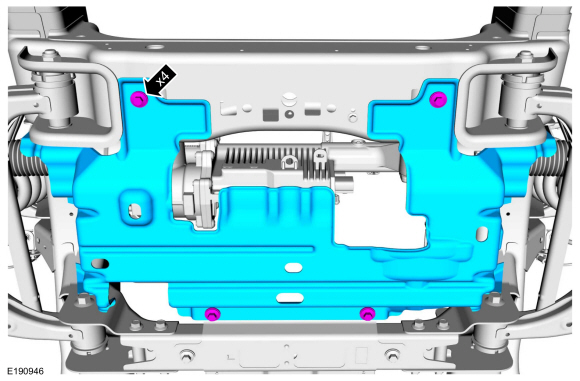
NOTE: If equipped.
Remove the underbody shield retainers and remove the underbody shield.
 |
-
NOTE: If equipped.
Remove the underbody shield retainers and remove the underbody shield.
 |
-
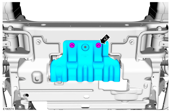
NOTE: If equipped.
NOTE: 4WD (four-wheel drive) shown, RWD (rear wheel drive) similar.
Remove the underbody shield retainers and the underbody shield.
 |
-
-
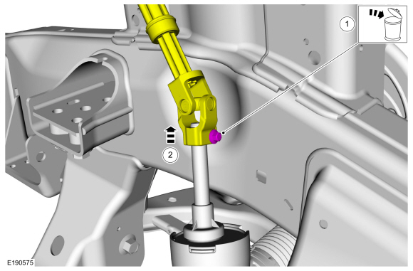
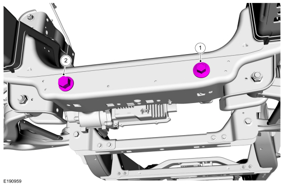
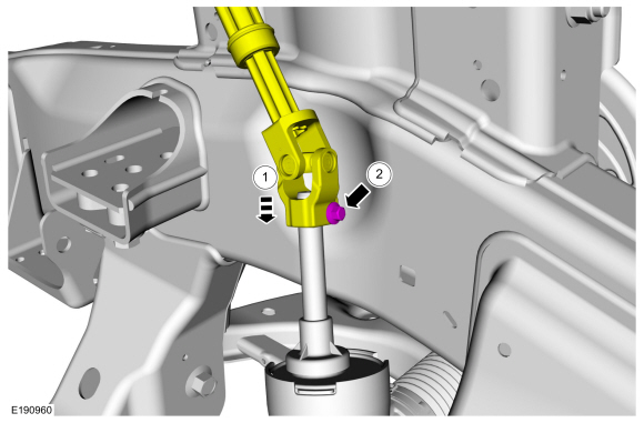
Remove and discard the steering column shaft bolt. WARNING:
Do not reuse steering column shaft bolts. This
may result in fastener failure and steering column shaft detachment or
loss of steering control. Failure to follow this instruction may result
in serious injury to vehicle occupant(s).
WARNING:
Do not reuse steering column shaft bolts. This
may result in fastener failure and steering column shaft detachment or
loss of steering control. Failure to follow this instruction may result
in serious injury to vehicle occupant(s).
-
Separate the steering column shaft u-joint from the steering gear.
-
 |
-
-
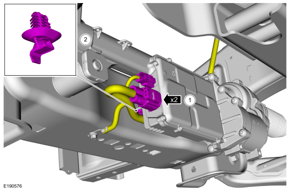
Disconnect the 2 EPAS gear electrical connectors.
-
Unclip an position the steering gear wire harness aside.
-
Disconnect the 2 EPAS gear electrical connectors.
 |
-
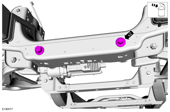
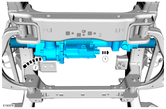
Remove and discard the 2 steering gear mounting bolts.
 |
-
-
Shift the steering gear towards the driver side of the vehicle.
-
Remove the steering gear.
-
Shift the steering gear towards the driver side of the vehicle.
 |
Installation
-
-
Position the steering gear.
-
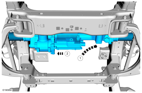
Shift the steering towards the passenger side of the vehicle.
-
Position the steering gear.
 |
-
NOTE: Driver side steering gear mounting bolt must be torqued first.
Install the 2 new steering gear mounting bolts.
Torque: 184 lb.ft (250 Nm)
 |
-
-
Connect the 2 EPAS gear electrical connectors.
-
Position the steering gear wire harness and install the retaining clip.
-
Connect the 2 EPAS gear electrical connectors.
|
-
-
Connect the steering column shaft u-joint to the steering gear.
WARNING:
Do not reuse steering column shaft bolts. This
may result in fastener failure and steering column shaft detachment or
loss of steering control. Failure to follow this instruction may result
in serious injury to vehicle occupant(s).
-
Install the new steering column shaft bolt.
Torque: 35 lb.ft (48 Nm)
-
 |
-
NOTE: If equipped.
NOTE: 4WD (four-wheel drive) shown, RWD (rear wheel drive) similar.
Install the underbody shield and the underbody shield retainers.
Torque: 30 lb.ft (40 Nm)
|
-
NOTE: If equipped.
Install the underbody shield and install the underbody shield retainers.
Torque: 30 lb.ft (40 Nm)
|
-
NOTE: If equipped.
Install the underbody shield and install the underbody shield retainers.
Torque: 30 lb.ft (40 Nm)
|
-
-
Connect the outer tie rod end to the wheel knuckle.
-
NOTE: Use the hex-holding feature to prevent the stud from turning while installing the nut.
Install the new outer tie rod end nut.
Torque: 66 lb.ft (90 Nm)
-
Connect the outer tie rod end to the wheel knuckle.
 |
-
Install the wheel and tire.
Refer to: Wheel and Tire (204-04A Wheels and Tires, Removal and Installation).
-
Connect the battery ground cable.
Refer to: Battery Disconnect and Connect (414-01 Battery, Mounting and Cables, General Procedures).
-
When installing a new steering gear, it must be
configured (using vehicle as-built data or module configuration
information retrieved earlier in this procedure). Connect a scan tool
and follow the scan tool instructions.
Refer to: Module Configuration - System Operation and Component Description (418-01B Module Configuration - Vehicles With: Over-the-Air (OTA) Programming, Description and Operation).
-
Check and if necessary, adjust front toe.
Refer to: Front Toe Adjustment (204-00 Suspension System - General Information, General Procedures).
 Power Steering. Diagnosis and Testing
Diagnostic Trouble Code (DTC) Chart
Diagnostics in this manual assume a certain skill level and knowledge of Ford-specific diagnostic practices. REFER to: Diagnostic Methods (100-00 General Information, Description and Operation)...
 Steering Gear Boot. Removal and Installation
Special Tool(s) /
General Equipment
Boot Clamp Pliers
Materials
Name
Specification
Motorcraft® Premium Long-Life GreaseXG-1-E1
ESA-M1C75-B
Removal
Remove the tie-rod end...
Other information:
Lincoln Navigator 2018-2026 Workshop Manual: Roof Reinforcement. Removal and Installation
Special Tool(s) / General Equipment 6.5 mm Drill Bit Self-Piercing Rivet (SPR) Remover/Installer Belt Sander Blind Rivet Gun Locking Pliers Materials Name Specification Metal Bonding AdhesiveTA-1, TA-1-B, 3M™ 08115, LORD Fusor® 108B, Henkel Teroson EP 5055 - Removal NOTE: The following procedure details re..
Lincoln Navigator 2018-2026 Workshop Manual: Front Door Glass Run and Bracket. Removal and Installation
Removal NOTE: LH side shown, RH side similar. Remove the front door latch. Refer to: Front Door Latch (501-14 Handles, Locks, Latches and Entry Systems, Removal and Installation). Remove the exterior front door handle reinforcement. Detach the cable from the exterior front door handle reinforcement. Remove the cable ey..
Categories
- Manuals Home
- 4th Gen Lincoln Navigator Service Manual (2018 - 2026)
- Transmission Fluid Level Check. General Procedures
- Head Up Display (HUD) Module Calibration. General Procedures
- Body and Paint
- Remote Function Actuator (RFA) Module. Removal and Installation
- Rear Bumper. Removal and Installation
Rear Stabilizer Bar Link. Removal and Installation
Removal
NOTE: Removal steps in this procedure may contain installation details.
With the vehicle in NEUTRAL, position it on a hoist.Refer to: Jacking and Lifting (100-02 Jacking and Lifting, Description and Operation).
NOTE: Use the hex-holding feature to prevent the stud from turning while removing the nut.
Remove and discard the 2 rear stabilizer bar link nuts and remove the rear stabilizer bar link.Torque: 46 lb.ft (63 Nm)
