Lincoln Navigator: Charging System - General Information / Charging System - 3.5L EcoBoost (272kW/370PS). Diagnosis and Testing
Diagnostic Trouble Code (DTC) Chart
Diagnostics in this manual assume a certain skill level and knowledge of Ford-specific diagnostic practices.
REFER to: Diagnostic Methods (100-00 General Information, Description and Operation).
| Module | DTC | Description | Action |
|---|---|---|---|
| BCM | B11D9:16 | Vehicle Battery: Circuit Voltage Below Threshold | GO to Pinpoint Test A |
| BCM | B11D9:16 | Vehicle Battery: Circuit Voltage Below Threshold | GO to Pinpoint Test B |
| BCM | B11DB:02 | Battery Monitoring Module 'A': General Signal Failure | GO to Pinpoint Test E |
| BCM | B11DB:08 | Battery Monitoring Module 'A': Bus Signal/Message Failures | GO to Pinpoint Test E |
| BCM | B11DB:09 | Battery Monitoring Module 'A': Component Failures | GO to Pinpoint Test E |
| BCM | B11DB:11 | Battery Monitoring Module 'A': Circuit Short To Ground | GO to Pinpoint Test E |
| BCM | B11DB:49 | Battery Monitoring Module 'A': Internal Electronic Failure | GO to Pinpoint Test I |
| BCM | B11DB:55 | Battery Monitoring Module 'A': Not Configured | GO to Pinpoint Test J |
| BCM | B11DB:9A | Battery Monitoring Module 'A': Component or System Operating Conditions | GO to Pinpoint Test E |
| BCM | B130C:12 | Load Shed Control: Circuit Short To Battery | GO to Pinpoint Test E |
| BCM | B130C:14 | Load Shed Control: Circuit Short To Ground Or Open | GO to Pinpoint Test E |
| PCM | P0562:00 | System Voltage Low: No Sub Type Information | GO to Pinpoint Test B |
| PCM | P0563:00 | System Voltage High: No Sub Type Information | GO to Pinpoint Test A |
| PCM | P065B:00 | Generator 'A' Control Circuit Range/Performance: No Sub Type Information | GO to Pinpoint Test B |
| PCM | P065C:00 | Generator 'A' Mechanical Performance: No Sub Type Information | GO to Pinpoint Test B |
| PCM | P0A3B:00 | Generator 'A' Over Temperature: No Sub Type Information | GO to Pinpoint Test H |
| PCM | U012D:00 | Lost Communication With Generator 'A' Control Module: No Sub Type Information | GO to Pinpoint Test F |
| PCM | U042E:00 | Invalid Data Received From Generator 'A' Control Module: No Sub Type Information | GO to Pinpoint Test F |
Global Customer Symptom Code (GCSC) Chart
Diagnostics in this manual assume a certain skill level and knowledge of Ford-specific diagnostic practices.
| Symptom | Action |
|---|---|
| Comfort & Entertainment > Audio > Radio FM > Sound Quality | GO to Pinpoint Test D |
| Driver Aid & Information > Warning Indicators/Messages/Chimes > Charging System > Stays On | GO to Pinpoint Test A |
| Driver Aid & Information > Warning Indicators/Messages/Chimes > Charging System > Stays On | GO to Pinpoint Test B |
| Driver Aid & Information > Warning Indicators/Messages/Chimes > Charging System > Stays On | GO to Pinpoint Test K |
| Start/Run/Move > Noise > Running/Standing > Always | GO to Pinpoint Test C |
| Start/Run/Move > Noise > Running/Standing > Always | GO to Pinpoint Test G |
Symptom Chart(s)
Diagnostics
in this manual assume a certain skill level and knowledge of
Ford-specific diagnostic practices. For information about these
practices,
REFER to: Diagnostic Methods (100-00 General Information, Description and Operation).
| Symptom | Possible Sources | Action |
|---|---|---|
|
|
|
|
|
|
|
|
|
|
|
|
|
|
|
Pinpoint Tests
|
NOTE: Diagnostic Trouble Code (DTC ) P0563 can be set if the vehicle has been recently jump started or the battery has been recently charged. The battery may become discharged due to excessive load(s) on the charging system from aftermarket accessories or if vehicle accessories have been operating for an extended period of time without the engine running. Refer to Wiring Diagrams Cell 12 for schematic and connector information. Normal Operation and Fault Conditions With the engine running, the charging system supplies voltage to the battery and the vehicle electrical system through the BJB and battery B+ cable. The voltage that is supplied to the vehicle electrical system is used for the operation of the various vehicle systems and modules. Many modules monitor this voltage and if it rises above or below their calibrated setpoints, a DTC sets. DTC Fault Trigger Conditions
Possible Sources
Visual Inspection and Pre-checks
NOTE: Make sure battery voltage is greater than 12.2 volts prior to and during this pinpoint test. NOTE: Do not have a battery charger attached during vehicle testing. |
||||||||||||||||||||||
| A1 PERFORM INSPECTION AND VERIFICATION | ||||||||||||||||||||||
Was an obvious cause for an observed or reported concern found?
|
||||||||||||||||||||||
| A2 MONITOR THE GENERATOR VOLTAGE DESIRED (GENVDSD) PID (PARAMETER IDENTIFICATION) | ||||||||||||||||||||||
Does the PID indicate 15.9 volts or less?
|
||||||||||||||||||||||
| A3 COMPARE THE GENERATOR VOLTAGE DESIRED (GENVDSD) PID (PARAMETER IDENTIFICATION) WITH BATTERY VOLTAGE | ||||||||||||||||||||||
Is the recorded battery voltage within ±0.5 volt of the PID ?
|
||||||||||||||||||||||
| A4 CHECK THE VOLTAGE DROP IN THE VEHICLE GROUNDS | ||||||||||||||||||||||
Is the voltage drop less than 0.5 volt?
|
||||||||||||||||||||||
| A5 MONITOR THE GENERATOR VOLTAGE DESIRED (GENVDSD) PID (PARAMETER IDENTIFICATION) WHILE COMMANDED | ||||||||||||||||||||||
Is the recorded battery voltage within ±0.5 volt of the PID ?
|
||||||||||||||||||||||
| A6 CHECK THE GENERATOR OUTPUT | ||||||||||||||||||||||
Is the recorded battery voltage within ±0.5 volt of the PID?
|
||||||||||||||||||||||
| A7 COMPARE THE SUPPLY VOLTAGE (VPWR) PID (PARAMETER IDENTIFICATION) TO BATTERY VOLTAGE | ||||||||||||||||||||||
Does the PID accurately display battery voltage within ±0.5 volt of the recorded battery voltage?
|
||||||||||||||||||||||
| A8 CHECK PCM SUPPLY VOLTAGE CIRCUITS | ||||||||||||||||||||||
Are the voltages within 0.5 volt of the recorded battery voltage?
|
||||||||||||||||||||||
| A9 CHECK FOR CORRECT PCM OPERATION | ||||||||||||||||||||||
Is the concern still present?
|


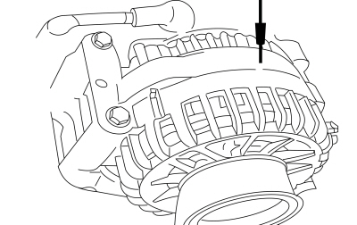 Generator case

 Click here to access Guided Routine (PCM).
|
Refer to Wiring Diagrams Cell 12 for schematic and connector information. Normal Operation and Fault Conditions With the engine running, the charging system supplies voltage to the battery and the vehicle electrical system through the BJB and battery B+ cable. The PCM monitors this B+ voltage through PCM VPWR circuits. If the charging system voltage drops 1.5 volts or more below the generator voltage desired (GENVDSD), the DTC sets and the charging system MIL illuminates after 30 seconds. DTC Fault Trigger Conditions
Possible Sources
Visual Inspection and Pre-checks
NOTE: Make sure battery voltage is greater than 12.2 volts prior to and during this pinpoint test. NOTE: Do not have a battery charger attached during vehicle testing. |
||||||||||||||||||||||
| B1 PERFORM INSPECTION AND VERIFICATION | ||||||||||||||||||||||
Was an obvious cause for an observed or reported concern found?
|
||||||||||||||||||||||
| B2 RETRIEVE DIAGNOSTIC TROUBLE CODES (DTCS) | ||||||||||||||||||||||
Is DTC P065B, P065C, U012D or U042E present?
|
||||||||||||||||||||||
| B3 CHECK THE GENERATOR CONNECTIONS | ||||||||||||||||||||||
Is the voltage within 0.5 volt of the recorded battery voltage?
|
||||||||||||||||||||||
| B4 CHECK THE VOLTAGE DROP IN THE GENERATOR B+ CIRCUIT | ||||||||||||||||||||||
Is the voltage drop less than 0.5 volt?
|
||||||||||||||||||||||
| B5 CHECK THE VOLTAGE IN THE VEHICLE GROUNDS | ||||||||||||||||||||||
Is voltage less than 0.5V?
|
||||||||||||||||||||||
| B6 MONITOR THE GENERATOR VOLTAGE DESIRED (GENVDSD) PID WHILE COMMANDED | ||||||||||||||||||||||
Is the recorded battery voltage within ±0.5 volt of the PID ?
|
||||||||||||||||||||||
| B7 COMPARE THE SUPPLY VOLTAGE (VPWR) PID (PARAMETER IDENTIFICATION) TO BATTERY VOLTAGE | ||||||||||||||||||||||
Does the PID accurately display battery voltage within ±0.5 volt of the recorded battery voltage?
|
||||||||||||||||||||||
| B8 CHECK PCM VOLTAGE SUPPLY CIRCUITS | ||||||||||||||||||||||
Are the voltages within 0.5 volt of the recorded battery voltage?
|
||||||||||||||||||||||
| B9 CHECK PCM GROUND FOR HIGH RESISTANCE | ||||||||||||||||||||||
Does the PID read within ±0.5 volt of battery voltage with accessory loads on and off?
|
||||||||||||||||||||||
| B10 MONITOR THE SUPPLY VOLTAGE (VPWR) PID (PARAMETER IDENTIFICATION) | ||||||||||||||||||||||
Does the PID stay within 0.5 volt of the recorded battery voltage when the engine Revolutions Per Minute (RPM) are increased?
|
||||||||||||||||||||||
| B11 CHECK GENERATOR CLUTCH OPERATION | ||||||||||||||||||||||
Is the generator clutch OK?
|
||||||||||||||||||||||
| B12 CHECK FOR CORRECT PCM (POWERTRAIN CONTROL MODULE) OPERATION | ||||||||||||||||||||||
Is the concern still present?
|
|
Normal Operation and Fault Conditions The generator is belt-driven by the engine FEAD system. There are several sources of generator noise which include bearing noise, electrical fault noise, generator or belt pulley misalignment. A generator with certain types of diode or stator failures can also produce an audible noise. Possible Sources
Visual Inspection and Pre-checks
|
||||
| C1 CHECK FOR ACCESSORY DRIVE BELT NOISE AND LOOSE MOUNTING BRACKETS | ||||
Is the accessory drive OK?
|
||||
| C2 CHECK THE GENERATOR MOUNTING | ||||
Is the generator mounted correctly?
|
||||
| C3 CHECK THE GENERATOR FOR NOISE | ||||
Is the generator the noise source?
|
||||
| C4 CHECK GENERATOR CLUTCH OPERATION | ||||
Is the generator clutch OK?
|
|
NOTE: If the Original Equipment Manufacturer (OEM) Audio Control Module (ACM) has been replaced with an aftermarket unit, the vehicle may not pass this test. Return the vehicle to Original Equipment Manufacturer (OEM) condition before following this pinpoint test. NOTE: If the engine is operated at greater than 2,000 Revolutions Per Minute (RPM) momentarily, the generator self-excites. Make sure when the generator is disconnected the engine rpm stays below 2,000 Revolutions Per Minute (RPM). If it rises above 2,000 Revolutions Per Minute (RPM), turn the ignition to the OFF position and start the test over again. NOTE: Inspect for any aftermarket accessories that have been added to the vehicle. Check the wiring for these accessories and be sure they have not been attached to the generator circuits and are positioned away from the generator wiring. Normal Operation and Fault Conditions The generator radio suppression equipment reduces interference transmitted through the speakers by the vehicle electrical system. Possible Sources
Visual Inspection and Pre-checks
|
||||
| D1 VERIFY THE GENERATOR IS THE SOURCE OF THE AUDIO SYSTEM INTERFERENCE | ||||
Is the interference present with the generator disconnected?
|
|
Refer to Wiring Diagrams Cell 12 for schematic and connector information. Normal Operation and Fault Conditions The BCM monitors the battery state of charge using the battery monitoring sensor attached to the negative battery cable. Battery voltage is hardwired to the battery monitoring sensor and data is transferred from the battery monitoring sensor to the BCM via a LIN circuit. DTC Fault Trigger Conditions
Possible Sources
Visual Inspection and Pre-checks
NOTE: Make sure battery voltage is greater than 12.2 volts prior to and during this pinpoint test. NOTE: Do not have a battery charger attached during vehicle testing. |
||||||||||||||||||||||||
| E1 CHECK ELECTRICAL CONNECTOR CONDITION | ||||||||||||||||||||||||
Are all connectors clean and connected properly?
|
||||||||||||||||||||||||
| E2 RETRIEVE BCM (BODY CONTROL MODULE) DIAGNOSTIC TROUBLE CODES (DTCS) | ||||||||||||||||||||||||
Did the DTC return?
|
||||||||||||||||||||||||
| E3 CHECK THE BATTERY MONITORING SENSOR SUPPLY VOLTAGE | ||||||||||||||||||||||||
Is the voltage within 0.5 volt of the recorded battery voltage?
|
||||||||||||||||||||||||
| E4 CHECK THE BATTERY MONITORING SENSOR LIN (LOCAL INTERCONNECT NETWORK) CIRCUIT FOR A SHORT TO VOLTAGE | ||||||||||||||||||||||||
Is any voltage present?
|
||||||||||||||||||||||||
| E5 CHECK THE BATTERY MONITORING SENSOR LIN (LOCAL INTERCONNECT NETWORK) CIRCUIT FOR A SHORT TO GROUND | ||||||||||||||||||||||||
Is the resistance greater than 10,000 ohms?
|
||||||||||||||||||||||||
| E6 CHECK THE BATTERY MONITORING SENSOR LIN (LOCAL INTERCONNECT NETWORK) CIRCUIT FOR AN OPEN | ||||||||||||||||||||||||
Is the resistance less than 3 ohms?
|
||||||||||||||||||||||||
| E7 CHECK FOR CORRECT BCM (BODY CONTROL MODULE) OPERATION | ||||||||||||||||||||||||
Is the concern still present?
|

|
Refer to Wiring Diagrams Cell 12 for schematic and connector information. DTC Fault Trigger Conditions
Possible Sources
Visual Inspection and Pre-checks
NOTE: Make sure battery voltage is greater than 12.2 volts prior to and during this pinpoint test. NOTE: Do not have a battery charger attached during vehicle testing. |
||||||||||
| F1 CHECK THE BATTERY CONDITION | ||||||||||
Does the battery pass the condition test?
|
||||||||||
| F2 IS DTC U012D PRESENT WITHOUT U0284 OR U0285 OR U042E OR U0645? | ||||||||||
Is DTC U012D without U0284 or U0285 or U042E or U0645 present?
|
||||||||||
| F3 CHECK FOR VOLTAGE ON THE ALTERNATOR B+ | ||||||||||
Did battery voltage rise after engine started?
|
||||||||||
| F4 CHECK THE ALTERNATOR B+ CONNECTION | ||||||||||
Does C102B equal to battery voltage?
|
||||||||||
| F5 CHECK THE LIN (LOCAL INTERCONNECT NETWORK) LINE FOR SHORT TO OTHER PINS | ||||||||||
Is the resistance less than10,000 ohms?
|
||||||||||
| F6 CHECK THE GENERATOR FOR CAUSE OF SHORT | ||||||||||
Is resistance less the 10,000 ohms?
|
||||||||||
| F7 DISCONNECT GENERATOR LIN (LOCAL INTERCONNECT NETWORK) CONNECTION AND CHECK FOR RESISTANCE | ||||||||||
Is the resistance less than 3 ohms?
|
||||||||||
| F8 CHECK PIN FIT FOR CONNECTORS C175B PIN 49 AND C102B-1 | ||||||||||
Is the pin ok.
|
||||||||||
| F9 CHECK FOR PCM ABILITY TO CONTROL THE ALTERNATOR | ||||||||||
Is the battery voltage within 14.7+/-0.5 volts?
|
||||||||||
| F10 WIGGLE TEST WIRING | ||||||||||
Does the voltage change or is the DTC U012D or U042E set while wiggling the wires?
|

|
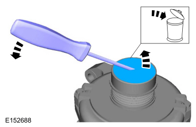
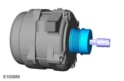
Normal Operation and Fault Conditions The generator clutch allows the generator rotor to continue to
rotate when the engine or FEAD
system slows. The clutch should slip freely and smoothly in a
clockwise direction. It should not rotate freely in the counterclockwise
direction. A loose FEAD
belt or a weak or binding tensioner can cause the pulley to overheat.
REFER to: Charging System - 3.5L EcoBoost (272kW/370PS) - System
Operation and Component Description (414-00 Charging System - General
Information, Description and Operation). The generator is belt-driven by the engine FEAD system. There are several sources of generator noise which include bearing noise, electrical fault noise, generator or belt pulley misalignment. A generator with certain types of diode or stator failures can also produce an audible noise. Possible Sources
Visual Inspection and Pre-checks
|
||||
| G1 INSPECT THE GENERATOR CLUTCH | ||||
Is there evidence of heat damage?
|
||||
| G2 CHECK THE GENERATOR CLUTCH FOR SMOOTH ROTATION | ||||
Does the clutch shaft rotation feel rough or seized?
|
||||
| G3 CHECK FOR REVERSE ROTATION RESISTANCE | ||||
Is there some resistance (a spring feel)?
|
||||
| G4 CHECK FOR REVERSE ROTATION | ||||
Does the clutch shaft rotate freely?
|
|
Normal Operation and Fault Conditions DTC Fault Trigger Conditions
Possible Sources
|
||||||
| H1 RETRIEVE PCM (POWERTRAIN CONTROL MODULE) DIAGNOSTIC TROUBLE CODES (DTCS) | ||||||
Is DTC P0A3B recorded?
|
|
Normal Operation and Fault Conditions DTC Fault Trigger Conditions
Possible Sources
|
||||||
| I1 RETRIEVE BCM (BODY CONTROL MODULE) DIAGNOSTIC TROUBLE CODES (DTCS) | ||||||
Is DTC B11DB:49 recorded?
|
|
Normal Operation and Fault Conditions CHECK the vehicle service history for recent service actions related to this module. DTC Fault Trigger Conditions
Possible Sources
|
||||||
| J1 RETRIEVE BCM (BODY CONTROL MODULE) DIAGNOSTIC TROUBLE CODES (DTCS) | ||||||
Is DTC B11DB:55 recorded?
|
|
Normal Operation and Fault Conditions RETRIEVE DTC from all modules. If any DTC s are found, Refer to DTC
Chart in this section. If no DTC s are found, REFER to: Instrumentation,
Message Center and Warning Chimes - Vehicles With: Head Up Display
(HUD) (413-01 Instrumentation, Message Center and Warning Chimes,
Diagnosis and Testing). Possible Sources
|
| Diagnostic steps are not provided for this symptom or DTC. REFER to: Diagnostic Methods (100-00 General Information, Description and Operation). |


Other information:
Lincoln Navigator 2018-2026 Workshop Manual: Air Deflector. Removal and Installation
Special Tool(s) / General Equipment Rivet Gun Electric Drill 6 mm Drill Bit Punch Vacuum Cleaner Removal NOTE: Removal steps in this procedure may contain installation details. Fully open the roof opening panel glass. On both sides. Drill the rivets and position the air de..
Lincoln Navigator 2018-2026 Workshop Manual: Battery Charging. General Procedures
Charging NOTE: Batteries will discharge due to normal parasitic key off-loads when the vehicle is on a dealer lot or parked by the customer for an extended period of time. Vehicles still in dealer inventory or in long-term storage may be driven short distances with heavy electrical loads. Over a period of time (30 days or more), this could result in vehicles having shallow or deeply..
Categories
- Manuals Home
- 4th Gen Lincoln Navigator Service Manual (2018 - 2026)
- Rear View Mirrors - System Operation and Component Description. Description and Operation
- SYNC Module [APIM]. Removal and Installation
- Body Control Module (BCM). Removal and Installation
- Telematics Control Unit (TCU) Module. Removal and Installation
- Windshield Washer Pump. Removal and Installation
Axle Tube Bearing. Removal and Installation
Special Tool(s) / General Equipment
 205-123
(T78P-1177-A)
205-123
(T78P-1177-A)
Installer, Axle Shaft Oil Seal
 308-047
(T77F-1102-A)
308-047
(T77F-1102-A)
Remover, Bearing Cup Slide Hammer