Lincoln Navigator: Fuel Charging and Controls - Turbocharger - 3.5L EcoBoost (272kW/370PS) / Turbocharger Oil Supply Tube RH. Removal and Installation
Materials
| Name | Specification |
|---|---|
| Motorcraft® Metal Brake Parts Cleaner PM-4-A, PM-4-B, APM-4-C |
- |
Removal
NOTICE: The turbocharger compressor vanes can be damaged by even the smallest particles. When removing any turbocharger or engine air intake system component, ensure that no debris enters the system. Failure to do so may result in damage to the turbocharger.
NOTICE: Special attention needs to be given to the sealing ports for the oil feed, the oil drain, and the coolant lines, on turbocharged engines. The sealing ports must be totally clean and free from O-ring residue, have no damage to the sealing surface and the lines to ensure that there are no leaks or repeat repairs.
-
With the vehicle in NEUTRAL, position it on a hoist.
Refer to: Jacking and Lifting (100-02 Jacking and Lifting, Description and Operation).
-
Remove the engine rear undershield.
-
Remove the right front fender splash shield.
Refer to: Fender Splash Shield (501-02 Front End Body Panels, Removal and Installation).
-
Remove the charge air cooler intake pipe - right side.
Refer to: Charge Air Cooler (CAC) Intake Pipe (303-12 Intake Air Distribution and Filtering - 3.5L EcoBoost (272kW/370PS), Removal and Installation).
-
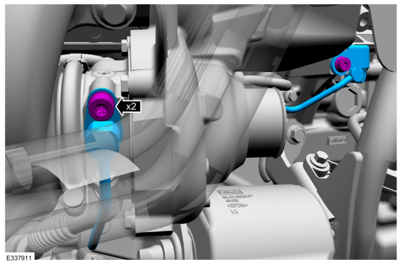
Remove the turbocharger oil supply tube bolts, then remove and discard the turbocharger oil supply tube.
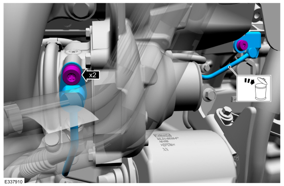 |
-
Remove and discard the turbocharger fitting and oil filter assembly from the engine block.
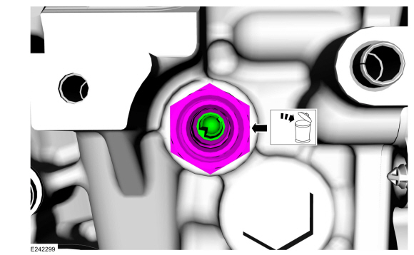 |
Installation
-
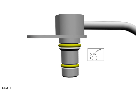
Lubricate the new turbocharger fitting and oil filter assembly O-ring seal with clean engine oil.
Refer to: Specifications (303-01 Engine - 3.5L EcoBoost (BM)) .
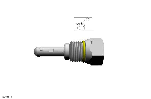 |
-
-
NOTICE: Do not use any brushes, damage to sealing area will result in leaks and possible internal turbo bearing damage.
Use brake cleaner on a lint free rag to remove the O-ring residue out of the turbocharger fitting to engine block O-ring bore. Inspect the area for deep scratches and gouges. Install new components if necessary.
Material: Motorcraft® Metal Brake Parts Cleaner / PM-4-A, PM-4-B, APM-4-C
-
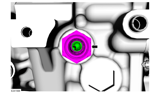
Install and tighten the new turbocharger fitting, oil filter assembly.
Torque: 24 lb.ft (32 Nm)
-
 |
-
Lubricate the new turbocharger oil supply tube O-ring seals with clean engine oil.
Refer to: Specifications (303-01 Engine - 3.5L EcoBoost (BM)) .
 |
-
-
NOTICE: Do not use any brushes, damage to sealing area will result in leaks and possible internal turbo bearing damage.
Use brake cleaner on a lint free rag to remove the O-ring residue out of the turbocharger and the engine oil filter adapter O-ring bores. Inspect the area for deep scratches and gouges. Install new components if necessary.
-
Install the oil supply tube and the bolts, by
simultaneously fully seating the oil supply tube into the turbocharger
bore hole and the engine oil filter adapter bore hole flush to 2.5 mm
off the mounting surface prior to tightening the bolts, then tighten the
bolts in the following 2 stages.
Material: Motorcraft® Metal Brake Parts Cleaner / PM-4-A, PM-4-B, APM-4-C
Torque:
Stage 1: Tighten to : 89 lb.in (10 Nm)
Stage 2: Tighten an additional : 30°
-
 |
-
Install the charge air cooler intake pipe - right side.
Refer to: Charge Air Cooler (CAC) Intake Pipe (303-12 Intake Air Distribution and Filtering - 3.5L EcoBoost (272kW/370PS), Removal and Installation).
-
Install the right fender splash shield.
Refer to: Fender Splash Shield (501-02 Front End Body Panels, Removal and Installation).
-
Install the engine rear undershield.
-
Check and top off the engine oil level as needed.
Refer to: Specifications (303-01 Engine - 3.5L EcoBoost (BM)) .
 Turbocharger Oil Supply Tube LH. Removal and Installation
Materials
Name
Specification
Motorcraft® Metal Brake Parts CleanerPM-4-A, PM-4-B, APM-4-C
-
Removal
NOTICE:
The turbocharger compressor vanes can be damaged by even the
smallest particles...
 Turbocharger RH. Removal and Installation
Materials
Name
Specification
Motorcraft® High Temperature Nickel Anti-Seize LubricantXL-2
-
Motorcraft® Metal Brake Parts CleanerPM-4-A, PM-4-B, APM-4-C
-
Removal
NOTICE:
The turbocharger compressor vanes can be damaged by even the
smallest particles...
Other information:
Lincoln Navigator 2018-2026 Workshop Manual: Anti-Lock Brake System (ABS) and Stability Control - Overview. Description and Operation
Overview The ABS and stability control systems are comprised of the following subsystems which assist the driver in maintaining control of the vehicle: ABS Auto hold (EPB ) EBB Drive away release (EPB ) EBD EPB control ESC Hill descent control Hill start assist RSC ..
Lincoln Navigator 2018-2026 Workshop Manual: Intermediate Speed Sensor B (ISSB). Removal and Installation
Removal Remove the main control valve body. Refer to: Main Control Valve Body (307-01 Automatic Transmission - 10-Speed Automatic Transmission – 10R80, Removal and Installation). Remove the intermediate speed sensor B. Slide the plastic lock to the unlocked position. While pressing the plastic tab, disconnect the electrical connector. ..
Categories
- Manuals Home
- 4th Gen Lincoln Navigator Service Manual (2018 - 2026)
- Power Running Board (PRB). Diagnosis and Testing
- Front Bumper Cover. Removal and Installation
- Brake Service Mode Activation and Deactivation. General Procedures
- Transmission Fluid Drain and Refill. General Procedures
- Identification Codes. Description and Operation
Wheel to Hub Runout Minimization. General Procedures
Check
NOTE: Wheel-to-hub optimization is important. Clearance between the wheel and hub can be used to offset or neutralize the Road Force® or run-out of the wheel and tire assembly. For every 0.001 inch of wheel-to-hub clearance, the Road Force® can be affected between 1 and 3 pounds depending on the tire stiffness.
NOTE: The example below illustrates how the clearance between the wheel and the hub can be used to offset the high spot of radial run-out or Road Force®. Following the procedure will make sure of the best optimization.
Position the wheel and tire assembly on the vehicle so that the high spot location of radial run-out or Road Force® is at the 6 o'clock position and