Lincoln Navigator: Fuel Charging and Controls - Turbocharger - 3.5L EcoBoost (272kW/370PS) / Turbocharger Oil Supply Tube LH. Removal and Installation
Materials
| Name | Specification |
|---|---|
| Motorcraft® Metal Brake Parts Cleaner PM-4-A, PM-4-B, APM-4-C |
- |
Removal
NOTICE: The turbocharger compressor vanes can be damaged by even the smallest particles. When removing any turbocharger or engine air intake system component, ensure that no debris enters the system. Failure to do so may result in damage to the turbocharger.
NOTICE: Special attention needs to be given to the sealing ports for the oil feed, the oil drain, and the coolant lines, on turbocharged engines. The sealing ports must be totally clean and free from O-ring residue, have no damage to the sealing surface and the lines to ensure that there are no leaks or repeat repairs.
-
Remove the engine rear undershield.
-
Remove the left front fender splash shield.
Refer to: Fender Splash Shield (501-02 Front End Body Panels, Removal and Installation).
-
Remove the charge air cooler intake pipe - left side.
Refer to: Charge Air Cooler (CAC) Intake Pipe (303-12 Intake Air Distribution and Filtering - 3.5L EcoBoost (272kW/370PS), Removal and Installation).
-
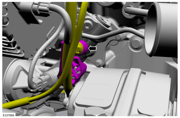
Detach the harness retainer, then move the harness out of the way.
 |
-
NOTE: The left turbocharger oil supply tube does not have a turbocharger oil supply filter.
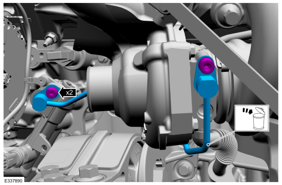
Remove the turbocharger oil supply tube bolts, then remove and discard the turbocharger oil supply tube.
 |
Installation
-
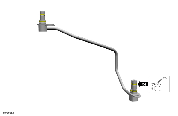
Lubricate the new O-ring seals with clean engine oil.
Refer to: Specifications (303-01 Engine - 3.5L V6 PowerBoost (CN)) .
 |
-
-
NOTICE: Do not use any brushes, damage to sealing area will result in leaks and possible internal turbo bearing damage.
Use brake cleaner on a lint free rag to remove the O-ring residue out of the turbocharger and the engine oil filter adapter O-ring bores. Inspect the area for deep scratches and gouges. Install new components if necessary.
-
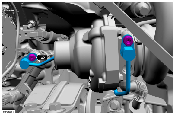
Install the oil supply tube and the bolts, by
simultaneously fully seating the oil supply tube into the turbocharger
bore hole and the engine oil filter adapter bore hole flush to 2.5 mm
off the mounting surface prior to tightening the bolts, then tighten the
bolts in the following 2 stages.
Material: Motorcraft® Metal Brake Parts Cleaner / PM-4-A, PM-4-B, APM-4-C
Torque:
Stage 1: Tighten to : 89 lb.in (10 Nm)
Stage 2: Tighten an additional : 30°
-
 |
-
Attach the harness retainer.
|
-
Install the charge air cooler intake pipe - left side.
Refer to: Charge Air Cooler (CAC) Intake Pipe (303-12 Intake Air Distribution and Filtering - 3.5L EcoBoost (272kW/370PS), Removal and Installation).
-
Install the left front fender splash shield.
Refer to: Fender Splash Shield (501-02 Front End Body Panels, Removal and Installation).
-
Install the engine rear undershield.
-
Check and top off the engine oil level as needed.
Refer to: Specifications (303-01 Engine - 3.5L V6 PowerBoost (CN)) .
 Turbocharger Oil Return Tube RH. Removal and Installation
Materials
Name
Specification
Motorcraft® Metal Brake Parts CleanerPM-4-A, PM-4-B, APM-4-C
-
Removal
NOTICE:
The turbocharger compressor vanes can be damaged by even the
smallest particles...
 Turbocharger Oil Supply Tube RH. Removal and Installation
Materials
Name
Specification
Motorcraft® Metal Brake Parts CleanerPM-4-A, PM-4-B, APM-4-C
-
Removal
NOTICE:
The turbocharger compressor vanes can be damaged by even the
smallest particles...
Other information:
Lincoln Navigator 2018-2026 Workshop Manual: Fuel System. Diagnosis and Testing
Symptom Chart(s) Symptom Chart: Fuel System Diagnostics in this manual assume a certain skill level and knowledge of Ford-specific diagnostic practices. REFER to: Diagnostic Methods (100-00 General Information, Description and Operation). for information regarding Ford-specific diagnostic practices...
Lincoln Navigator 2018-2026 Workshop Manual: Specifications
Reference Value Symptom Chart NOTE: The Reference Value Symptom Chart provides guidance in selecting the appropriate parameter identification (PID) or measured signal related to the fault area. Select a symptom from the symptom chart along with the category number and go to the PID/Measured Signal Chart...
Categories
- Manuals Home
- 4th Gen Lincoln Navigator Service Manual (2018 - 2026)
- Remote Function Actuator (RFA) Module. Removal and Installation
- Vehicle Dynamics Control Module (VDM). Removal and Installation
- Rear View Mirrors - System Operation and Component Description. Description and Operation
- SYNC Module [APIM]. Removal and Installation
- Identification Codes. Description and Operation
Rear Drive Axle and Differential. Diagnosis and Testing
Symptom Chart(s)
Diagnostics in this manual assume a certain skill level and knowledge of Ford-specific diagnostic practices.
REFER to: Diagnostic Methods (100-00 General Information, Description and Operation).
Symptom Chart - Differential
Symptom Chart - Differential
Condition Actions Axle overheating GO to Pinpoint Test A Broken gear teeth on the ring gear or pinion GO to Pi