Lincoln Navigator: Bumpers / Front Bumper Cover. Removal and Installation
Removal
NOTE: Removal steps in this procedure may contain installation details.
-
Remove the front wheels and tires.
Refer to: Wheel and Tire (204-04A Wheels and Tires, Removal and Installation).
-
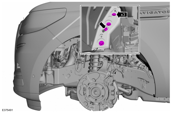
Remove the front bumper cover lower trim pins.
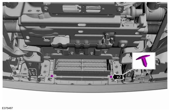 |
-
On both sides.
Remove the fender liner screws.
Torque: 15 lb.in (1.7 Nm)
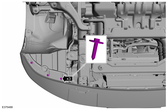 |
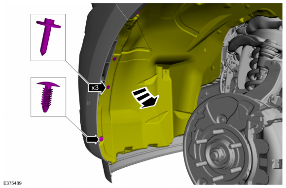
-
On both sides.
Remove the screws, the trim pin and position the fender liner aside.
Torque: 15 lb.in (1.7 Nm)
 |
-
-
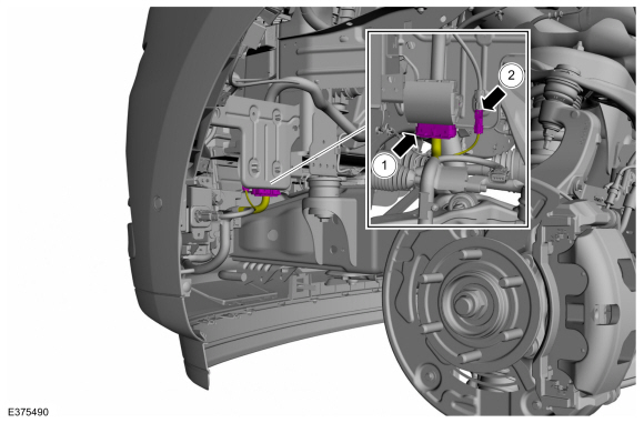
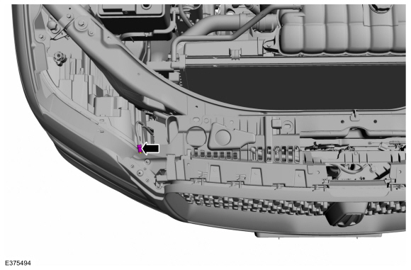
Disconnect the front bumper cover harness electrical connector.
-
If equipped.
Disconnect the front camera harness electrical connector.
-
Disconnect the front bumper cover harness electrical connector.
 |
-
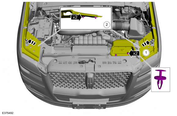
On both sides.
Remove the front bumper cover to fender bracket bolts and release the tab.
Torque: 36 lb.in (4.1 Nm)
 |
-
-
Remove the push pins and position the air cleaner panel aside.
-
Release the clips and position the cowl filler panel aside.
-
Remove the push pins and position the air cleaner panel aside.
 |
-
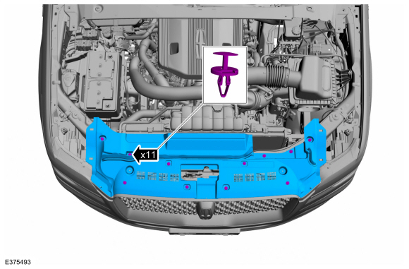
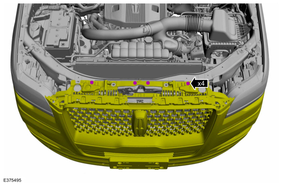
Remove the push pins and the radiator sight shield.
 |
-
If equipped.
Disconnect the front camera washer hose coupling.
 |
-
Remove the screws.
Torque: 22 lb.in (2.5 Nm)
 |
-
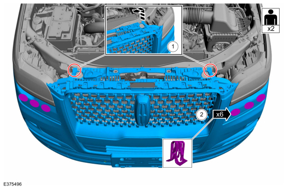
NOTE: This step requires the aid of another technician.
Remove the front bumper cover.
-
Lift the upper bumper cover off the locating pins.
-
Release the clips and remove the front bumper cover.
-
Lift the upper bumper cover off the locating pins.
 |
Installation
-
To install, reverse the removal procedure.
Vehicles With: 360 Degree Camera
-
Align the 360° cameras.
Refer to: 360 Degree View Camera Alignment (413-13B Parking Aid - Vehicles With: Parking Aid Camera, General Procedures).
Vehicles With: Front Parking Aid
-
Check the alignment of the front parking aid sensors.
Refer to: Azimuth System Check (413-13A Parking Aid, General Procedures).
Refer to: Elevation System Check (413-13A Parking Aid, General Procedures).
-
If any sensor fails the check, diagnose the sensor fault.
Refer to: Parking Aid (413-13A Parking Aid, Diagnosis and Testing).
Vehicles With: Active Park Assist
-
If replacing the front bumper cover.
Check the alignment of the front active park assist sensors.
Refer to: Azimuth System Check (413-13C Parking Aid - Vehicles With: Active Park Assist, General Procedures).
-
If any sensor fails the check, diagnose the sensor fault.
Refer to: Parking Aid (413-13C Parking Aid - Vehicles With: Active Park Assist, Diagnosis and Testing).
 Front Bumper. Removal and Installation
Removal
NOTE:
Removal steps in this procedure may contain installation details.
Remove the front bumper cover.
Refer to: Front Bumper Cover (501-19 Bumpers, Removal and Installation)...
 Rear Bumper. Removal and Installation
Removal
NOTE:
Removal steps in this procedure may contain installation details.
Remove the rear bumper cover.
Refer to: Rear Bumper Cover (501-19 Bumpers, Removal and Installation)...
Other information:
Lincoln Navigator 2018-2026 Workshop Manual: Fuel System Pressure Check. General Procedures
Special Tool(s) / General Equipment 310-D009 (D95L-7211-A) Fuel Pressure Test Kit Check NOTE: This Fuel System Pressure Check is for the low pressure side of the system. Release the fuel system pressure. Refer to: Fuel System Pressure Release (310-00 Fuel System - General Information - 3...
Lincoln Navigator 2018-2026 Workshop Manual: Floor Console. Removal and Installation
Special Tool(s) / General Equipment Interior Trim Remover Removal NOTE: Removal steps in this procedure may contain installation details. All vehicles or Front floor console Remove the RH floor console vent cover...
Categories
- Manuals Home
- 4th Gen Lincoln Navigator Service Manual (2018 - 2026)
- Body and Paint
- Liftgate Trim Panel. Removal and Installation
- Head Up Display (HUD) Module Calibration. General Procedures
- All Terrain Control Module (ATCM). Removal and Installation
- SYNC Module [APIM]. Removal and Installation
Front Stabilizer Bar Link. Removal and Installation
Removal
NOTICE: Suspension fasteners are critical parts that affect the performance of vital components and systems. Failure of these fasteners may result in major service expense. Use the same or equivalent parts if replacement is necessary. Do not use a replacement part of lesser quality or substitute design. Tighten fasteners as specified.
NOTE: Removal steps in this procedure may contain installation details.
With the vehicle in NEUTRAL, position it on a hoist.Refer to: Jacking and Lifting (100-02 Jacking and Lifting, Description and Operation).
NOTICE: Do not use power tools to remove or install the stabilizer bar