Lincoln Navigator: Engine - 3.5L EcoBoost (272kW/370PS) / Engine. Assembly
Special Tool(s) /
General Equipment
 |
100-002
(TOOL-4201-C)
Holding Fixture with Dial Indicator Gauge |
 |
205-142
(T80T-4000-J)
Installer, Differential Bearing Cone |
 |
205-149
(T80T-4000-R)
Installer, Spindle Bearing |
 |
205-153
(T80T-4000-W)
Handle |
 |
303-102
Installer, Crankshaft Pulley |
 |
303-1246
Engine Spreader Bar
TKIT-2006UF-FLM
TKIT-2006UF-ROW |
 |
303-1247
VCT Spark Plug Tube Seal Remover and Installer
TKIT-2006UF-FLM
TKIT-2006UF-ROW |
 |
303-1250
Seal Installer, Rear Main
TKIT-2006UFFLM |
 |
303-1251
Installer, Front Seal
TKIT-2006UF-FLM
TKIT-2006UF-ROW |
 |
303-1567
Sizer, Teflon Seal
TKIT-2010C-FLM |
 |
303-1654
Lift Eyes |
 |
303-1655
Tool, Camshaft Holding |
 |
303-1663
Installer, VDOP Seal |
 |
307-399
Alignment Pins, Transmission Fluid Pump
TKIT-2002N-DEW
TKIT-2000AP-FLM/LM |
 |
310-207
Installer, Fuel Injector Seal Assembly
TKIT-2009A-FLM |
| Strap Wrench |
| Floor Crane |
| Mounting Stand |
| Hose Clamp Remover/Installer |
| Round-Ended Steel Rule |
| Piston Ring Compressor |
Materials
| Name |
Specification |
Motorcraft® High Performance Engine RTV Silicone
TA-357 |
WSE-M4G323-A6
|
Motorcraft® Silicone Gasket Remover
ZC-30-A, AZC-30-C |
-
|
Motorcraft® Metal Surface Prep Wipes
ZC-31-B |
-
|
Motorcraft® Yellow Prediluted Antifreeze/Coolant
VC-13DL-G |
WSS-M97B57-A2
|
Motorcraft® Metal Brake Parts Cleaner
PM-4-A, PM-4-B, APM-4-C |
-
|
NOTICE:
During engine repair procedures, cleanliness is extremely
important. Any foreign material, including any material created while
cleaning gasket surfaces that enters the oil passages, coolant passages
or the oil pan, may cause engine failure.
NOTICE:
The TC compressor vanes can be damaged by even the smallest particles.
When removing any TC or engine air intake system component, ensure that
no debris enters the system. Failure to do so may result in damage to
the TC .
NOTICE:
Special attention needs to be given to the sealing ports for the
oil feed, the oil drain, and the coolant tubes, on turbocharged
engines. The sealing ports must be totally clean and free from O-ring
residue, have no damage to the sealing surface and the tubes to ensure
that there are no leaks or repeat repairs.
NOTICE:
During the removal or installation of components, cap, tape or
otherwise appropriately protect all openings and tubes/fittings to
prevent the ingress of dirt or other contamination. Remove caps, tape
and other protective materials prior to installation.
NOTE:
Assembly of the engine requires various inspections/measurements
of the engine components. These inspections/measurements will aid in
determining if the engine components will require replacement. Refer to
Section 303-00.
-
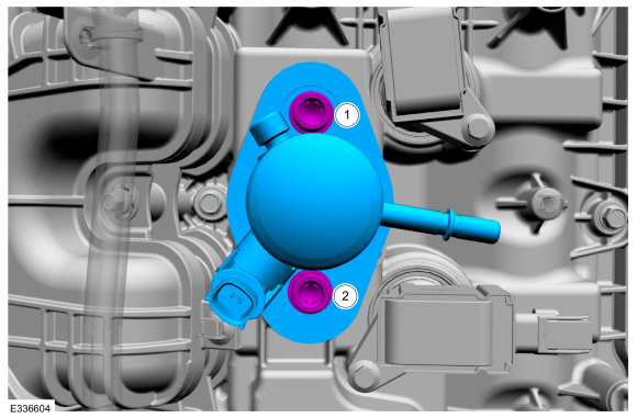
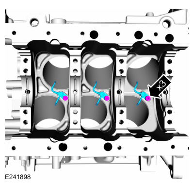
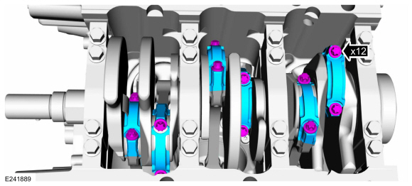
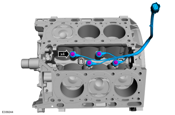
Install the piston cooling jets and bolts into the cylinder block.
Torque:
Stage 1:
71 lb.in (8 Nm)
Stage 2:
30°
-
NOTE:
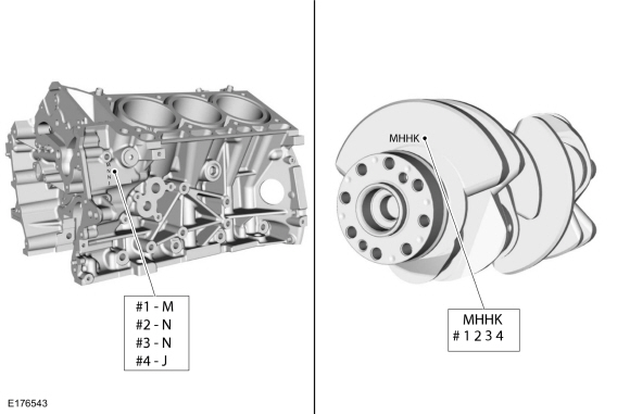
This step is for selecting the correct main bearings.
NOTE:
The #1 main bearing is at the front of the engine block.
-
Select the crankshaft main bearings for each crankshaft journal.
-
Record the code that is on the cylinder block face.
-
Record the code that is on the crankshaft flange.
-
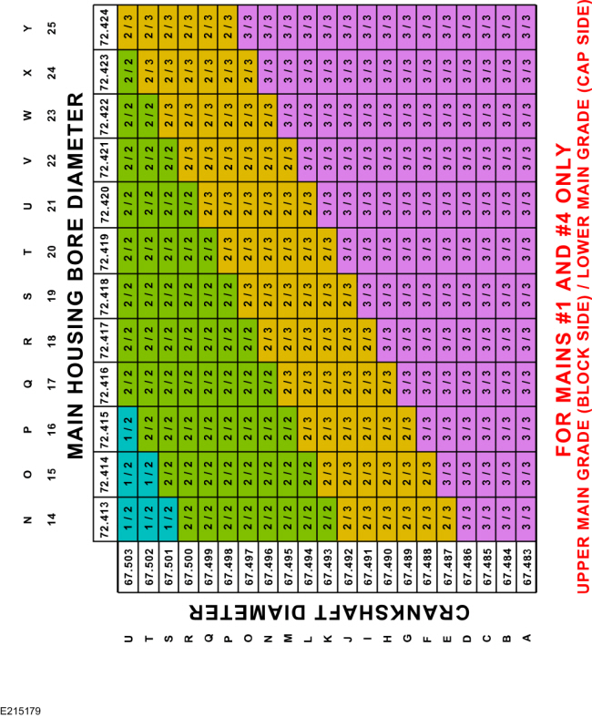
The first letter is for main No. 1 and the next letters are for mains 2, 3 and 4.
 |
|
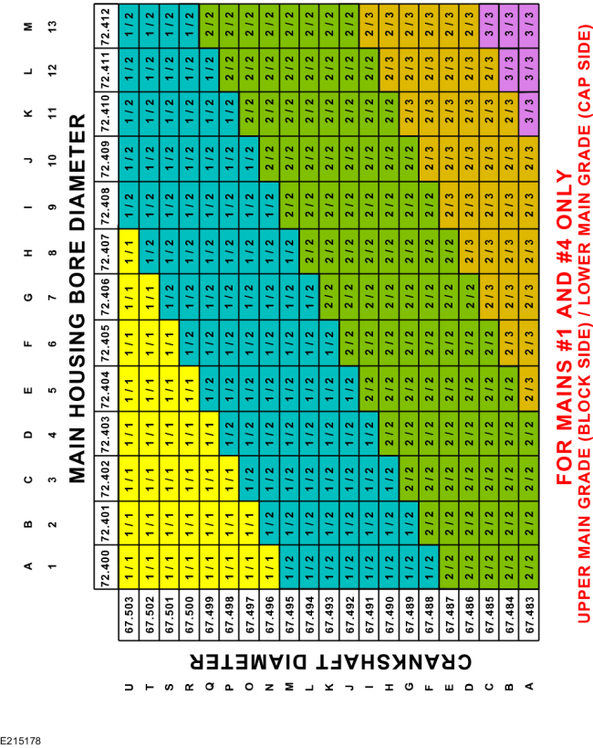
-
NOTE:
This chart is continued in the next step.
NOTE:
This chart is for selecting main bearings 1 and 4 only.
-
Using the data recorded earlier and the Bearing Select
Fit Chart, Standard Bearings, determine the required bearing grade for
main bearings 1 and 4.
-
Read the first letter of the engine block main bearing
code and the first letter of the crankshaft main bearing code.
-
Read down the column below the engine block main bearing
code letter and across the row next to the crankshaft main bearing code
letter, until the 2 intersect. This is the required bearing grade(s)
for the No. 1 crankshaft main bearing.
-
As an example, if the engine block code letter is "M"
and the crankshaft code letter is "M", the correct bearing grade for
this main bearing is a "2" for the upper bearing and a "2" for the lower
bearing.
-
Repeat the above steps using the fourth letter of the block and crankshaft codes to select the No. 4 bearing.
-
NOTE:
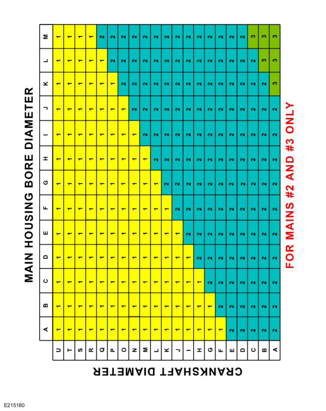
This chart is for selecting main bearings 1 and 4 only.
-
NOTE:
This chart is continued in the next step.
NOTE:
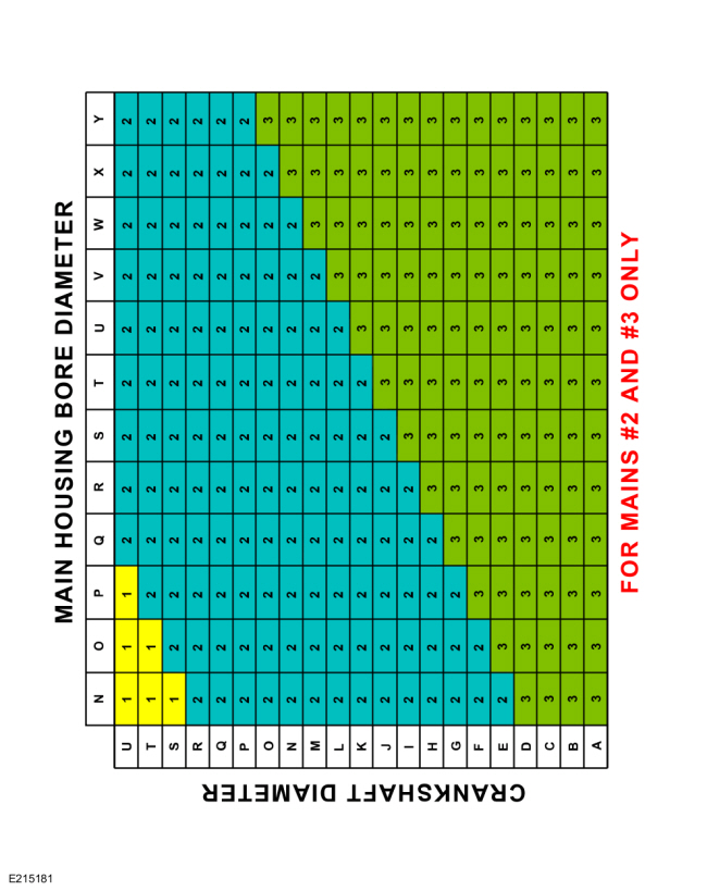
This chart is for selecting main bearings 2 and 3 only.
-
Main housing bore diameter.
-
Crankshaft diameter.
-
Using the data recorded earlier and the Bearing Select
Fit Chart, Standard Bearings, determine the required bearing grade for
main bearings 2 and 3.
-
Read the second letter of the engine block main bearing
code and the second letter of the crankshaft main bearing code.
-
Read down the column below the engine block main bearing
code letter and across the row next to the crankshaft main bearing code
letter, until the 2 intersect. This is the required bearing grade for
the No. 2 crankshaft main bearing.
-
As an example, if the engine block code letter is "N"
and the crankshaft code letter is "H", the correct bearing grade for
this main bearing is "2".
-
Repeat the above steps using the third letter of the block and crankshaft codes to select the No. 3.
-
NOTE:
This chart is for selecting main bearings 2 and 3 only.
-
NOTICE:
The rod cap installation must keep the same orientation
as marked during disassembly or engine damage may occur.
Using the original connecting rod cap bolts, install the connecting rod caps and bolts.
Torque:
Stage 1:
17 lb.ft (23 Nm)
Stage 2:
32 lb.ft (43 Nm)
Stage 3:
90°
-
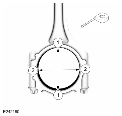
Measure the connecting rod large end bore in 2 directions.
-
-
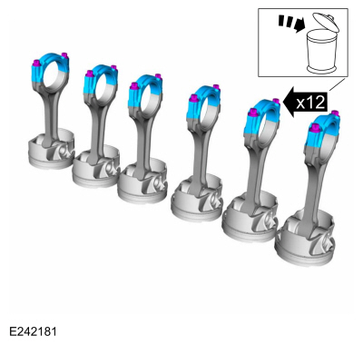
Remove the bolts and the rod cap.
-
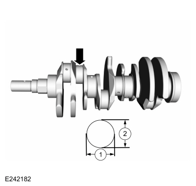
Measure each of the crankshaft connecting rod bearing journal diameters in at least 2 directions.
-
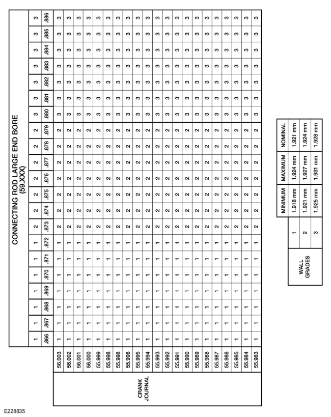
Using the chart, select the correct connecting rod bearings for each crankshaft connecting rod journal.
-
NOTE:
Before assembling the cylinder block, all sealing
surfaces must be free of chips, dirt, paint and foreign material. Also,
make sure the coolant and oil passages are clear.
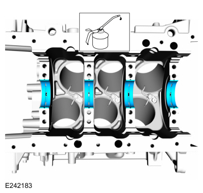
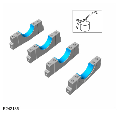
Lubricate the upper crankshaft main bearings with clean engine oil and install in the cylinder block.
Refer to: Specifications (303-01)
.
-
NOTE:
Do not install the upper thrust bearings until the crankshaft is installed.
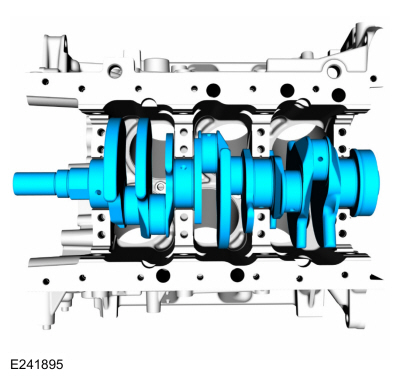
NOTE:
Lubricate the thrust surfaces of the crankshaft with clean engine oil.
Install the crankshaft.
Refer to: Specifications (303-01)
.
-
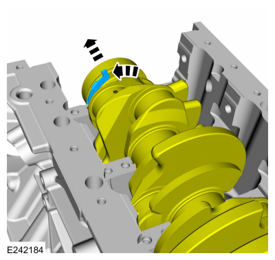
NOTE:
Make sure the side of the thrust washer, with the wide oil grooves, faces the crankshaft thrust surface.
Push the crankshaft rearward and install the rear crankshaft
upper thrust washer at the back of the No. 4 rear bulkhead.
-
NOTE:
Make sure the side of the thrust washer, with the wide oil grooves, faces the crankshaft thrust surface.
Push the crankshaft forward and install the front crankshaft
upper thrust washer at the front of the No. 4 rear bulkhead.
-
Lubricate the crankshaft lower main bearings with clean
engine oil and install them into the main bearing caps. Check seating
and squareness of the bearings to make sure of proper seating in caps.
Refer to: Specifications (303-01)
.
-
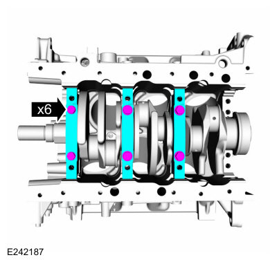
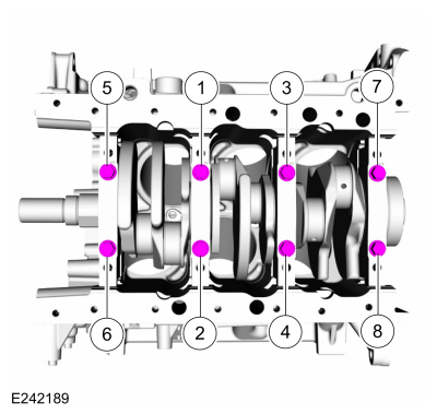
Position the No. 1, No. 2 and No. 3 main bearing caps on the
cylinder block and, keeping the caps as square as possible, alternately
draw the caps down evenly using the new bolts until the main bearing
caps are seated.
-
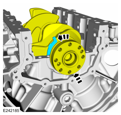
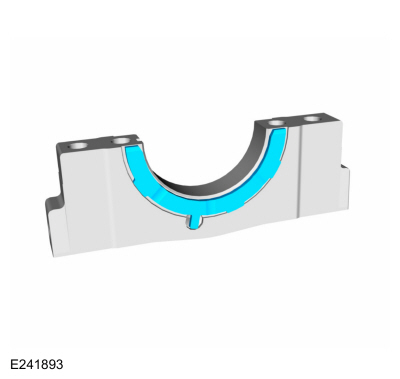
NOTE:
Make sure the side of the thrust washer, with the wide oil grooves, faces the crankshaft thrust surface.
NOTE:
To aid in assembly, apply petroleum jelly to the back of the crankshaft thrust washer.
Install the lower crankshaft thrust washer to the back side
of the No. 4 rear main bearing cap, with the tab aligned with the cutout
in the main bearing cap.
-
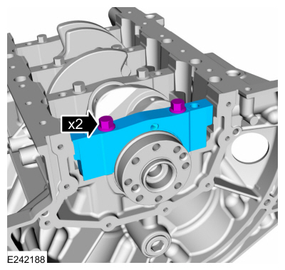
Position main bearing cap No. 4 on the cylinder block and
keeping the cap as square as possible, alternately draw the cap down
evenly using the new bolts until the main bearing cap is seated.
-
NOTE:
While tightening the main bearing vertical bolts, push
the crankshaft forward and the No. 4 main bearing cap rearward to seat
the crankshaft thrust washers.
Tighten the main bearing bolts.
Torque:
Stage 1:
20 lb.ft (27 Nm)
Stage 2:
180°
-
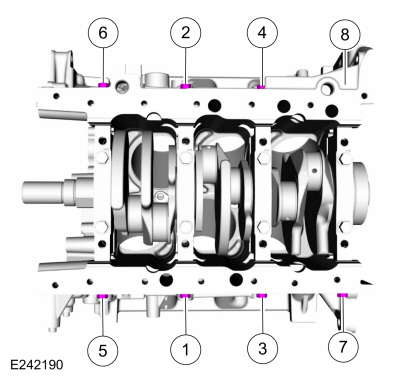
Install the new main bearing cap side bolts.
Torque:
Stage 1:
33 lb.ft (45 Nm)
Stage 2:
90°
-
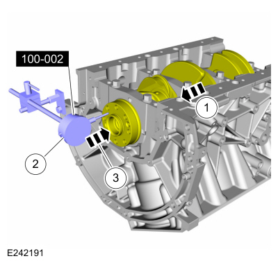
-
Position the crankshaft to the rear of the cylinder block.
Use Special Service Tool: 100-002
(TOOL-4201-C)
Holding Fixture with Dial Indicator Gauge.
-
Zero the Dial Indicator Gauge.
-
Move the crankshaft to the front of the cylinder block. Measure and record the crankshaft end play.
-
NOTICE:
The rod cap installation must keep the same orientation
as marked during disassembly or engine damage may occur.
-
Prepare the connecting rod and cap
-
Insert the new bolts in the rod cap.
-
Insert the upper and lower rod bearings into the rod and cap.
-
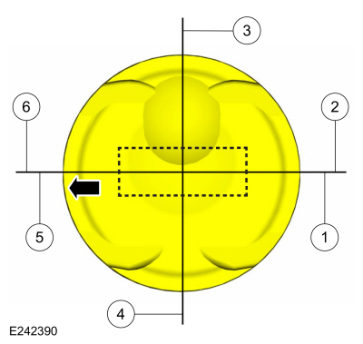
NOTE:
The piston compression upper and lower ring should be
installed with the "O" mark on the ring face pointing up toward the top
of the piston.
NOTE:
The arrow on the top of the piston indicates the front of the engine.
-
Center line of the piston parallel to the wrist pin bore.
-
Upper compression ring gap location.
-
Upper oil control segment ring gap location.
-
Lower oil control segment ring gap location.
-
Lower compression ring gap location.
-
Spacer oil control ring gap location.
 |
|
-
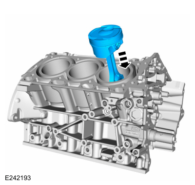
NOTICE:
Be sure not to scratch the cylinder wall or crankshaft
journal with the connecting rod. Be sure not to damage or bend the
piston oil cooling jets when seating the connecting rod on the
crankshaft journal. Push the piston down until the connecting rod
bearing seats on the crankshaft journal.
NOTE:
Lubricate the pistons, piston rings, connecting rod
bearings and the entire cylinder bores with clean engine oil.
NOTE:
Make sure the piston rings are positioned to specifications for installation. Refer to Piston in this section.
NOTE:
If the piston and or connecting rod are being installed
new, the piston rod orientation marks and the arrow on the top of the
dome of the piston should be facing toward the front of the engine
block.
NOTE:
If the piston and connecting rod are to be reinstalled,
they must be installed in the same orientation as disassembled.
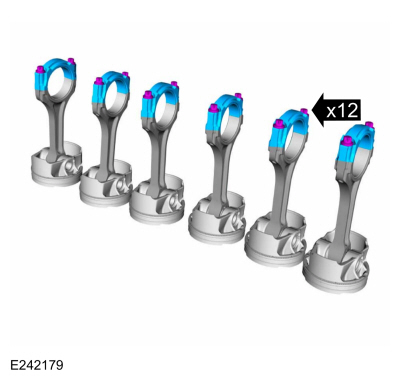
Using the Piston Ring Compressor, install the piston and
connecting rod assemblies. Repeat until all 6 piston assemblies are
installed.
Refer to: Specifications (303-01)
.
Use the General Equipment: Piston Ring Compressor
 |
|
-
NOTICE:
The rod cap installation must keep the same orientation
as marked during disassembly or engine damage may occur.
NOTE:
After installation of each piston, connecting rod, rod
cap and bolts, rotate the crankshaft to verify smooth operation.
Install the connecting rod cap and the new bolts.
Torque:
Stage 1:
17 lb.ft (23 Nm)
Stage 2:
32 lb.ft (43 Nm)
Stage 3:
90°
-
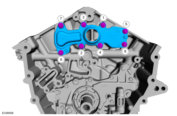
Install the main bearing cap support brace and the new bolts.
Torque:
Stage 1:
20 lb.ft (27 Nm)
Stage 2:
225°
-
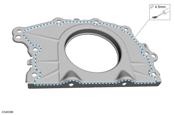
NOTICE:
Failure to use Motorcraft® High Performance Engine RTV
Silicone may cause the engine oil to foam excessively and result in
serious engine damage.
NOTE:
The crankshaft rear seal retainer must be installed and
the bolts tightened within 4 minutes of sealant application.
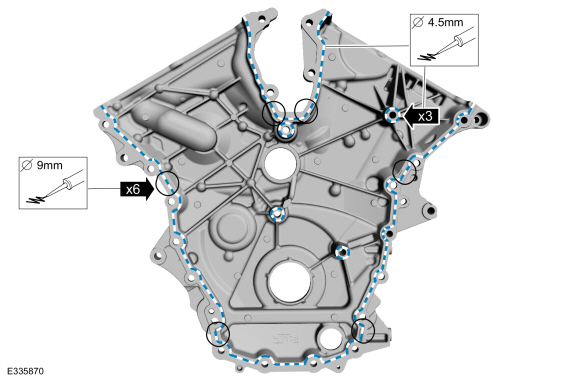
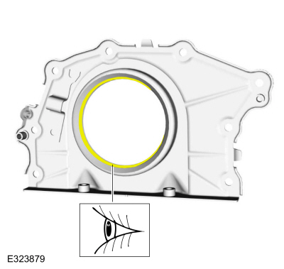
Apply a 4.5 mm (0.18 in) bead of Motorcraft® High
Performance Engine RTV Silicone to the sealing surface of the crankshaft
rear seal retainer.
Material: Motorcraft® High Performance Engine RTV Silicone
/ TA-357
(WSE-M4G323-A6)
-
Lubricate the crankshaft with clean engine oil.
Refer to: Specifications (303-01)
.
-
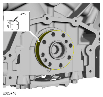
Inspect the rear seal to ensure lip is not inverted.
-
-
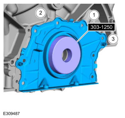
Lubricate the special tool with clean engine oil and install.
Install Special Service Tool: 303-1250
Seal Installer, Rear Main.
-
Remove the special tool.
Remove Suggested Tool: 303-1250
Seal Installer, Rear Main.
-
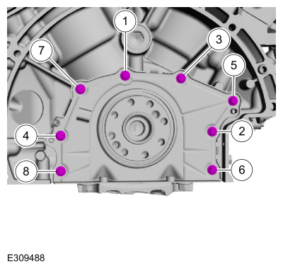
NOTE:
The crankshaft rear seal retainer must be installed and
the bolts tightened within 10 minutes of sealant application.
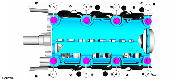
Install the crankshaft rear seal bolts and tighten in sequence shown.
Torque:
Stage 1:
89 lb.in (10 Nm)
Stage 2:
45°
-
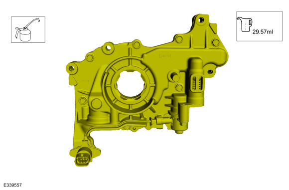
Prime the oil pump. Add 29.57 ml ( 2 tablespoons) of clean
engine oil to the oil pump and rotate the oil pump by hand.
Refer to: Specifications (303-01)
.
-
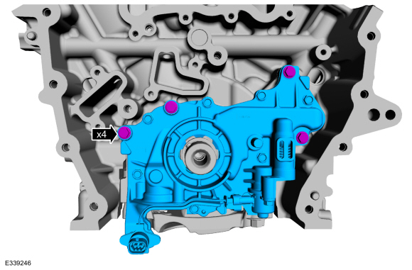
Install the oil pump and the bolts.
Torque:
Stage 1:
89 lb.in (10 Nm)
Stage 2:
45°
-
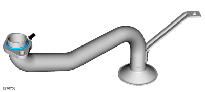
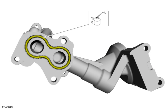
Install a new oil pump screen and pickup tube O-ring seal.
-
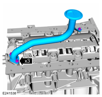
Install the oil pump screen and pickup tube and the bolts.
Torque:
Stage 1:
89 lb.in (10 Nm)
Stage 2:
45°
-
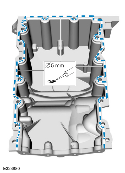
NOTICE:
Failure to use Motorcraft® High Performance Engine RTV
Silicone may cause the engine oil to foam excessively and result in
serious engine damage.
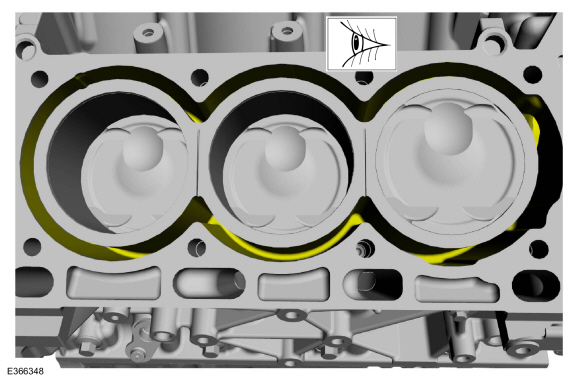
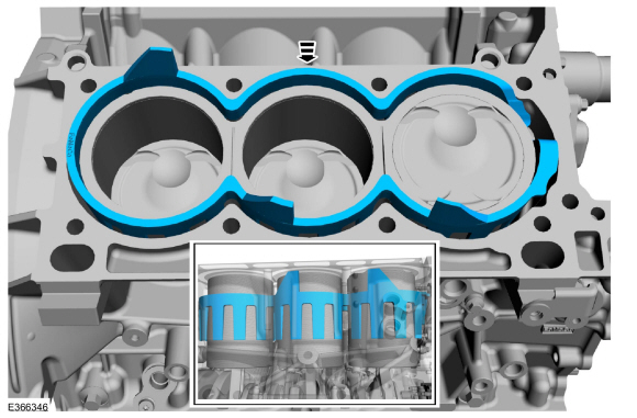
Apply a 5 mm (0.20 in) bead of Motorcraft® High Performance
Engine RTV Silicone to the sealing surface of the oil pan.
-
NOTICE:
Failure to use Motorcraft® High Performance Engine RTV
Silicone may cause the engine oil to foam excessively and result in
serious engine damage.
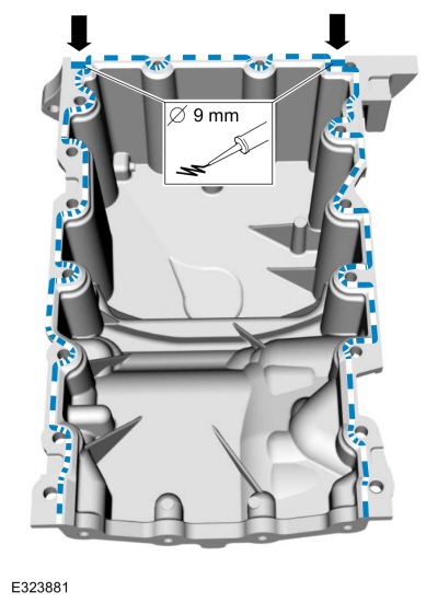
Apply a 9 mm (0.35 in) bead of Motorcraft® High Performance
Engine RTV Silicone to the 2 crankshaft seal retainer plate-to-cylinder
block joint areas on the sealing surface of the oil pan.
-
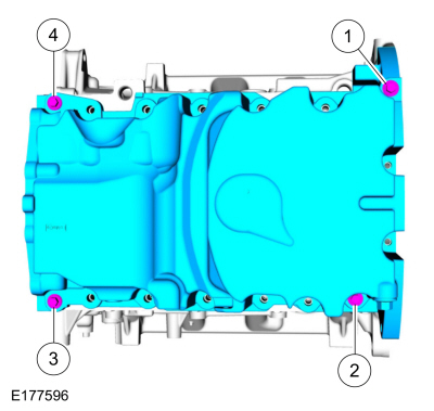
Install the oil pan and bolts.
Torque:
Stage 1:
27 lb.in (3 Nm)
Stage 2:
Loosen::
180°
-
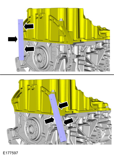
Using a straight edge, align the oil pan flush with the rear of the cylinder block at the 2 areas shown.
Use the General Equipment: Round-Ended Steel Rule
-
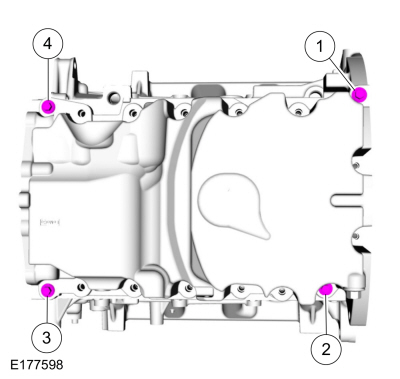
Tighten the bolts in the sequence.
Torque:
27 lb.in (3 Nm)
-
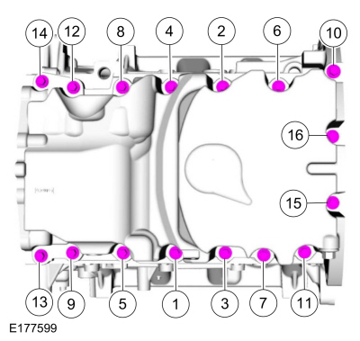
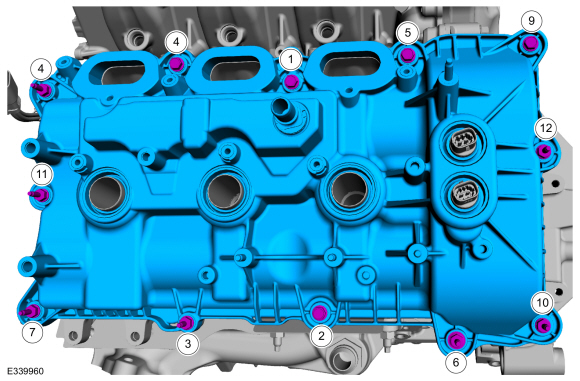
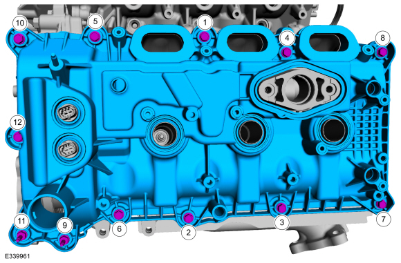
Install the remaining oil pan bolts. Tighten in the sequence shown.
Torque:
Stage 1:
Tighten bolts 1-9 and 11-14 to:
177 lb.in (20 Nm)
Stage 2:
Tighten bolts 1-9 and 11-14 an additional:
45°
Stage 3:
Tighten bolt 10 to:
177 lb.in (20 Nm)
Stage 4:
Tighten bolt 10 an additional:
90°
Stage 5:
Tighten bolts 15 and 16 to:
89 lb.in (10 Nm)
Stage 6:
Tighten bolts 15 and 16 an additional:
45°
-
Install the channel cover plate and the bolts.
Torque:
Stage 1:
89 lb.in (10 Nm)
Stage 2:
45°
-
Install the KS and the bolts.
Torque:
177 lb.in (20 Nm)
-
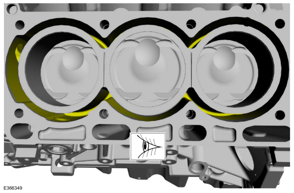
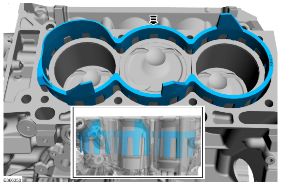
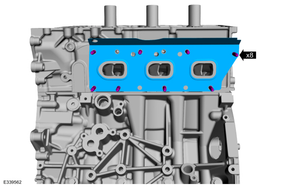
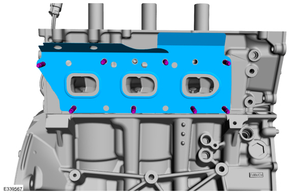
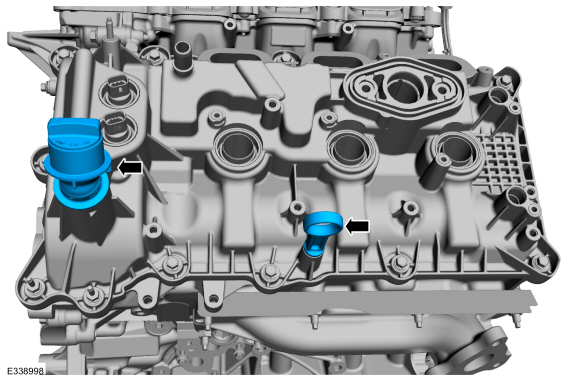
Inspect for any debri before installing the LH water jacket.
-
Install the LH water jacket flush with the bottom of the block.
-
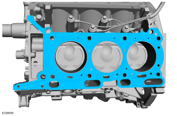
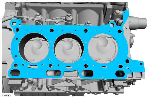
Install the LH cylinder head gasket.
-
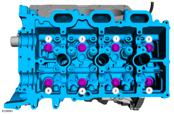
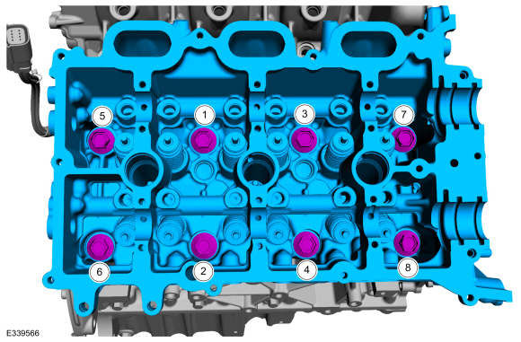
Install the LH cylinder head and the new bolts.
Torque:
Stage 1:
177 lb.in (20 Nm)
Stage 2:
33 lb.ft (45 Nm)
Stage 3:
90°
Stage 4:
90°
Stage 5:
90°
-
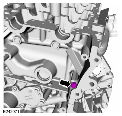
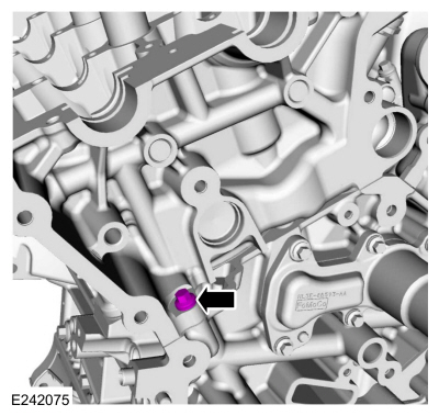
Install the LH M6 bolt.
Torque:
89 lb.in (10 Nm)
-
NOTE:
Install short end of stud into cylinder head assembly.
-
Loosely install the new studs into the LH cylinder head.
-
Tighten the studs in sequence shown.
Torque:
115 lb.in (13 Nm)
-
Install the new exhaust manifold gasket.
-
Install the LH exhaust manifold and the new nuts. Tighten the nuts in sequence shown in 2 stages.
Torque:
Stage 1:
142 lb.in (16 Nm)
Stage 2:
16 lb.ft (22 Nm)
-
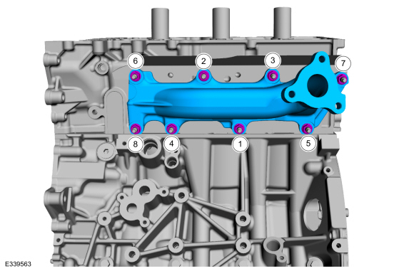
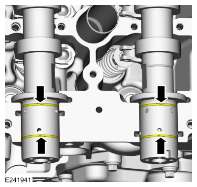
Inspect for any debri before installing the RH water jacket.
-
Install the RH water jacket flush with the bottom of the block.
-
Install the RH cylinder head gasket.
-
Install the RH cylinder head and the new bolts.
Torque:
Stage 1:
177 lb.in (20 Nm)
Stage 2:
33 lb.ft (45 Nm)
Stage 3:
90°
Stage 4:
90°
Stage 5:
90°
-
Install the RH M6 bolt.
Torque:
89 lb.in (10 Nm)
-
NOTE:
Install short end of stud into cylinder head assembly.
-
Loosely install the new studs into the RH cylinder head.
-
Tighten the studs in sequence shown.
Torque:
115 lb.in (13 Nm)
-
Install the new exhaust manifold gasket.
-
Install the RH exhaust manifold and the new nuts. Tighten the nuts in sequence shown in 2 stages.
Torque:
Stage 1:
142 lb.in (16 Nm)
Stage 2:
16 lb.ft (22 Nm)
-
Install the EGR to exhaust manifold connector.
Torque:
125 lb.ft (170 Nm)
-
NOTE:
If the original clipped roller finger follower and
hydraulic lash adjuster assembly is to be reinstalled, they must be
installed in their original locations.
NOTE:
LH shown, RH similar.
-
Lubricate the hydraulic lash adjusters with clean engine oil.
Refer to: Specifications (303-01)
.
-
Install the clipped roller finger followers and hydraulic lash adjuster assemblies.
-
NOTICE:
The crankshaft must remain in the freewheeling position
(crankshaft dowel pin at 9 o'clock) until after the camshafts are
installed. Do not turn the crankshaft until instructed to do so. Failure
to follow this process will result in severe engine damage.
Position the crankshaft dowel pin in the 9 o'clock position.
-
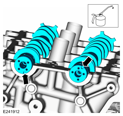
NOTE:
Coat the camshafts with clean engine oil prior to installation.
Lubricate the camshafts with clean engine oil and position the
camshafts onto the RH cylinder head in the neutral position as shown.
Refer to: Specifications (303-01)
.
-
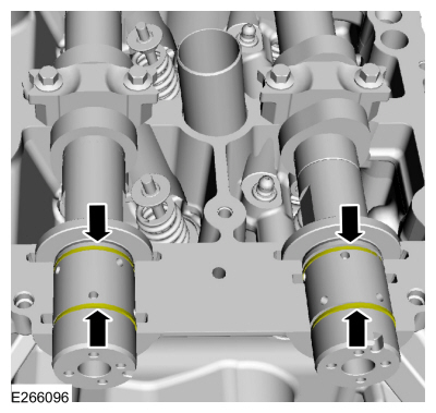
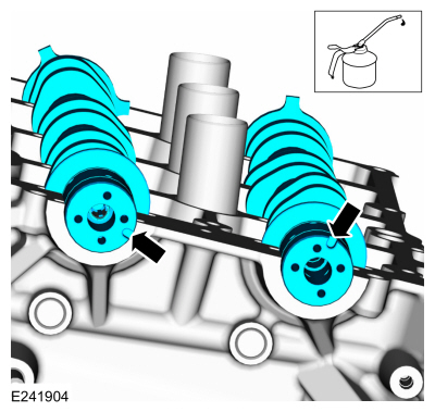
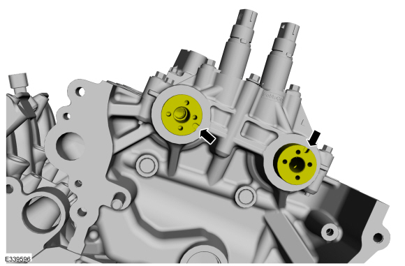
NOTICE:
The camshaft seal gaps must be at the 12 o'clock position or damage to the engine may occur.
Position the RH camshaft seals gaps as shown.
-
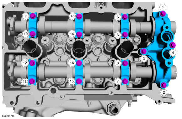
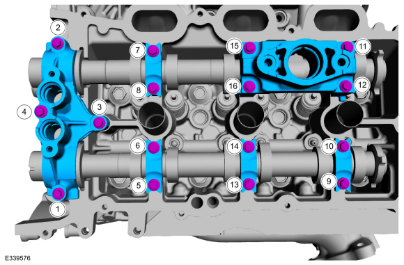
NOTE:
Cylinder head camshaft bearing caps are numbered to verify that they are assembled in their original positions.
-
Install camshaft bearing caps and the bolts.
-
Install camshaft bearing mega caps and the bolts.
Torque:
Stage 1:
1 thru 3:
71 lb.in (8 Nm)
Stage 2:
1 thru 3:
45°
Stage 3:
4:
97 lb.in (11 Nm)
Stage 4:
4:
45°
Stage 5:
5 thru 16:
71 lb.in (8 Nm)
Stage 6:
5 thru 16:
11°
Stage 7:
Loosen 12 and 11:
Loosen: turn(s)
Stage 8:
12 and 11:
71 lb.in (8 Nm)
Stage 9:
12 and 11:
11°
Stage 10:
Loosen 10 and 9:
Loosen: turn(s)
Stage 11:
10 and 9:
71 lb.in (8 Nm)
Stage 12:
10 and 9:
11°
Stage 13:
Loosen 8 and 7:
Loosen: turn(s)
Stage 14:
8 and 7:
71 lb.in (8 Nm)
Stage 15:
8 and 7:
11°
Stage 16:
Loosen 6 and 5:
Loosen: turn(s)
Stage 17:
6 and 5:
71 lb.in (8 Nm)
Stage 18:
6 and 5:
11°
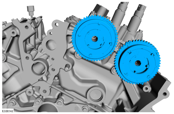
-
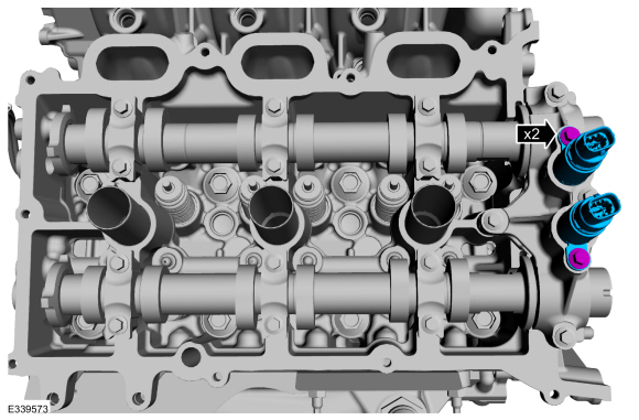
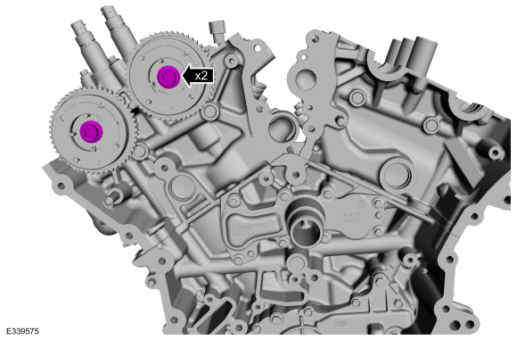
Install the camshaft variable timing assemblies and bolts.
Torque:
97 lb.in (11 Nm)
-
Rotate the RH camshafts to TDC .
-
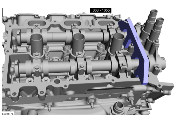
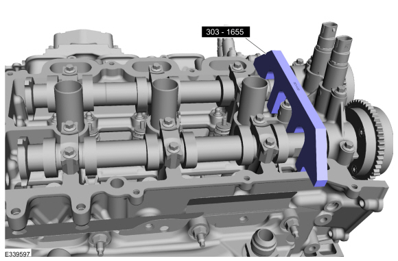
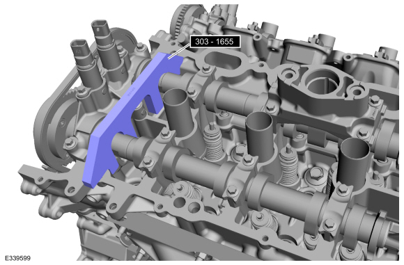
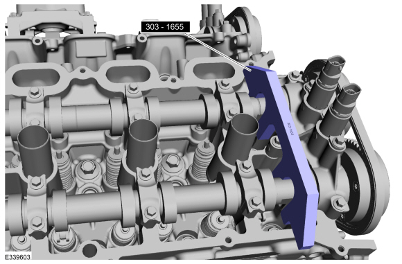
NOTE:
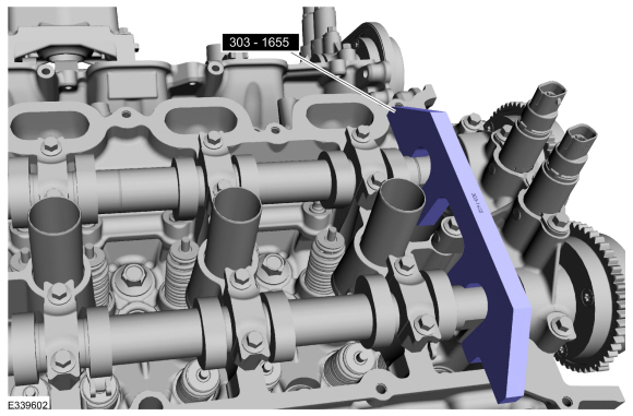
The Camshaft Holding Tool will hold the camshafts in the TDC position.
Install Special Service Tool: 303-1655
Tool, Camshaft Holding.
-
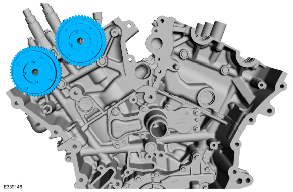
Position the RH
VCT units onto the camshafts.
-
Install the new RH
VCT unit bolts.
Torque:
Stage 1:
30 lb.ft (40 Nm)
Stage 2:
Loosen::
1 turn(s)
Stage 3:
18 lb.ft (25 Nm)
Stage 4:
150°
-
NOTE:
Coat the camshafts with clean engine oil prior to installation.
Lubricate the camshafts with clean engine oil and position the
camshafts onto the LH cylinder head in the neutral position as shown.
Refer to: Specifications (303-01)
.
-
NOTICE:
The camshaft seal gaps must be at the 12 o'clock position or damage to the engine may occur.
Position the LH camshaft seals gaps as shown.
-
NOTE:
Cylinder head camshaft bearing caps are numbered to verify that they are assembled in their original positions.
-
Install camshaft bearing caps and the bolts.
-
Install camshaft bearing mega caps and the bolts.
Torque:
Stage 1:
1 thru 3:
71 lb.in (8 Nm)
Stage 2:
1 thru 3:
45°
Stage 3:
4:
97 lb.in (11 Nm)
Stage 4:
4:
45°
Stage 5:
5 thru 16:
71 lb.in (8 Nm)
Stage 6:
5 thru 16:
11°
Stage 7:
Loosen 12 and 11:
Loosen: turn(s)
Stage 8:
12 and 11:
71 lb.in (8 Nm)
Stage 9:
12 and 11:
11°
Stage 10:
Loosen 10 and 9:
Loosen: turn(s)
Stage 11:
10 and 9:
71 lb.in (8 Nm)
Stage 12:
10 and 9:
11°
Stage 13:
Loosen 8 and 7:
Loosen: turn(s)
Stage 14:
8 and 7:
71 lb.in (8 Nm)
Stage 15:
8 and 7:
11°
Stage 16:
Loosen 6 and 5:
Loosen: turn(s)
Stage 17:
6 and 5:
71 lb.in (8 Nm)
Stage 18:
6 and 5:
11°
-
Install the camshaft variable timing assemblies and bolts.
Torque:
97 lb.in (11 Nm)
-
Rotate the LH camshafts to TDC .
-
Remove Suggested Tool: 303-1655
Tool, Camshaft Holding.
-
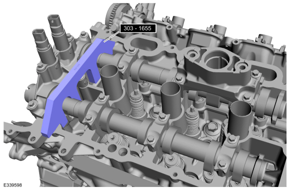
NOTE:
The Camshaft Holding Tool will hold the camshafts in the TDC position.
Install Special Service Tool: 303-1655
Tool, Camshaft Holding.
-
Position the LH
VCT units onto the camshafts.
-
Install the new LH
VCT unit bolts.
Torque:
Stage 1:
30 lb.ft (40 Nm)
Stage 2:
Loosen::
1 turn(s)
Stage 3:
18 lb.ft (25 Nm)
Stage 4:
150°
-
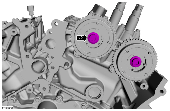
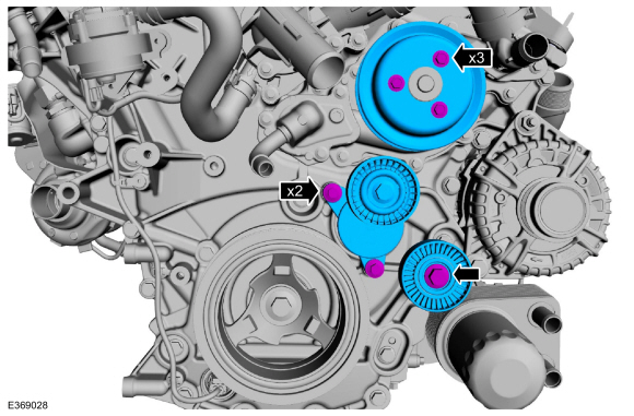
Rotate the crankshaft clockwise 60 degrees to the TDC position (crankshaft dowel pin at 11 o'clock).
-
Install the crankshaft sprocket.
-
NOTE:
The crankshaft sprocket is reversible with a timing mark
on each face. For installation of each timing chain, utilize the timing
mark on the front face of the crankshaft sprocket for chain alignment.
-
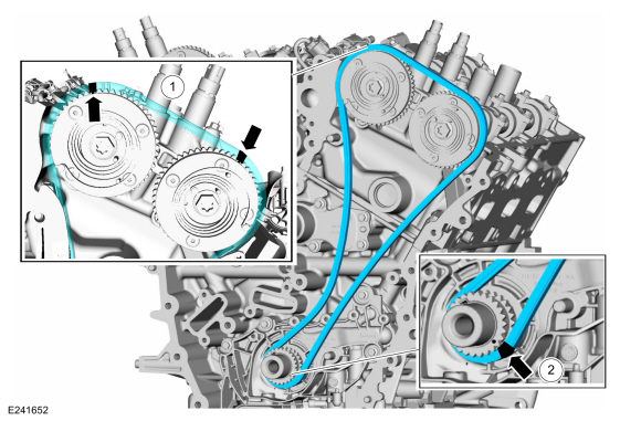
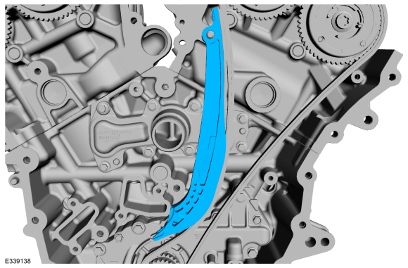
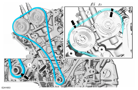
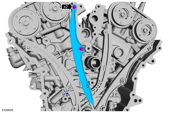
Install the LH timing chain with the single colored links aligned with the timing marks on the VCT units.
-
Install the double colored links so they straddle the timing mark on the crankshaft sprocket.
-
Install the LH timing chain tensioner arm.
-
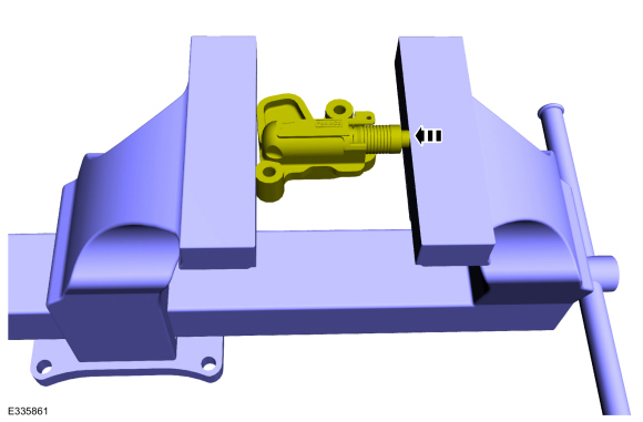
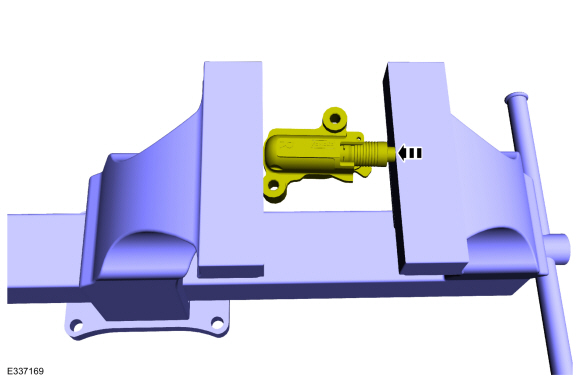
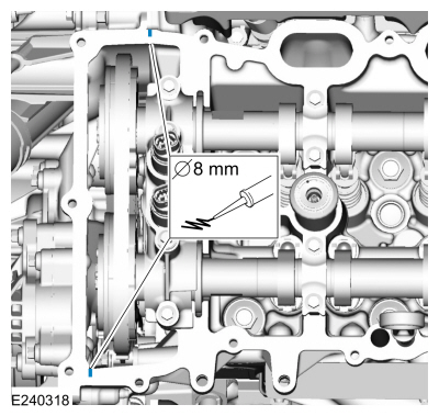
Position the tensioner in a soft-jawed vise.
-
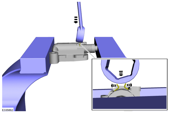
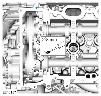
NOTE:
Use of a commercially available tools with a curved
radius in the range of 10 mm - 15 mm is suggested for use in resetting
the ratchet clip. Examples are a 8 mm closed end wrench, 12x12 mm piece
of bar stock, T40 to T50 Torx screwdriver or 3/8 wobble style socket
extender.
Using a commercially available wrench, push down on the ratchet clip so the ratchet clip pushes outward.
-
-
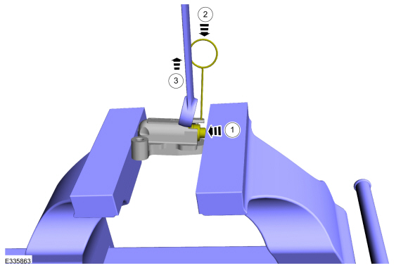
Using the soft-jawed vise, compress the piston to the reset position.
-
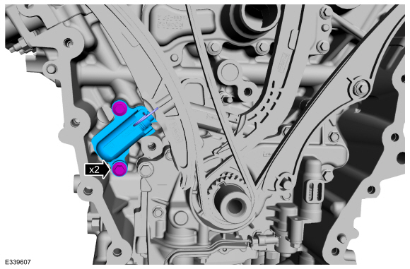
Install a locking pin in the 2 holes of the tensioner body to hold the piston in place.
-
Remove the commercially available tool and the tensioner.
-
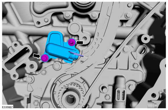
Position the LH timing chain tensioner with the end of the tensioner
correctly engaged to the tensioner arm and install the fasteners.
Torque:
Stage 1:
89 lb.in (10 Nm)
Stage 2:
30°
-
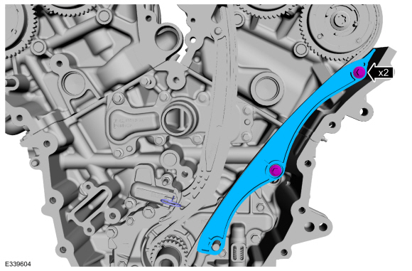
Install the LH timing chain guide and the bolts.
Torque:
Stage 1:
89 lb.in (10 Nm)
Stage 2:
30°
-
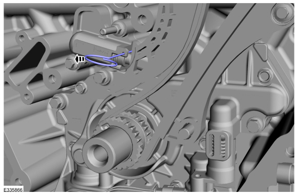
Remove the tensioner pins.
-
Remove Suggested Tool: 303-1655
Tool, Camshaft Holding.
-
Install Special Service Tool: 303-1655
Tool, Camshaft Holding.
-
NOTE:
The crankshaft sprocket is reversible with a timing mark
on each face. For installation of each timing chain, utilize the timing
mark on the front face of the crankshaft sprocket for chain alignment.
-
Install the RH timing chain with the single colored links aligned with the timing marks on the VCT units.
-
Install the double colored links so they straddle the timing mark on the crankshaft sprocket.
-
Install the LH timing chain tensioner arm.
-
Position the tensioner in a soft-jawed vise.
-
NOTE:
Use of a commercially available tools with a curved
radius in the range of 10 mm - 15 mm is suggested for use in resetting
the ratchet clip. Examples are a 8 mm closed end wrench, 12x12 mm piece
of bar stock, T40 to T50 Torx screwdriver or 3/8 wobble style socket
extender.
Using a commercially available wrench, push down on the ratchet clip so the ratchet clip pushes outward.
-
-
Using the soft-jawed vise, compress the piston to the reset position.
-
Install a locking pin in the 2 holes of the tensioner body to hold the piston in place.
-
Remove the commercially available tool and the tensioner.
-
Position theRH timing chain tensioner with the end of the tensioner
correctly engaged to the tensioner arm and install the fasteners.
Torque:
Stage 1:
89 lb.in (10 Nm)
Stage 2:
30°
-
Install the RH timing chain guide and the bolts.
Torque:
Stage 1:
89 lb.in (10 Nm)
Stage 2:
30°
-
Remove the tensioner pins.
-
Remove Special Service Tool: 303-1655
Tool, Camshaft Holding.
-
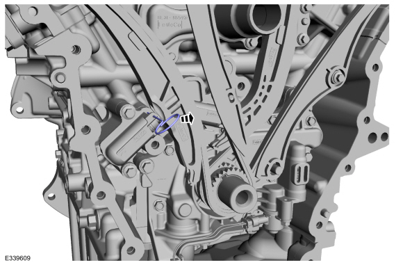
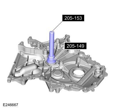
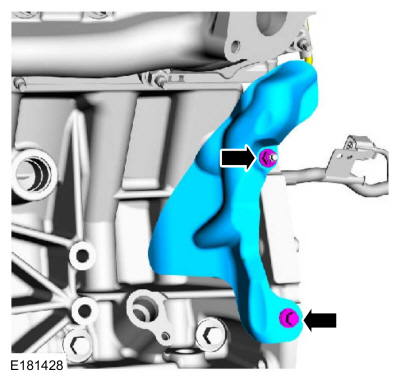
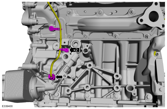
Using the special tools, install the front cover to coolant pipe seal.
Use Special Service Tool: 205-149
(T80T-4000-R)
Installer, Spindle Bearing.
, 205-153
(T80T-4000-W)
Handle.
-
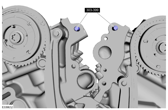
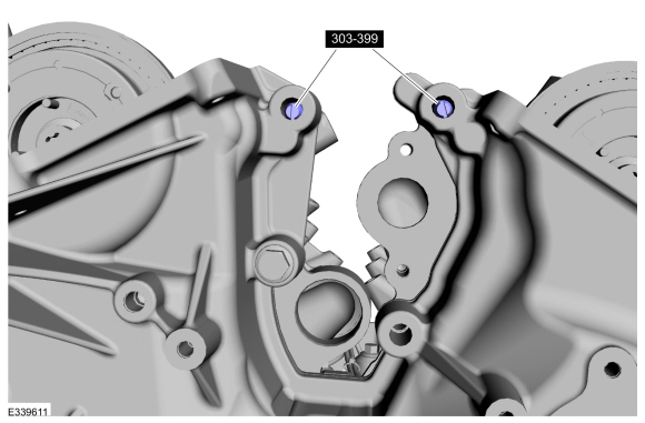
Install Special Service Tool: 307-399
Alignment Pins, Transmission Fluid Pump.
 |
|
-
-
NOTICE:
Failure to use Motorcraft® High Performance Engine
RTV Silicone may cause the engine oil to foam excessively and result in
serious engine damage.
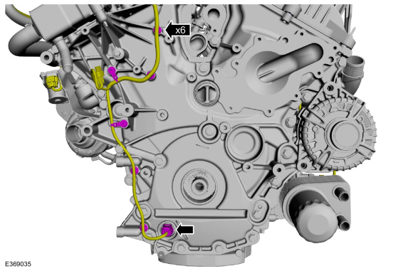
NOTE:
The engine front cover and the 6 bolts must be
installed within 4 minutes of the initial sealant application. The
remainder of the engine front cover bolts must be installed and
tightened within 35 minutes of the initial sealant application. If the
time limits are exceeded, the sealant must be removed, the sealing area
cleaned and sealant reapplied. To clean the sealing area, use silicone
gasket remover and metal surface prep. Failure to follow this procedure
can cause future oil leakage.
Apply a 4.5 mm (0.18 in) bead of Motorcraft® High
Performance Engine RTV Silicone to the engine front cover sealing
surfaces including the inner bolt bosses.
Material: Motorcraft® High Performance Engine RTV Silicone
/ TA-357
(WSE-M4G323-A6)
-
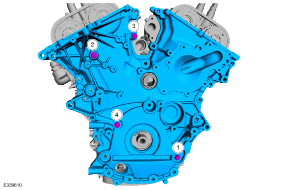
Apply a 9.0 mm (0.35 in) bead of Motorcraft® High
Performance Engine RTV Silicone to the oil pan-to-cylinder block joint
and the cylinder head-to-cylinder block joint areas of the engine front
cover in places as indicated.
Material: Motorcraft® High Performance Engine RTV Silicone
/ TA-357
(WSE-M4G323-A6)
 |
|
-
NOTE:
Make sure the locating dowel pins are seated correctly in the cylinder block.
Install the engine front cover and the bolts.
Torque:
27 lb.in (3 Nm)
-
Remove Special Service Tool: 307-399
Alignment Pins, Transmission Fluid Pump.
-
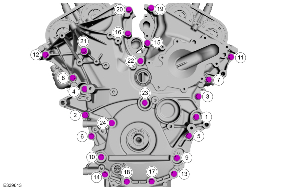
Install the remaining engine front cover bolts.
Torque:
Stage 1:
Tighten bolts 1 thru 24 to:
177 lb.in (20 Nm)
Stage 2:
Tighten bolts 1 thru 24 to:
45°
-
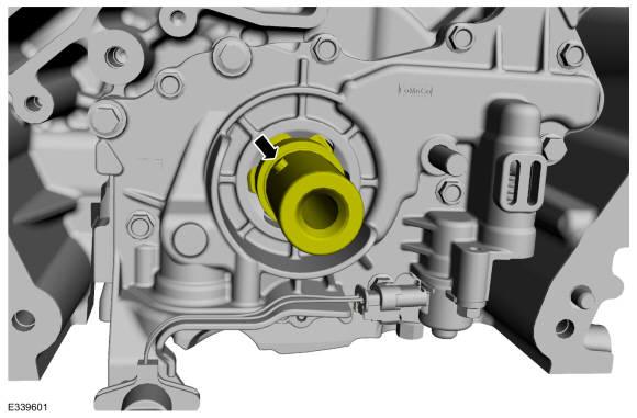
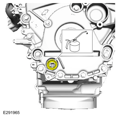
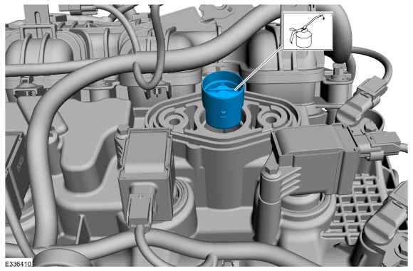
With clean oil, lubricate and position the oil pump electrical connector seal.
Refer to: Specifications (303-01)
.
-
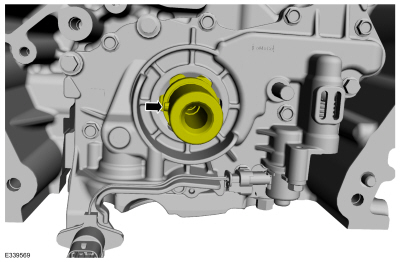
NOTICE:
If the oil pump electrical connector seal is not properly installed, it may result in oil leakage.
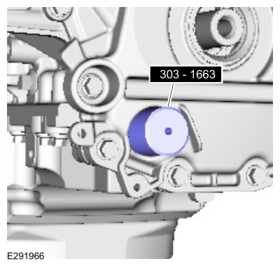
Using the special tool, install the oil pump electrical connector seal.
Install Special Service Tool: 303-1663
Installer, VDOP Seal.
-
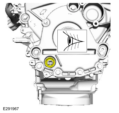
NOTE:
The front surface of the oil pump electrical connector seal will be level with the engine front cover recess.
Inspect the oil pump electrical connector seal for proper installation.
-
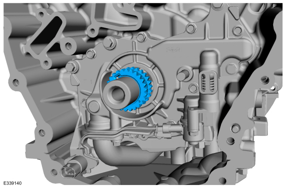
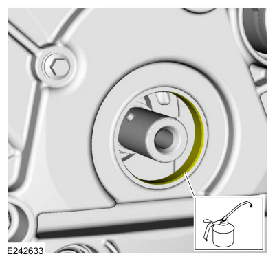
Lubricate the crankshaft front seal bore with clean engine oil.
Refer to: Specifications (303-01)
.
-
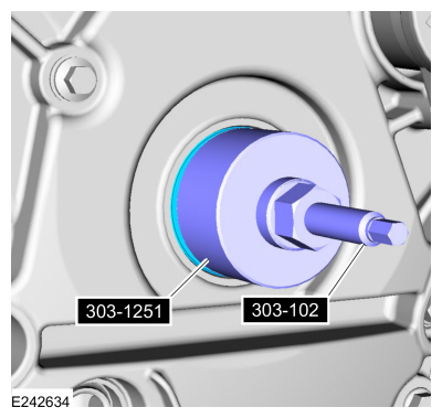
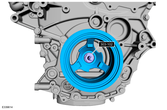
Using the special tools, install the crankshaft front seal.
Use Special Service Tool: 303-102
Installer, Crankshaft Pulley.
, 303-1251
Installer, Front Seal.
-
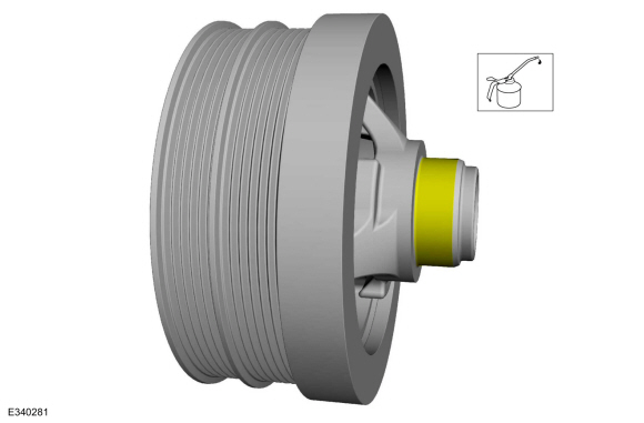
Lubricate the crankshaft pulley with clean engine oil.
Refer to: Specifications (303-01)
.
-
Using the special tool, install the crankshaft pulley.
Use Special Service Tool: 303-102
Installer, Crankshaft Pulley.
-
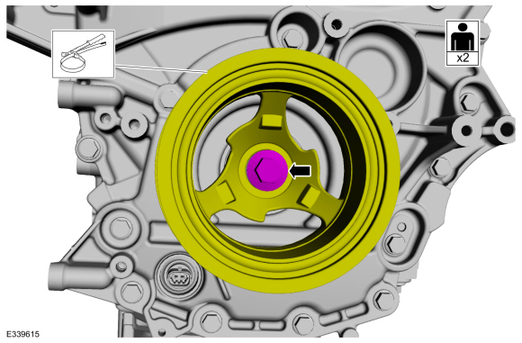
Install the new crankshaft bolt and the washer.
Use the General Equipment: Strap Wrench
Torque:
Stage 1:
37 lb.ft (50 Nm)
Stage 2:
90°
Stage 3:
60°
-
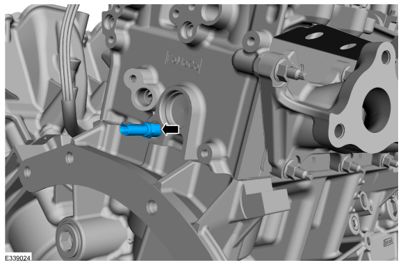
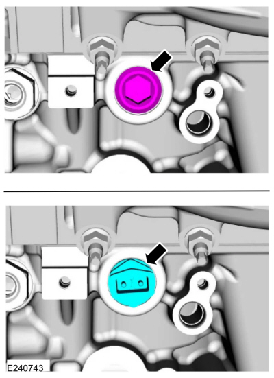
Remove the cylinder head temperature sensor.
-
NOTE:
Apply clean engine oil to the CMP sensor O-ring seals.
Install the CMP sensors and the bolts.
Refer to: Specifications (303-01)
.
Torque:
71 lb.in (8 Nm)
-
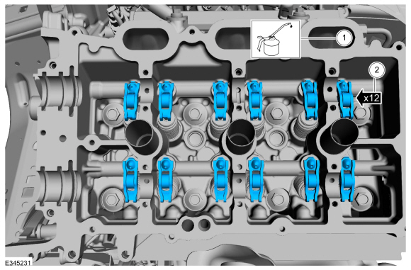
NOTE:
Installation of new seals is only required if damaged seals were removed.
NOTE:
LH shown, RH similar.
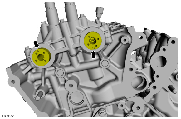
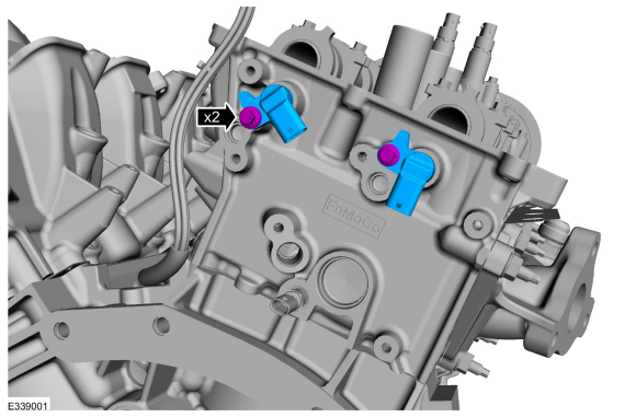
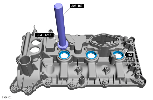
If removed, using the special tools, install the spark plug tube seals.
Use Special Service Tool: 303-1247
VCT Spark Plug Tube Seal Remover and Installer.
, 205-153
(T80T-4000-W)
Handle.
-
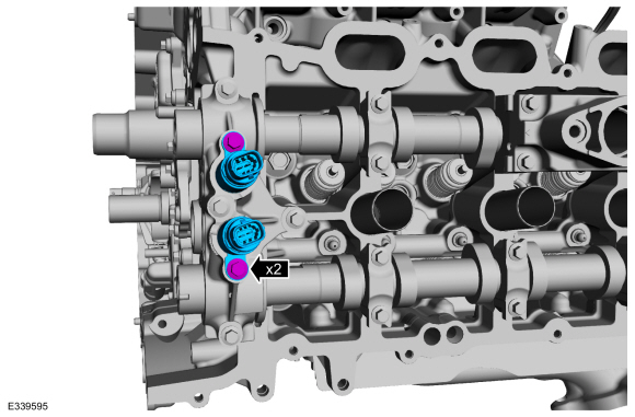
NOTE:
Installation of new seals is only required if damaged seals were removed.
NOTE:
LH shown, RH similar.
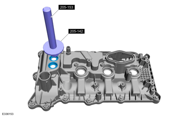
If removed, using the special tools, install the VCT oil control solenoid seals.
Use Special Service Tool: 205-142
(T80T-4000-J)
Installer, Differential Bearing Cone.
, 205-153
(T80T-4000-W)
Handle.
-
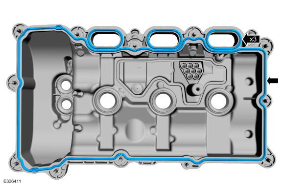
Install a newRH valve cover gaskets.
-
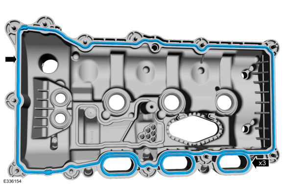
NOTE:
If the valve cover is not installed and the fasteners
tightened within 4 minutes, the sealant must be removed and the sealing
area cleaned. To clean the sealing area, use silicone gasket remover and
metal surface prep. Failure to follow this procedure can cause future
oil leakage.
Apply an 8 mm (0.31 in) bead of Motorcraft® High Performance Engine RTV
Silicone to the engine front cover-to- RH cylinder head joints.
Material: Motorcraft® Metal Surface Prep Wipes
/ ZC-31-B
Material: Motorcraft® Silicone Gasket Remover
/ ZC-30-A, AZC-30-C
Material: Motorcraft® High Performance Engine RTV Silicone
/ TA-357
(WSE-M4G323-A6)
-
Install the RH valve cover and the fasteners.
Torque:
89 lb.in (10 Nm)
-
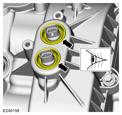
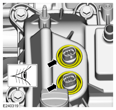
Make sure the VCT seals in the valve cover are below the top of the VCT
oil control solenoid electrical connector or the VCT seal may leak oil.
-
Install a new LH valve cover gaskets.
-
NOTE:
If the valve cover is not installed and the fasteners
tightened within 4 minutes, the sealant must be removed and the sealing
area cleaned. To clean the sealing area, use silicone gasket remover and
metal surface prep. Failure to follow this procedure can cause future
oil leakage.
Apply an 8 mm (0.31 in) bead of Motorcraft® High Performance Engine RTV
Silicone to the engine front cover-to- LH cylinder head joints.
Material: Motorcraft® Metal Surface Prep Wipes
/ ZC-31-B
Material: Motorcraft® Silicone Gasket Remover
/ ZC-30-A, AZC-30-C
Material: Motorcraft® High Performance Engine RTV Silicone
/ TA-357
(WSE-M4G323-A6)
-
Install the LH valve cover and the fasteners.
Torque:
89 lb.in (10 Nm)
-
Make sure the VCT seals in the valve cover are below the top of the VCT
oil control solenoid electrical connector or the VCT seal may leak oil.
-
Install the oil fill pipe and the oil level indicator.
-
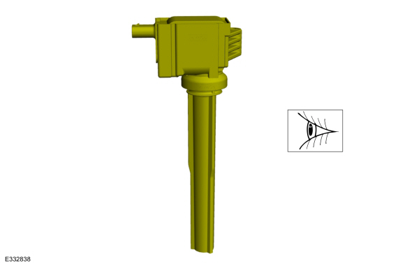
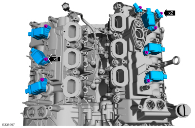
Inspect the ignition coil-on-plugs. Replace any damaged
ignition coil-on-plugs. Replace any of the ignition coil-on-plug boots
with cracks, rips or tears.
-
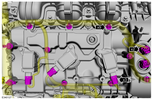
-
Install all of the ignition coil-on-plugs and the bolts.
Torque:
Stage 1:
62 lb.in (7 Nm)
Stage 2:
50 °
-
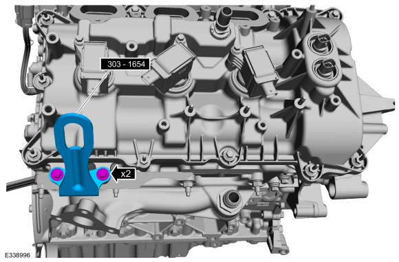
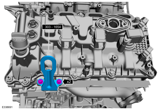
Install Special Service Tool: 303-1654
Lift Eyes.
-
Install Special Service Tool: 303-1654
Lift Eyes.
-
-
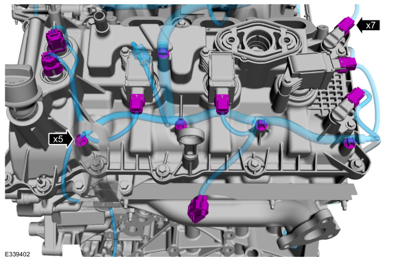
Attach the wire harness retainers.
-
Connect the ignition coil-on-plug electrical connectors.
-
Connect the CMP sensor electrical connectors.
-
Connect the VCT oil control solenoid electrical connectors.
-
Install the ground wire and stud.
-
-
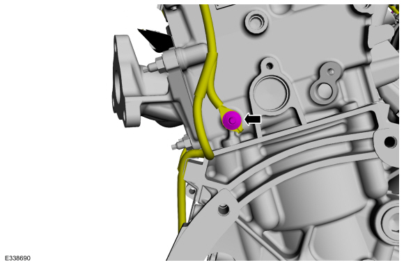
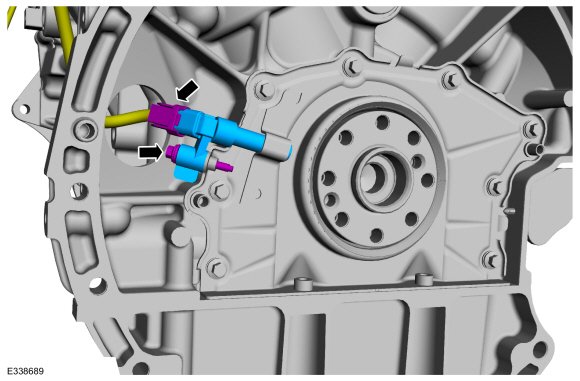
Install the CKP sensor and bolt.
Torque:
62 lb.in (7 Nm)
-
Connect the CKP sensor electrical connector.
-
-
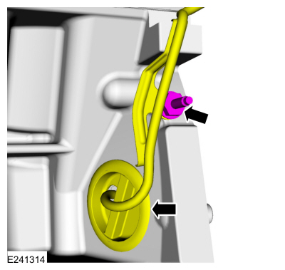
Attach the wiring harness grommet to the cylinder block.
-
Install the studbolt.
Torque:
89 lb.in (10 Nm)
-
Install the nut, bolt and the heat shield.
Torque:
89 lb.in (10 Nm)
-
Install the heat shield, bolt and studbolt.
Torque:
89 lb.in (10 Nm)
-
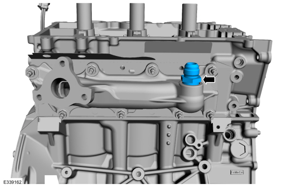
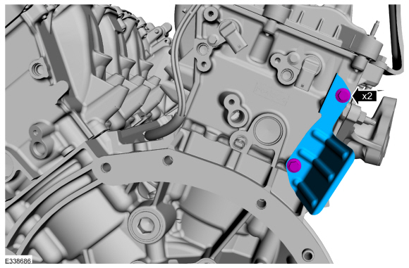
Install the RH block coolant drain plug.
Torque:
Stage 1:
142 lb.in (16 Nm)
Stage 2:
180°
-
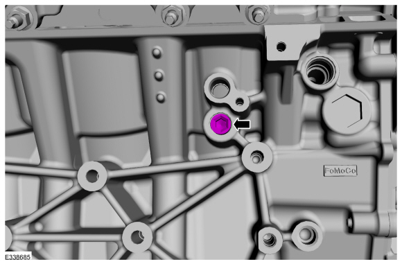
Install the LH block drain plug or block heater.
Torque:
30 lb.ft (40 Nm)
-
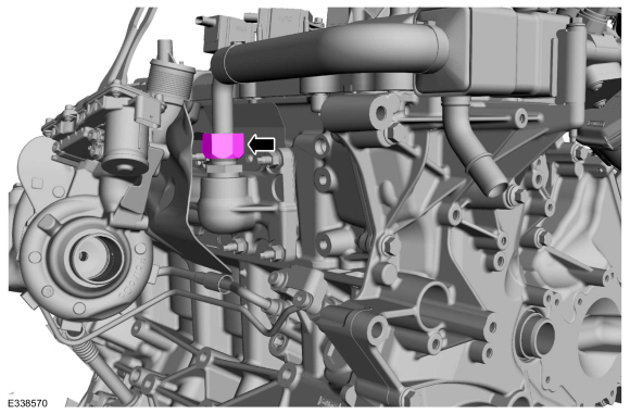
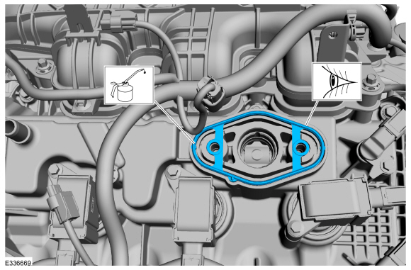
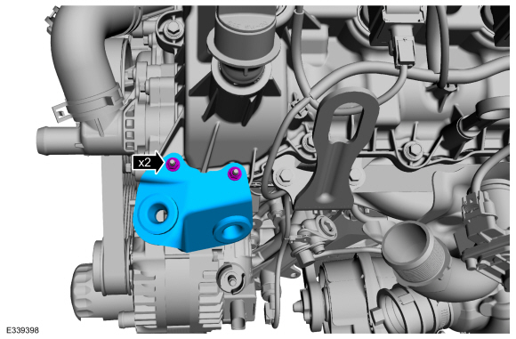
If discarded install a new gasket and lubricate with clean oil.
Refer to: Specifications (303-01)
.
-
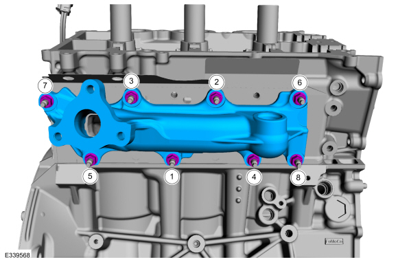
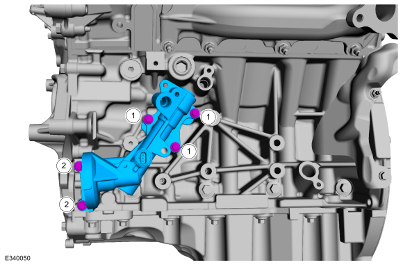
NOTE:
Tighten the upper bolts first.
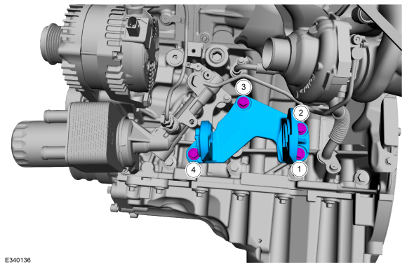
Install the oil filter adapter and the bolts.
Torque:
Stage 1:
Bolts 1:
89 lb.in (10 Nm)
Stage 2:
Bolts 1:
45°
Stage 3:
Bolts 2:
89 lb.in (10 Nm)
Stage 4:
Bolts 2:
45°
-
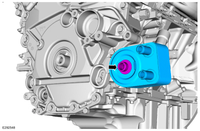
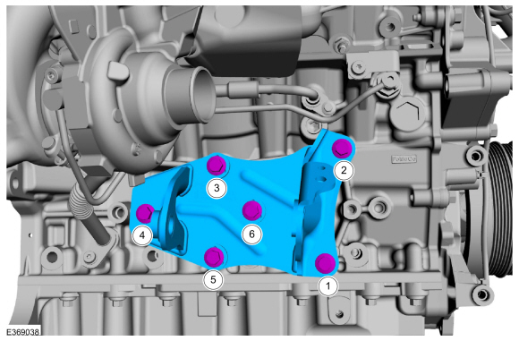
NOTICE:
A new oil cooler must be installed or severe damage to the engine can occur.
Install the new oil cooler and the bolt.
Torque:
Stage 1:
43 lb.ft (58 Nm)
Stage 2:
9 °
-
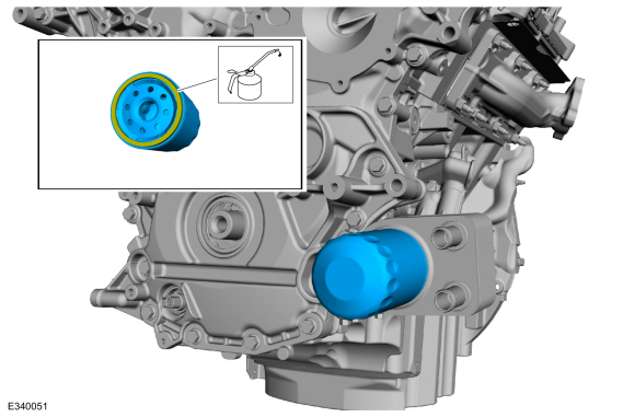
Lubricate the oil filter seal with clean oil and install the new oil filter.
Refer to: Specifications (303-01)
.
Torque:
Stage 1:
44 lb.in (5 Nm)
Stage 2:
180 °
-
Connect the EOP sensor electrical connector and the wire harness retainer.
-
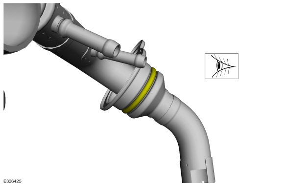
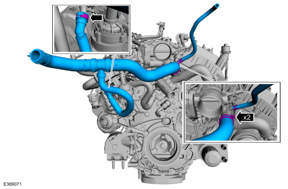
Install the new TC gasket
by pressing the gasket into the turbocharger flange groove evenly until
at least 50% of the gasket is within the groove.
-
If a TC cooling tube was separated, then replace the separated TC
cooling tube rubber gaskets. After installing the rubber gasket,
lubricate with clean engine coolant.
-
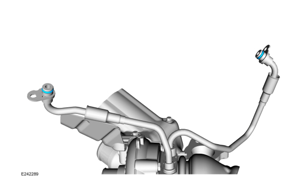
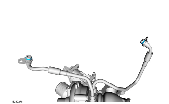
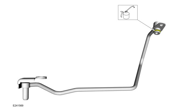
Install the new TC coolant supply tube and the new TC coolant return
tube O-ring seals. Lubricate the new O-ring seal with clean engine
coolant.
-
NOTICE:
Carefully use a nylon brush to remove the old O-ring
residue and use brake cleaner to rinse the O-ring residue out of the
turbocharger tube to engine O-ring bores. Inspect the area for deep
scratches and gouges. DO-NOT USE A METAL BRUSH; DAMAGE TO SEALING AREA
WILL RESULT IN LEAKS.
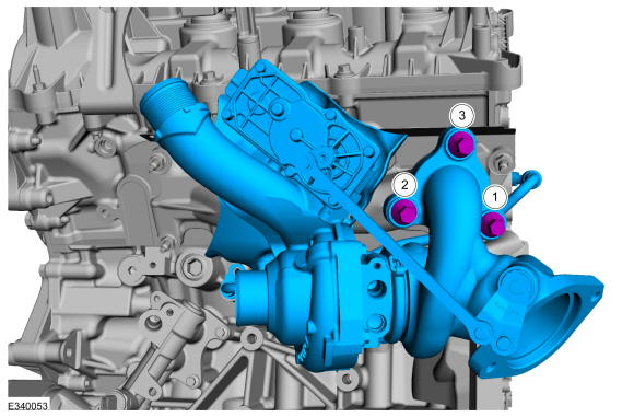
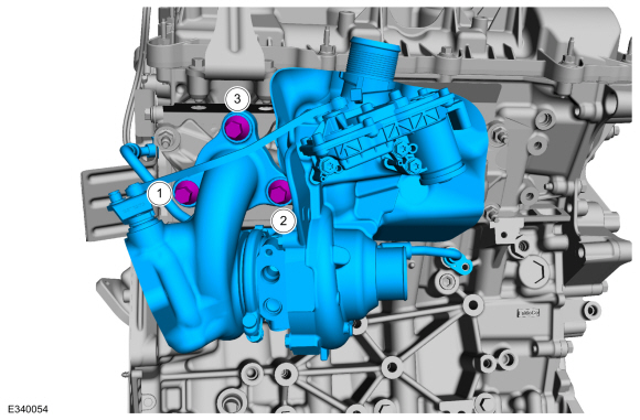
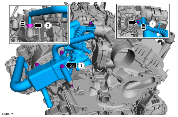
NOTE:
Install the coolant tubes with the TC .
Install the LH
TC and tighten the new retainers in the following 2 stages.
Torque:
Stage 1:
Tighten 1-3 in the sequence shown to :
24 lb.ft (32 Nm)
Stage 2:
Re-tighten 1 to :
24 lb.ft (32 Nm)
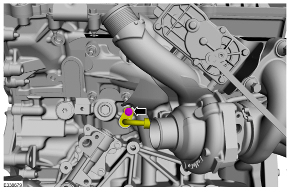
-
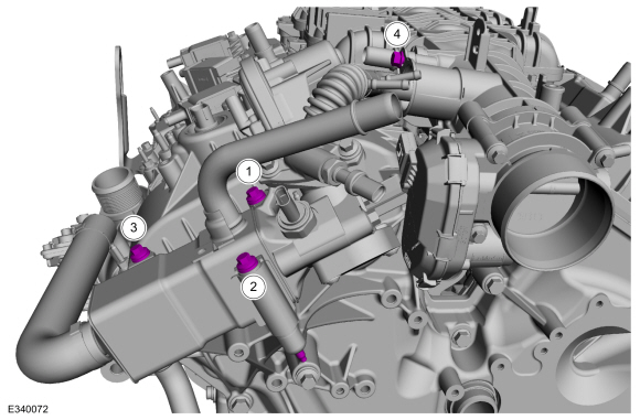
Install the LH
TC coolant supply tube and bolt.
Torque:
Stage 1:
89 lb.in (10 Nm)
Stage 2:
30°
-
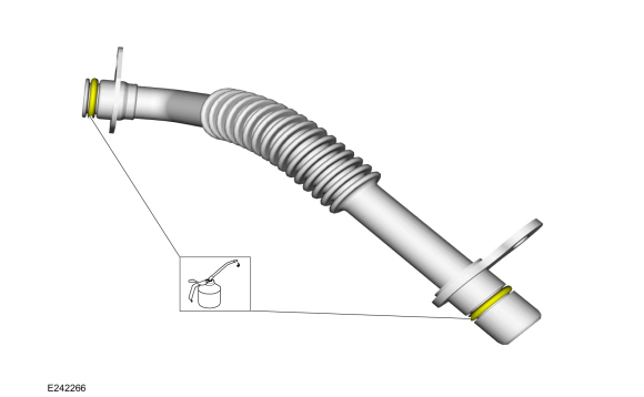
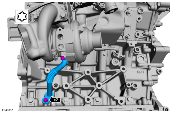
Lubricate the new LH
TC oil return tube O-ring seals with clean engine oil.
-
NOTICE:
Carefully use a nylon brush to remove the old O-ring
residue and use brake cleaner to rinse the O-ring residue out of the
turbocharger and engine O-ring bores. Inspect the area for deep
scratches and gouges. DO-NOT USE A METAL BRUSH; DAMAGE TO SEALING AREA
WILL RESULT IN LEAKS.
NOTE:
Fully seat the TC oil
return tube into the turbocharger and engine bore holes flush to 2.5 mm
off the mounting surface prior to fastener rundown.
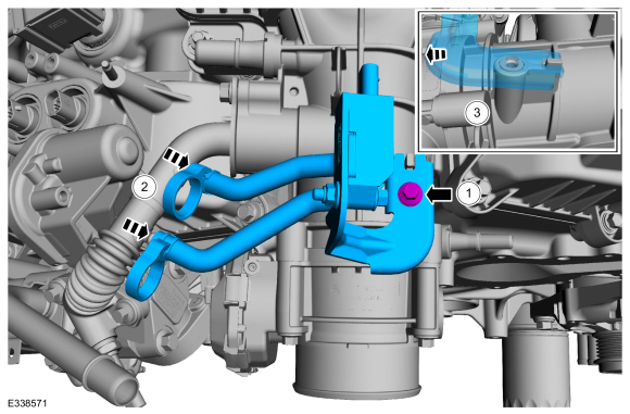
Install the new LH
TC oil return tube, then install and tighten the TC oil return tube bolts.
Torque:
Stage 1:
89 lb.in (10 Nm)
Stage 2:
30°
-
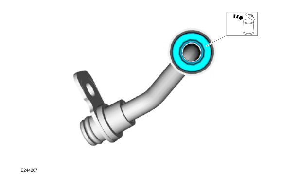
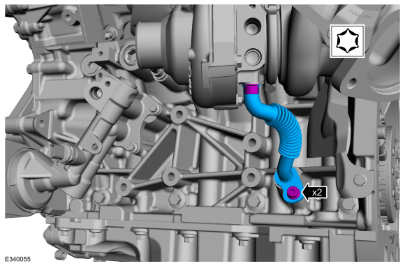
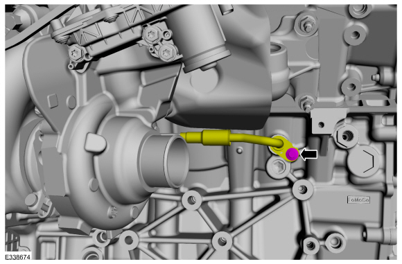
Lubricate the new LH
TC oil supply tube O-ring seal with clean engine oil.
-
NOTICE:
Use brake cleaner on a lint free rag to remove the O-ring residue out of the TC tube to TC
turbocharger O-ring bore. Inspect the area for deep scratches and
gouges. DO-NOT USE ANY BRUSHES; DAMAGE TO SEALING AREA WILL RESULT IN
LEAKS AND POSSIBLE INTERNAL TURBO BEARING DAMAGE.
NOTE:
Fully seat the TC oil supply tube into the TC bore hole flush to 2.5 mm off the mounting surface prior to fastener rundown.
The TC oil supply tube must be installed into the TC fitting along
the centerline. The assembly is complete when the TC oil supply tube end
bottoms out in the TC brackets bottom on mating surfaces and the M6
fastener has been fully installed.
Install the new LH
TC oil supply tube, then install and tighten the TC oil supply tube
bolts.
Material: Motorcraft® Metal Brake Parts Cleaner
/ PM-4-A, PM-4-B, APM-4-C
-
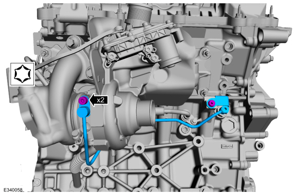
Install the LH
TC coolant return tube and the bolt.
Torque:
Stage 1:
89 lb.in (10 Nm)
Stage 2:
30°
-
Connect LH
TC electrical connector.
-
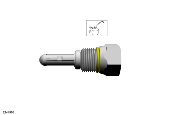
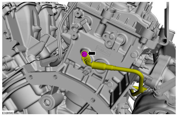
Lubricate the new TC fitting and oil filter assembly O-ring seal with clean engine oil.
Refer to: Specifications (303-01)
.
-
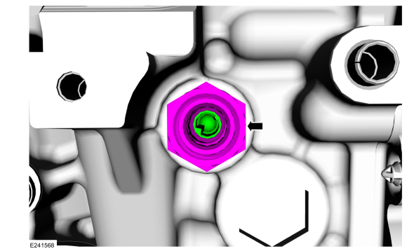
Install and tighten the new RH
TC fitting and oil filter assembly into the engine block.
Torque:
24 lb.ft (32 Nm)
-
Install the new TC gasket
by pressing the gasket into the turbocharger flange groove evenly until
at least 50% of the gasket is within the groove.
-
If a TC cooling tube was separated, then replace the separated TC
cooling tube rubber gaskets. After installing the rubber gasket,
lubricate with clean engine coolant.
-
Install the new TC coolant supply tube and the new TC coolant return
tube O-ring seals. Lubricate the new O-ring seal with clean engine
coolant.
Refer to: Specifications (303-01)
.
-
NOTICE:
Carefully use a nylon brush to remove the old O-ring
residue and use brake cleaner to rinse the O-ring residue out of the TC
tube to engine O-ring bores. Inspect the area for deep scratches and
gouges. DO-NOT USE A METAL BRUSH; DAMAGE TO SEALING AREA WILL RESULT IN
LEAKS.
NOTE:
Install the coolant tubes with the TC .
Install the RH
TC and tighten the new retainers in the following 2 stages.
Torque:
Stage 1:
Tighten 1-3 in the sequence shown to :
24 lb.ft (32 Nm)
Stage 2:
Re-tighten 1 to :
24 lb.ft (32 Nm)
-
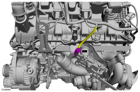
Install the RH
TC coolant supply tube and bolt.
Torque:
Stage 1:
89 lb.in (10 Nm)
Stage 2:
30°
-
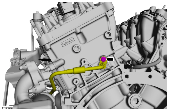
Lubricate the new RH
TC oil return tube O-ring seals with clean engine oil.
Refer to: Specifications (303-01)
.
-
NOTICE:
Carefully use a nylon brush to remove the old O-ring
residue and use brake cleaner to rinse the O-ring residue out of the
turbocharger and engine O-ring bores. Inspect the area for deep
scratches and gouges. DO-NOT USE A METAL BRUSH; DAMAGE TO SEALING AREA
WILL RESULT IN LEAKS.
NOTE:
Fully seat the TC oil
return tube into the turbocharger and engine bore holes flush to 2.5 mm
off the mounting surface prior to fastener rundown.
Install the new RH
TC oil return tube, then install and tighten the TC oil return tube bolts.
Torque:
Stage 1:
89 lb.in (10 Nm)
Stage 2:
30°
-
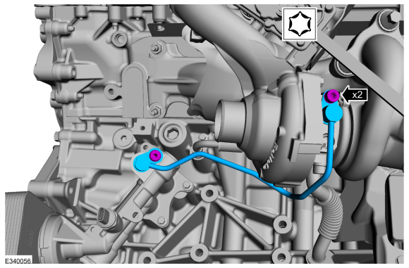
Lubricate the new RH
TC oil supply tube O-ring seal with clean engine oil.
Refer to: Specifications (303-01)
.
-
NOTICE:
Use brake cleaner on a lint free rag to remove the O-ring residue out of the TC tube to TC
turbocharger O-ring bore. Inspect the area for deep scratches and
gouges. DO-NOT USE ANY BRUSHES; DAMAGE TO SEALING AREA WILL RESULT IN
LEAKS AND POSSIBLE INTERNAL TURBO BEARING DAMAGE.
NOTE:
Fully seat the TC oil supply tube into the TC bore hole flush to 2.5 mm off the mounting surface prior to fastener rundown.
The TC oil supply tube must be installed into the TC fitting along
the centerline. The assembly is complete when the TC oil supply tube end
bottoms out in the TC brackets bottom on mating surfaces and the M6
fastener has been fully installed.
Install the new RH
TC oil supply tube, then install and tighten the TC oil supply tube
bolts.
Material: Motorcraft® Metal Brake Parts Cleaner
/ PM-4-A, PM-4-B, APM-4-C
Torque:
Stage 1:
89 lb.in (10 Nm)
Stage 2:
30°
-
Install the RH
TC coolant return tube and the bolt.
Torque:
Stage 1:
89 lb.in (10 Nm)
Stage 2:
30°
-
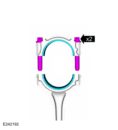
NOTICE:
Do not lubricate the new lower Teflon® fuel injector seals.
-
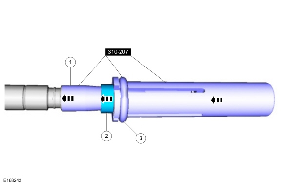
Install the Arbor on the fuel injector tips.
Use Special Service Tool: 310-207
Installer, Fuel Injector Seal Assembly.
-
NOTICE:
Once the Teflon® seal is installed on the Teflon®
Seal Guide, it should immediately be installed onto the fuel injector to
avoid excessive expansion of the Teflon® seal.
NOTE:
Make sure that new lower fuel injector Teflon® seals are installed.
Install the new Teflon® seals onto the Arbor, using the
Pusher Tool (part of the Fuel Injector Seal Installer), slide the
Teflon® seals along the Arbor.
-
Using the Pusher Tool, slide the Teflon® seals off of
the Teflon® Seal Guide and into the groove on the fuel injectors.
Use Special Service Tool: 310-207
Installer, Fuel Injector Seal Assembly.
 |
|
-
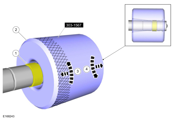
NOTICE:
Install the fuel injectors into the cylinder head within
15 minutes of sizing the seals due to Teflon® seal expansion.
NOTE:
Make sure the Teflon® seal is fully seated in the groove on the fuel injector before sizing the Teflon® seal.
-
Some Teflon® seal massaging with your fingers before the
Teflon® seal sizer tool is installed will aid in installing the Teflon®
seal sizer tool.
-
Position the Teflon® Seal Sizer tool with the larger
opening towards the Teflon® seal. Push while turning the Teflon® Seal
Sizer tool 180 degrees.
Use Special Service Tool: 303-1567
Sizer, Teflon Seal.
-
Once the Teflon® Seal Sizer tool is installed, check and
make sure the Teflon® seal is in the sizing portion of the Teflon® Seal
Sizer tool. After one minute, turn the Teflon® Seal Sizer tool back 180
degrees and remove.
-
After one minute, turn the Teflon® seal sizer tool back 180 degrees and remove.
 |
|
-
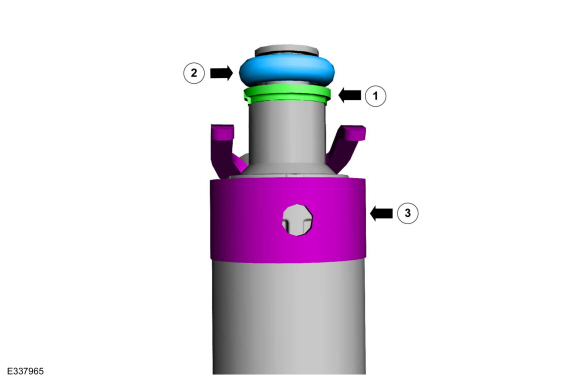
-
NOTICE:
The large diameter step of the backup ring must go
up towards the new O-ring seal. Improperly installed backup rings may
cause the fuel system to leak.
Install the fuel injector backup ring.
-
NOTICE:
Use fuel injector O-ring seals that are made of
special fuel-resistant material. The use of ordinary O-ring seals may
cause the fuel system to leak. Do not reuse the O-ring seals.
NOTE:
Do not lubricate the new lower Teflon® fuel injector seals.
Install the new fuel injector O-ring seals. Lubricate the new fuel injector O-ring seals with clean engine oil.
Refer to: Specifications (303-01)
.
-
Install the new the fuel injector retaining clip.
-
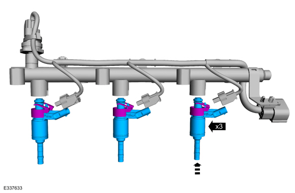
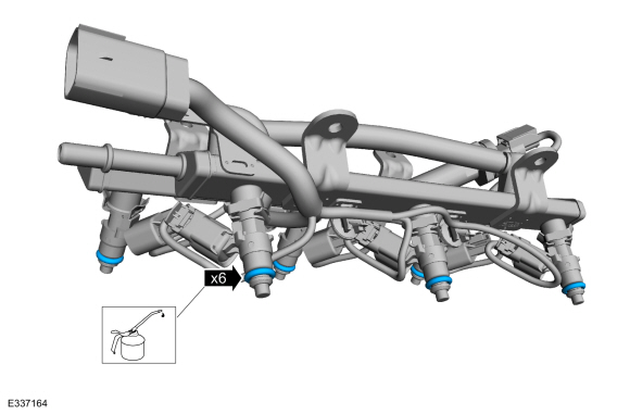
NOTICE:
The anti-rotation finger of the fuel injector must slip into the groove of the fuel rail cup.
Install the fuel injectors into the fuel rail.
-
Connect the fuel injector electrical connectors.
-
NOTE:
Do not lubricate the new lower Teflon® fuel injector seals.
NOTE:
Make sure that new fuel rail mounting bolts are installed.
NOTE:
Push down on the fuel rail above the injectors.
-
Install the fuel injectors and direct injection fuel
rail assembly into the cylinder head. Tighten the bolts in sequence
shown in 2 stages.
Torque:
Stage 1:
89 lb.in (10 Nm)
Stage 2:
45°
 |
|
-
NOTICE:
Do not lubricate the new lower Teflon® fuel injector seals.
-
Install the Arbor on the fuel injector tips
Use Special Service Tool: 310-207
Installer, Fuel Injector Seal Assembly.
-
NOTICE:
Once the Teflon® seal is installed on the Teflon®
Seal Guide, it should immediately be installed onto the fuel injector to
avoid excessive expansion of the Teflon® seal.
NOTE:
Make sure that new lower fuel injector Teflon® seals are installed.
Install the new Teflon® seals onto the Arbor, using the
Pusher Tool (part of the Fuel Injector Seal Installer), slide the
Teflon® seals along the Arbor.
-
Using the Pusher Tool, slide the Teflon® seals off of
the Teflon® Seal Guide and into the groove on the fuel injectors.
Use Special Service Tool: 310-207
Installer, Fuel Injector Seal Assembly.
|
|
-
NOTICE:
Install the fuel injectors into the cylinder head within
15 minutes of sizing the seals due to Teflon® seal expansion.
NOTE:
Make sure the Teflon® seal is fully seated in the groove on the fuel injector before sizing the Teflon® seal.
-
Some Teflon® seal massaging with your fingers before the
Teflon® seal sizer tool is installed will aid in installing the Teflon®
seal sizer tool.
-
Position the Teflon® Seal Sizer tool with the larger
opening towards the Teflon® seal. Push while turning the Teflon® Seal
Sizer tool 180 degrees.
Use Special Service Tool: 303-1567
Sizer, Teflon Seal.
-
Once the Teflon® Seal Sizer tool is installed, check and
make sure the Teflon® seal is in the sizing portion of the Teflon® Seal
Sizer tool. After one minute, turn the Teflon® Seal Sizer tool back 180
degrees and remove.
-
After one minute, turn the Teflon® seal sizer tool back 180 degrees and remove.
|
|
-
-
NOTICE:
The large diameter step of the backup ring must go
up towards the new O-ring seal. Improperly installed backup rings may
cause the fuel system to leak.
Install the fuel injector backup ring.
-
NOTICE:
Use fuel injector O-ring seals that are made of
special fuel-resistant material. The use of ordinary O-ring seals may
cause the fuel system to leak. Do not reuse the O-ring seals.
NOTE:
Do not lubricate the new lower Teflon® fuel injector seals.
Install the new fuel injector O-ring seals. Lubricate the new fuel injector O-ring seals with clean engine oil.
Refer to: Specifications (303-01)
.
-
Install the new the fuel injector retaining clip.
-
NOTICE:
The anti-rotation finger of the fuel injector must slip into the groove of the fuel rail cup.
Install the fuel injectors into the fuel rail.
-
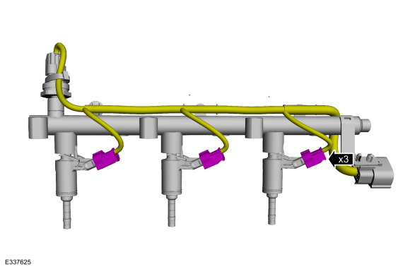
Connect the fuel injector electrical connectors.
-
NOTE:
Do not lubricate the new lower Teflon® fuel injector seals.
NOTE:
Make sure that new fuel rail mounting bolts are installed.
NOTE:
Push down on the fuel rail above the injectors.
-
Install the fuel injectors and direct injection fuel
rail assembly into the cylinder head. Tighten the bolts in sequence
shown in 2 stages.
Torque:
Stage 1:
89 lb.in (10 Nm)
Stage 2:
45°
-
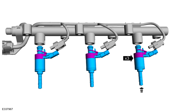
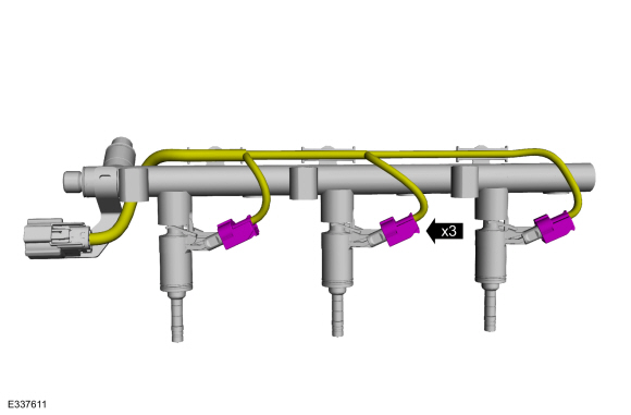
Connect the fuel injector electrical connectors.
-
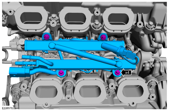
Install the new fuel injector O-ring seals onto the fuel
injectors. Lubricate the new fuel injector O-ring seals with clean
engine oil.
Refer to: Specifications (303-01)
.
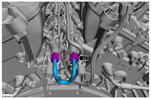
-
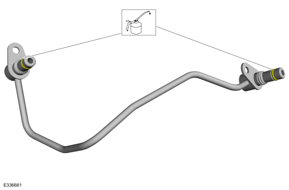
Install the new fuel rail-to-fuel rail high-pressure fuel tube.
-
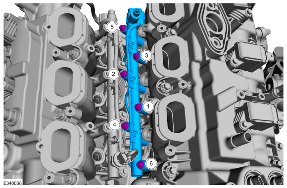
Install the fuel manifold and bolts.
Torque:
Stage 1:
89 lb.in (10 Nm)
Stage 2:
45°
-
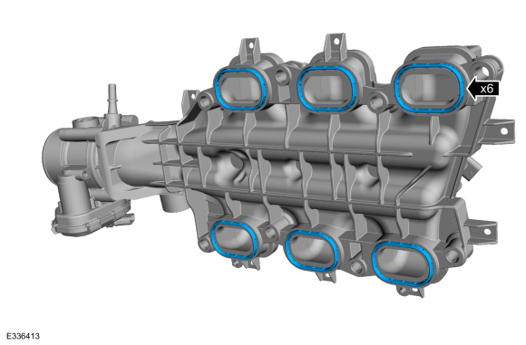
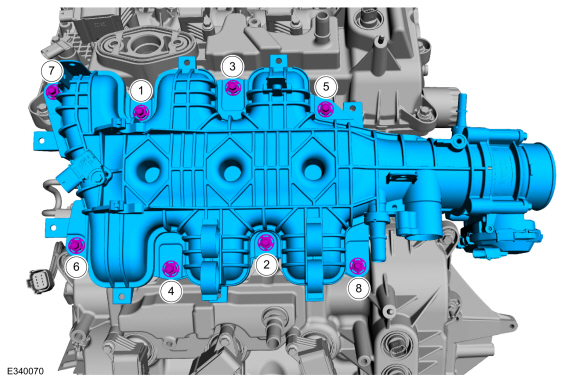
If gaskets were discarded install new intake manifold gaskets.
-
NOTICE:
If the engine is repaired or replaced because of upper
engine failure, typically including valve or piston damage, check the
intake manifold for metal debris. If metal debris is found, install a
new intake manifold. Failure to follow these instructions can result in
engine damage.
Install the intake manifold and the bolts.
Torque:
Stage 1:
89 lb.in (10 Nm)
Stage 2:
45°
-
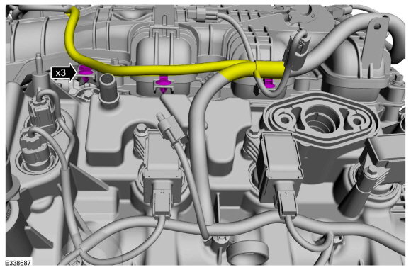
Install the pin-type retainers and wire harness to the intake manifold.
-
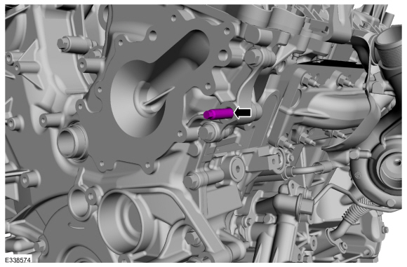
Install the generator stud bolt.
Torque:
71 lb.in (8 Nm)
-
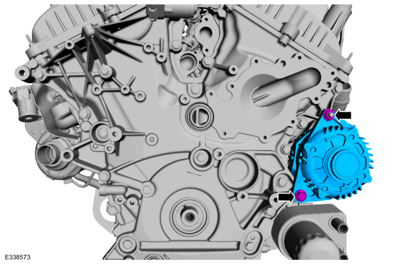
Install the generator, nut and bolt.
Torque:
35 lb.ft (48 Nm)
-
NOTE:
The new EGR to exhaust manifold connector comes lubricated, no lubricant needs to be applied.
Install the new EGR to exhaust manifold connector.
Torque:
125 lb.ft (170 Nm)
-
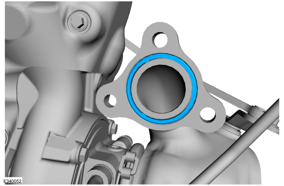
NOTE:
If the O-ring is replaced do not apply lubricant to the new O-ring, it will come already applied.
Verify the outlet O-ring is installed and in good condition. Install new O-ring if damaged or missing.
-
-
Position the EGR outlet tube into the intake manifold and hand start the bolt.
-
Position the end nut to the EGR valve tube and hand start.
-
Hand start the EGR bolts to the engine front cover.
-
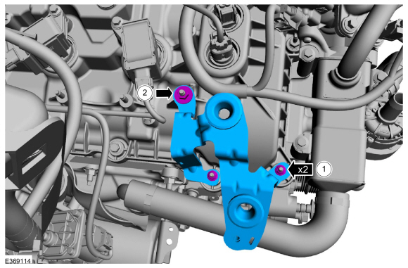
Tighten the EGR assembly bolts.
Torque:
Bolt 1 and 2 :
Stage 1:
71 lb.in (8 Nm)
Stage 2:
106 lb.in (12 Nm)
Bolt 3 and 4 :
Stage 3:
71 lb.in (8 Nm)
Stage 4:
106 lb.in (12 Nm)
-
-
Install the EGR cooler bracket onto the intake.
-
Install the bolt.
Torque:
71 lb.in (8 Nm)
-
Tighten the end nut to EGR valve tube.
Torque:
103 lb.ft (140 Nm)
-
-
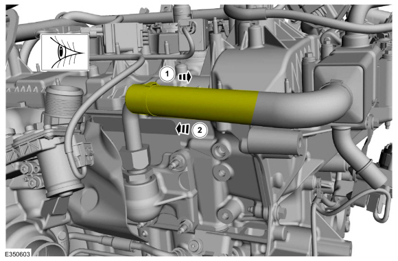
Pull back the heat sleeve and visually inspect the EGR heat tube for any twisting.
-
Return the heat sleeve back.
-
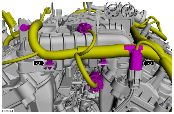
Connect the intake , knock and port injection fuel rail electrical connectors. Attach the pin-type retainers.
-
-
Attach the pin-type retainer.
-
Install the ground wire and stud.
Torque:
89 lb.in (10 Nm)
-
Connect the fuel injector electrical connectors.
-
Connect the cylinder head temperature sensor and camphaser electrical connectors.
-
-
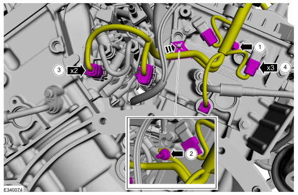
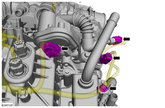
Position the engine wiring harness back and attach the wire harness retainers.
-
Connect the ignition coil-on-plug electrical connectors.
-
Connect the VCT oil control solenoid electrical connectors.
-
Connect the RH
TC electrical connector.
-
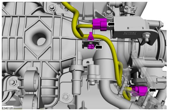
Attach the wire harness retainer and connect the EGR transducer and throttle body electrical connector.
-
-
Position the engine wiring harness back and attach the wire harness retainer.
-
Connect the EGR valve assembly.
-
Connect the EGR outlet temperature sensor.
-
Connect the exhaust manifold back pressure sensor.
-
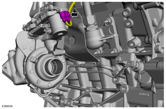
Connect the oil control solenoid electrical connector and attach the wire harness retainers.
-
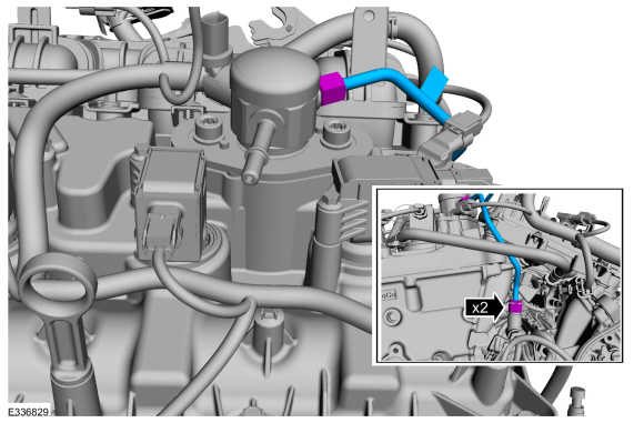
Remove the PCV tube.
Refer to: Spring Lock Couplings (310-00 Fuel System - General Information - 3.5L EcoBoost (272kW/370PS), General Procedures).
-
-
Position back the EVAP purge valve onto the intake manifold mounting tab.
-
Follow directions to connect the quick release coupling type 5.
Refer to: Quick Release Coupling (310-00 Fuel System - General Information - 3.5L EcoBoost (272kW/370PS), General Procedures).
-
Connect the MAPT electrical connector.
-
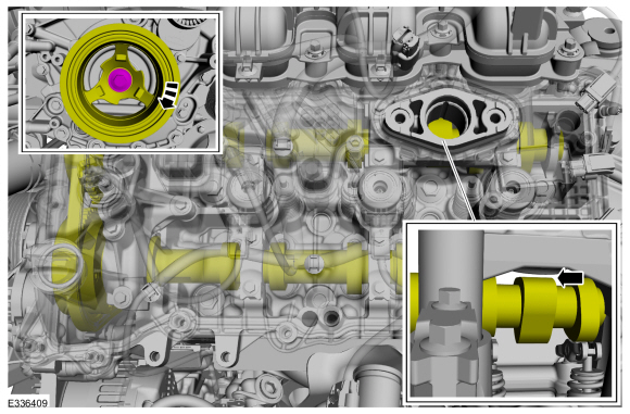
Rotate the crankshaft pulley bolt clockwise to position the
camshaft lobe for the high-pressure fuel pump drive is at BDC .
-
Apply clean engine oil to the high-pressure fuel pump
mounting pedestal bore, the drive lobe and the roller tappet. Install
the high-pressure fuel pump roller tappet.
-
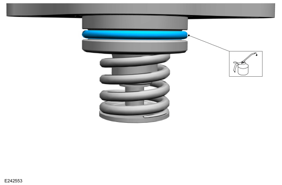
Inspect the high-pressure fuel pump mounting plate seal and
replace as needed. Lubricate the mounting plate seal with clean engine
oil.
Refer to: Specifications (303-01)
.
-
Install a new high-pressure fuel pump O-ring seal. Lubricate with clean engine oil.
Refer to: Specifications (303-01)
.
-
-
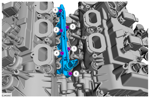
Install the high-pressure fuel pump and the new bolts.
Tighten the fuel high-pressure fuel pump bolts in the following 5
stages.
Torque:
Stage 1:
Finger tighten the bolts :
0 lb.in (0 Nm)
Stage 2:
Tighten bolt 1 :
1 turn(s)
Stage 3:
Tighten bolt 2 :
1 turn(s)
Stage 4:
Repeat stages 2 and 3, until reaching :
177 lb.in (20 Nm)
Stage 5:
Tighten bolts 1 and 2, in sequence an additional :
45°
 |
|
-
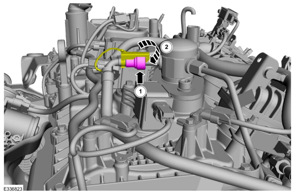
NOTE:
Calculate the correct torque wrench setting for the following torque using the Torque Wrench Adapter Formulas.
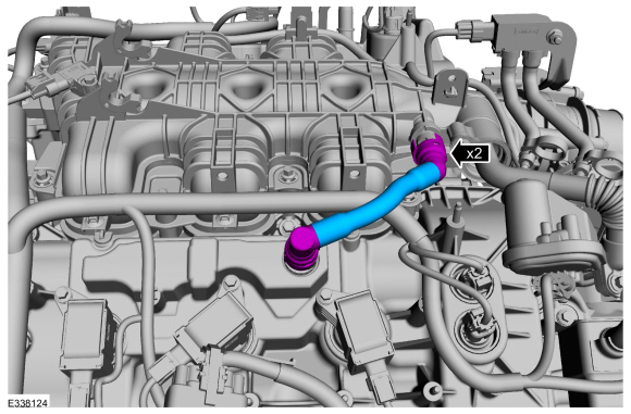
NOTE:
Make sure that a new high-pressure fuel pump to fuel rail high-pressure fuel tube is installed.
-
Install the high-pressure fuel pump to fuel rail
high-pressure fuel tube and tighten the flare nuts finger tight.
-
NOTICE:
In stage 3, if the torque required to tighten any
flare nut on the new high-pressure fuel tube reaches or exceeds 55 lb.ft
(75 Nm), then that high pressure fuel tube must be discarded and
replaced with another new high-pressure fuel tube
Tighten the high-pressure fuel pump to fuel rail high-pressure fuel tube flare nuts.
Torque:
Stage 1:
80 lb.in (9 Nm)
Stage 2:
97 lb.in (11 Nm)
Stage 3:
30°
Stage 4:
55°
 |
|
-
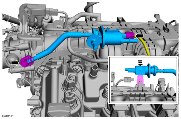
NOTICE:
The spring lock coupling must be installed onto the fuel
tube end along the centerline. The assembly is complete when the tube
end bottoms out on the spring lock coupling with an audible click / snap
feel. Correct assembly should be verified by pulling back on the spring
lock coupling end.
-
Connect the high-pressure fuel pump supply line and then connect the spring lock coupling.
Refer to: Spring Lock Couplings (310-00 Fuel System - General Information - 3.5L EcoBoost (272kW/370PS), General Procedures).
-
Install the secondary latch.
-
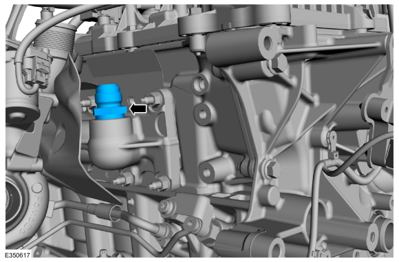
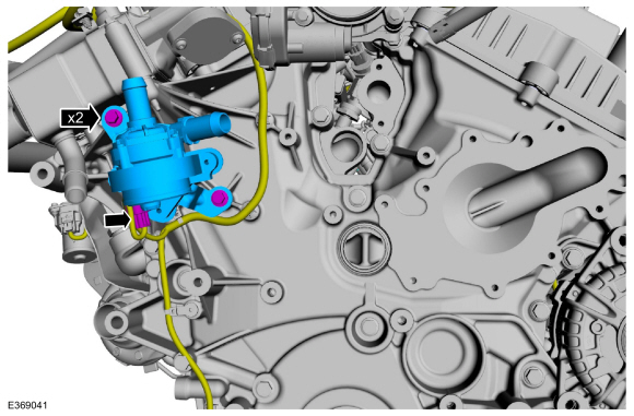
Install the cabin heater coolant pump, bolts and connect the electrical connector.
Torque:
89 lb.in (10 Nm)
-
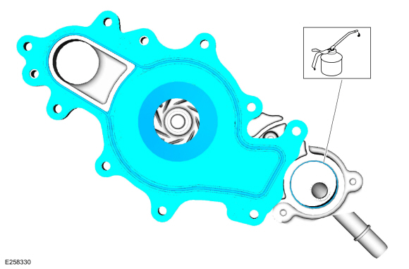
Install a new coolant pump gasket and lubricate the O-ring seal with clean engine coolant.
Material: Motorcraft® Yellow Prediluted Antifreeze/Coolant
/ VC-13DL-G
(WSS-M97B57-A2)
-
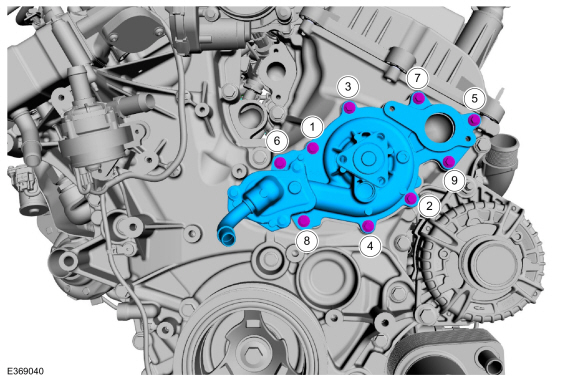
Install the coolant pump and the bolts.
Torque:
Stage 1:
89 lb.in (10 Nm)
Stage 2:
45°
-
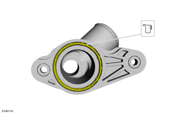
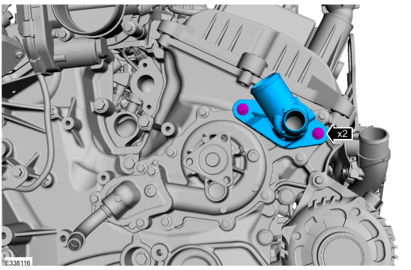
Lubricate the O-ring seal with clean engine coolant.
Material: Motorcraft® Yellow Prediluted Antifreeze/Coolant
/ VC-13DL-G
(WSS-M97B57-A2)
-
Install the water pump outlet connector and the bolts.
Torque:
Stage 1:
89 lb.in (10 Nm)
Stage 2:
45°
-
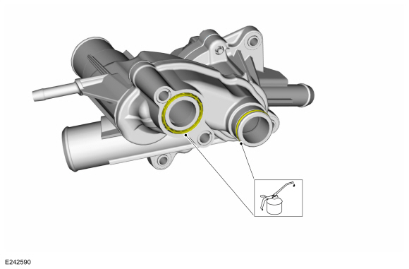
Lubricate the O-ring seals with clean engine coolant.
Material: Motorcraft® Yellow Prediluted Antifreeze/Coolant
/ VC-13DL-G
(WSS-M97B57-A2)
-
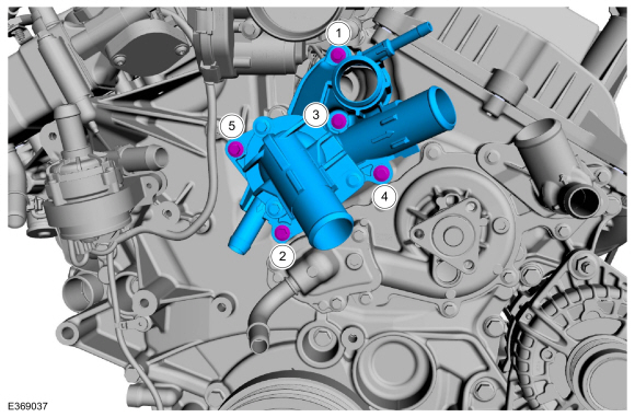
-
Install the thermostat housing and the bolts.
Torque:
Stage 1:
89 lb.in (10 Nm)
Stage 2:
45°
-
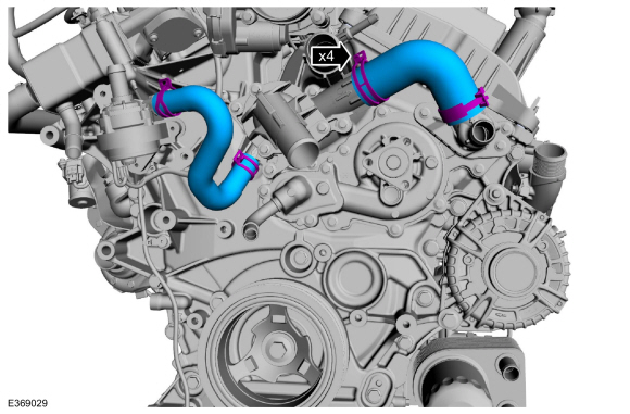
Install the coolant hoses.
Use the General Equipment: Hose Clamp Remover/Installer
-
-
Install the coolant pump pulley and the bolts.
Torque:
18 lb.ft (24 Nm)
-
Install the accessory drive belt tensioner, idler pulley and the bolts.
Torque:
18 lb.ft (25 Nm)
-
Install the LH engine mount bracket and the bolts.
Torque:
55 lb.ft (75 Nm)
-
Install the RH engine mount bracket and the bolts.
Torque:
55 lb.ft (75 Nm)
-
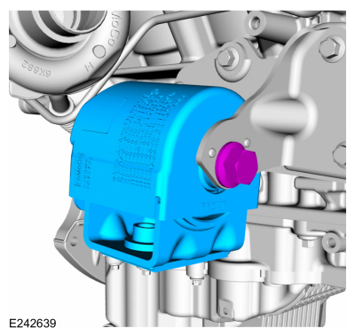
Install the RH engine mount and the bolt.
Torque:
258 lb.ft (350 Nm)
-
Install the CAC tube bracket and the nuts.
Torque:
53 lb.in (6 Nm)
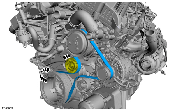
NOTICE:
During the removal or installation of components, cap, tape or
otherwise appropriately protect all openings and tubes/fittings to
prevent the ingress of dirt or other contamination. Remove caps, tape
and other protective materials prior to installation.
-
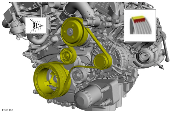
Rotate the accessory drive belt tensioner counter clockwise and install the accessory drive belt.
-
After installation, make sure the accessory drive belt is correctly seated on all pulleys.
-
-
Install the CAC support and nuts.
Torque:
53 lb.in (6 Nm)
-
Install the washer and nut.
Torque:
71 lb.in (8 Nm)
-
Install and connect the coolant hoses.
Use the General Equipment: Hose Clamp Remover/Installer
-
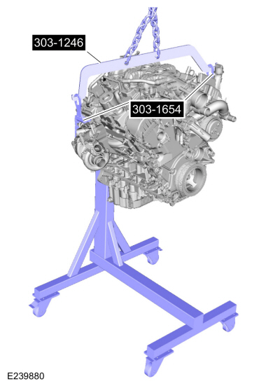
Install Special Service Tool: 303-1246
Engine Spreader Bar.
, 303-1654
Lift Eyes.
Use the General Equipment: Floor Crane
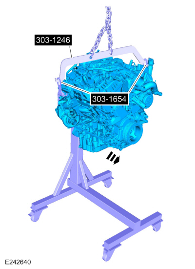
-
Remove the engine from the mounting stand.
Use Special Service Tool: 303-1246
Engine Spreader Bar.
, 303-1654
Lift Eyes.
Use the General Equipment: Floor Crane
Use the General Equipment: Mounting Stand
-
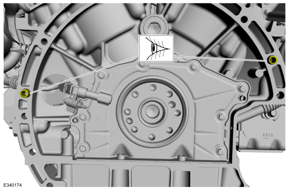
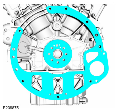
Inspect the engine block dowels. If the dowels are damaged or missing, install new engine block dowels.
-
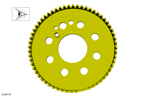
Inspect the ignition pulse ring for damage. If the ignition
pulse ring has been dropped or has any visual damage, it must be
replaced.
-
Install the crankshaft sensor ring and the engine-to-transmission spacer plate.
-
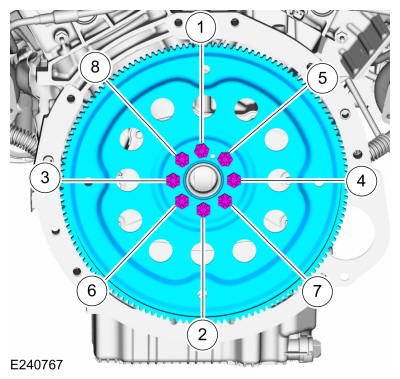
NOTE:
The offset hole may be used in four locations.
Install the flexplate and the bolts.
Torque:
59 lb.ft (80 Nm)
DISASSEMBLY
Remove the piston rings and discard.
Remove the piston pin retainers and discard...
Special Tool(s) /
General Equipment
303-1246Engine Spreader BarTKIT-2006UF-FLMTKIT-2006UF-ROW
303-1654Lift Eyes
307-346
(T97T-7902-A)
Retainer, Torque ConverterTKIT-1998-LM (NavigatoR)TKIT-1997-F/FLM/LT
Floor Crane
Trolley Jack
Hose Clamp Remover/Installer
Wooden Block
Materials
Name
Specification
Motorcra..
Other information:
Removal
NOTE:
Removal steps in this procedure may contain installation details.
Detach the clips and remove the lower steering column opening cover.
Detach the clips and remove the instrument panel lower side trim panel.
Detach the clips and remove the instrument panel upper s..
A Clutch Assembly
A Clutch
For A clutch operation, REFER to: A Clutch (307-01 Automatic Transmission - 10-Speed Automatic Transmission – 10R80, Description and Operation).
A Clutch
Condition
Possible Sources
Action
A clutch does not apply
SSA mechanically stuck OFF
INSTALL a new ..

 Piston. Disassembly and Assembly of Subassemblies
 Engine. Installation