Lincoln Navigator: Engine - 3.5L EcoBoost (272kW/370PS) / Piston. Disassembly and Assembly of Subassemblies
DISASSEMBLY
-
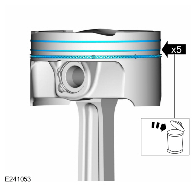
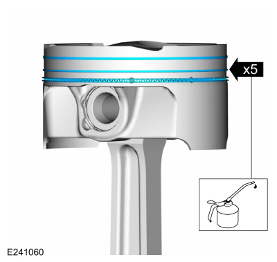
Remove the piston rings and discard.
 |
-
-
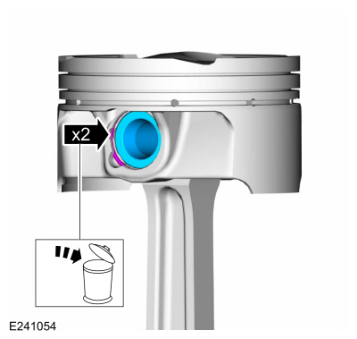
Remove the piston pin retainers and discard.
-
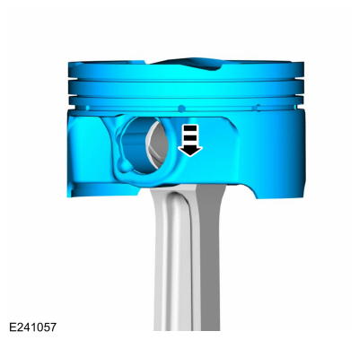
Remove the piston pin.
-
Remove the piston pin retainers and discard.
 |
-
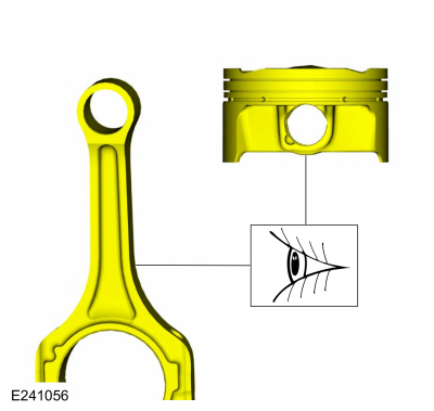
NOTE: If the piston and connecting rod are to be reinstalled, they must be assembled in the same orientation. Mark the piston orientation to the connecting rod for reassembly.
Remove the piston from the connecting rod.
 |
-
Inspect the piston and connecting rod.
Refer to: Piston Inspection (303-00 Engine System - General Information, General Procedures).
 |
ASSEMBLY
-
If the piston and/or connecting rod are being installed
new, the piston rod orientation marks and the arrow on the top of the
dome of the piston should be facing toward the front of the engine
block.
 |
-
Install the piston to the connecting rod.
 |
-
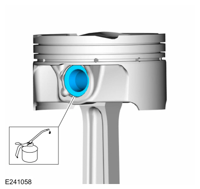
Lubricate with clean engine oil and install the piston pin.
Refer to: Specifications (303-01C) .
 |
-
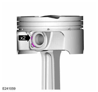
NOTE: The piston pin retaining clip gap orientation must be toward the top or dome of piston.
Install the piston pin retainers.
 |
-
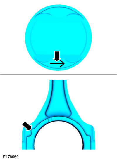
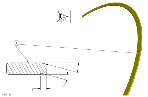
Inspect the lower compression ring to identify the
orientation. The top of the lower compression ring will be angled at the
top and notched on the bottom.
-
Top Side.
-
Top Side.
 |
-
Lubricate with clean engine oil and install the piston rings.
Refer to: Specifications (303-01C) .
 |
-
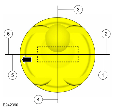
NOTE: The piston compression upper ring should be installed with the "O" mark on the ring face pointing up toward the top of the piston.
NOTE: The arrow on the top of the piston indicates the front of the engine.
-
Center line of the piston parallel to the wrist pin bore.
-
Upper compression ring gap location.
-
Upper oil control segment ring gap location.
-
Lower oil control segment ring gap location.
-
Lower compression ring gap location.
-
Spacer oil control ring gap location.
-
Center line of the piston parallel to the wrist pin bore.
 |

 Engine. Assembly
Special Tool(s) /
General Equipment
100-002
(TOOL-4201-C)
Holding Fixture with Dial Indicator Gauge
205-142
(T80T-4000-J)
Installer, Differential Bearing Cone
205-149
(T80T-4000-R)
Installer, Spindle Bearing
205-153
(T80T-4000-W)
Handle
303-102Installer, Crankshaft Pulley
303-1246Engine Spreader BarTKIT-2006UF-FLMTK..
Other information:
Lincoln Navigator 2018-2026 Workshop Manual: Front Floor Panel Side Member. Removal and Installation
Special Tool(s) / General Equipment 6.5 mm Drill Bit Scraper for Straight Edges Rivet Gun Self-Piercing Rivet (SPR) Remover/Installer Belt Sander Hot Air Gun Locking Pliers Materials Name Specification Metal Bonding AdhesiveTA-1, TA-1-B, 3M™ 08115, LORD Fusor® 108B, Henkel Teroson EP 5055 - Seam S..
Lincoln Navigator 2018-2026 Workshop Manual: Crankshaft Pulley. Removal and Installation
Special Tool(s) / General Equipment 303-102Installer, Crankshaft Pulley Strap Wrench Three Leg Puller Removal NOTICE: During engine repair procedures, cleanliness is extremely important. Any foreign material, including any material created while cleaning gasket surfaces, that enters the oil passages, coolant passages or the oil pan may cause en..
Categories
- Manuals Home
- 4th Gen Lincoln Navigator Service Manual (2018 - 2026)
- Body Control Module (BCM). Removal and Installation
- Body and Paint
- Vehicle Dynamics Control Module (VDM). Removal and Installation
- SYNC Module [APIM]. Removal and Installation
- Front Bumper Cover. Removal and Installation
Wheel to Hub Runout Minimization. General Procedures
Check
NOTE: Wheel-to-hub optimization is important. Clearance between the wheel and hub can be used to offset or neutralize the Road Force® or run-out of the wheel and tire assembly. For every 0.001 inch of wheel-to-hub clearance, the Road Force® can be affected between 1 and 3 pounds depending on the tire stiffness.
NOTE: The example below illustrates how the clearance between the wheel and the hub can be used to offset the high spot of radial run-out or Road Force®. Following the procedure will make sure of the best optimization.
Position the wheel and tire assembly on the vehicle so that the high spot location of radial run-out or Road Force® is at the 6 o'clock position and