Lincoln Navigator: Engine - 3.5L EcoBoost (272kW/370PS) / Cylinder Head. Disassembly and Assembly of Subassemblies
Special Tool(s) / General Equipment
 |
303-1249 Valve Spring Compressor TKIT-2006UF-FLM TKIT-2006UF-ROW |
 |
303-1418 Compressor, Valve Spring TKIT-2008ET-FLM TKIT-2008ET-ROW |
 |
303-1567 Sizer, Teflon Seal TKIT-2010C-FLM |
 |
303-300
(T87C-6565-A)
Set, Valve Spring Compressor TKIT-1988-FESTIVA T88C-1000-ST TKIT-1988-TRACER TKIT-2009TC-F |
 |
303-350
(T89P-6565-A)
Compressor, Valve Spring TKIT-1990-LMH TKIT-1989-F TKIT-1989-FM TKIT-1989-FLM |
 |
303-470
(T94P-6510-CH)
Installer, Valve Stem Oil Seal TKIT-1994-LMH/MH2 TKIT-2009TC-F TKIT-1994-FH/FMH/FLMH |
 |
307-005
(T59L-100-B)
Slide Hammer |
 |
310-205 Fuel Injector Brush |
 |
310-206 Remover, Fuel Injector TKIT-2009A-FLM |
 |
310-207 Installer, Fuel Injector Seal Assembly TKIT-2009A-FLM |
Materials
| Name | Specification |
|---|---|
| Motorcraft® Metal Surface Prep Wipes ZC-31-B |
- |
DISASSEMBLY
NOTICE: The turbocharger compressor vanes can be damaged by even the smallest particles. When removing any turbocharger or engine air intake system component, ensure that no debris enters the system. Failure to do so may result in damage to the turbocharger.
NOTICE: During engine repair procedures, cleanliness is extremely important. Any foreign material, including any material created while cleaning gasket surfaces, that enters the oil passages, coolant passages or the oil pan, can cause engine failure.
LH cylinder head
-
-
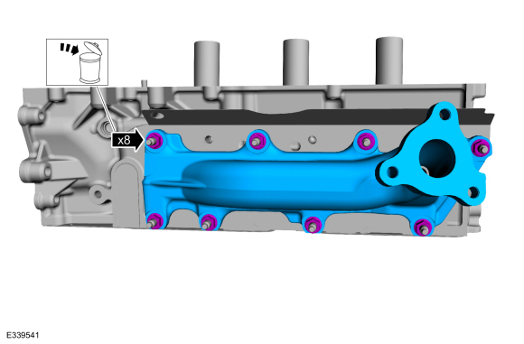
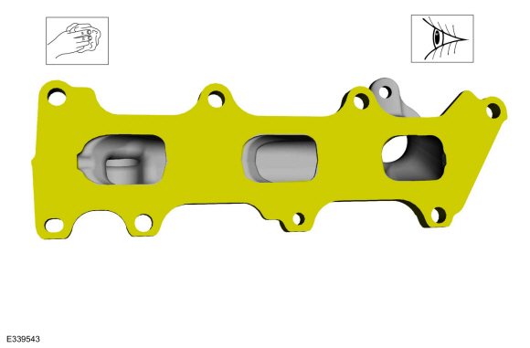
Remove the nuts and the exhaust manifold.
-
Discard the nuts.
-
Remove the nuts and the exhaust manifold.
 |
-
-
Remove the discard the exhaust manifold gasket.
-
Remove and discard the studs.
-
Remove the discard the exhaust manifold gasket.
 |
-
-
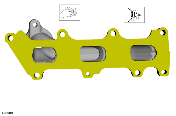
Clean and inspect the exhaust manifold.
Refer to: Exhaust Manifold Cleaning and Inspection (303-00 Engine System - General Information, General Procedures).
-
NOTICE: Do not use metal scrapers, wire brushes, power abrasive discs or other abrasive means to clean the sealing surfaces. These may cause scratches and gouges resulting in leak paths. Use a plastic scraper to clean the sealing surfaces.
Clean the exhaust manifold mating surface of the cylinder head with metal surface prep wipes. Follow the directions on the packaging.
Material: Motorcraft® Metal Surface Prep Wipes / ZC-31-B
-
Clean and inspect the exhaust manifold.
 |
-
-
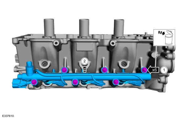
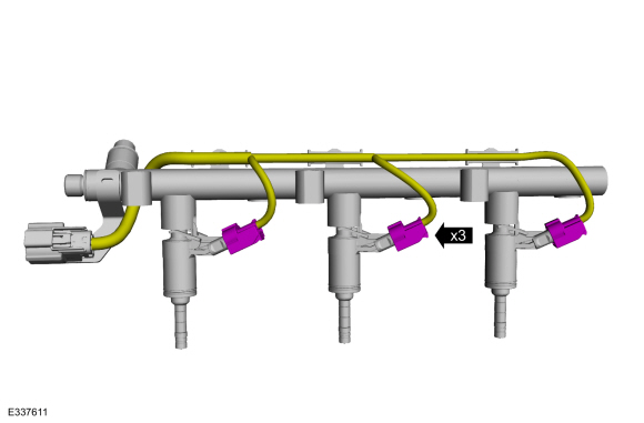
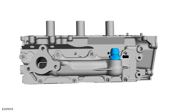
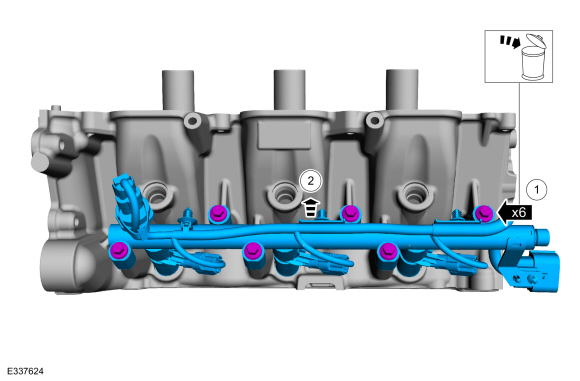
Remove and discard the direct injection fuel rail mounting bolts.
-
NOTICE: Pull out the fuel rails in the direction of the fuel injector axis or damage may occur to the fuel injectors.
NOTE: When removing the fuel rails, the fuel injectors may remain in the cylinder heads and require the use of a Fuel Injector Remover tool to extract. Wiggling the injector by hand to break it loose may allow the injector to be removed by hand.
Remove the direct injection fuel rail and the fuel injectors.
-
Remove and discard the direct injection fuel rail mounting bolts.
 |
-
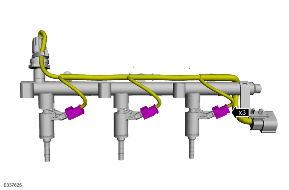
Disconnect the fuel injector electrical connectors.
 |
-
-
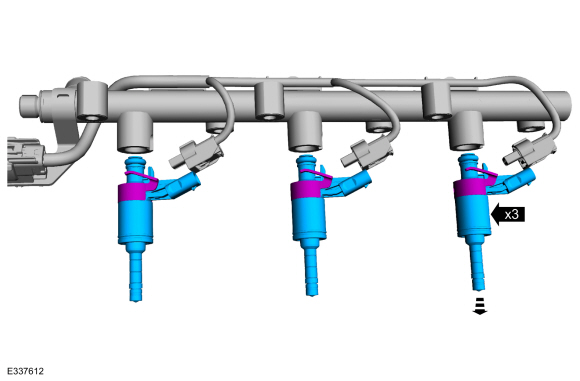
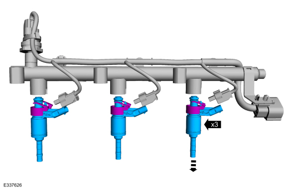
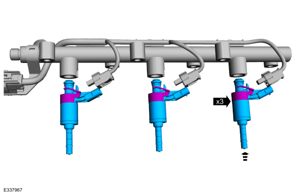
Release the fuel injector retaining clips.
-
Remove the fuel injectors from the fuel rail.
-
Release the fuel injector retaining clips.
 |
-
Remove and discard the clips from all of the fuel
injectors including any injectors that have remained in the cylinder
head.
 |
-
-
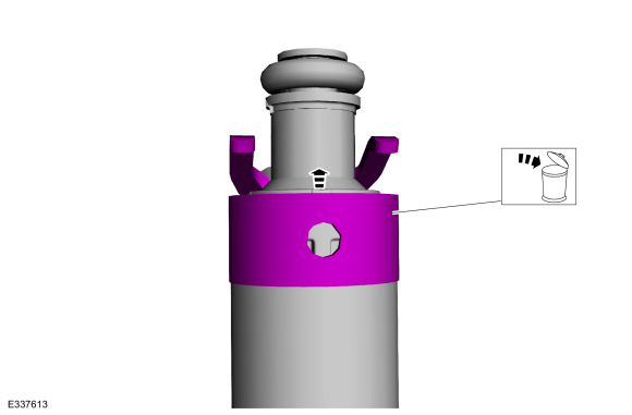
Remove and discard the fuel injector O-ring seals.
-
NOTE: Note the correct orientation of the fuel injector support rings for correct installation of the new fuel injector support rings.
Remove and discard the fuel injector support rings.
-
Remove and discard the fuel injector O-ring seals.
 |
-
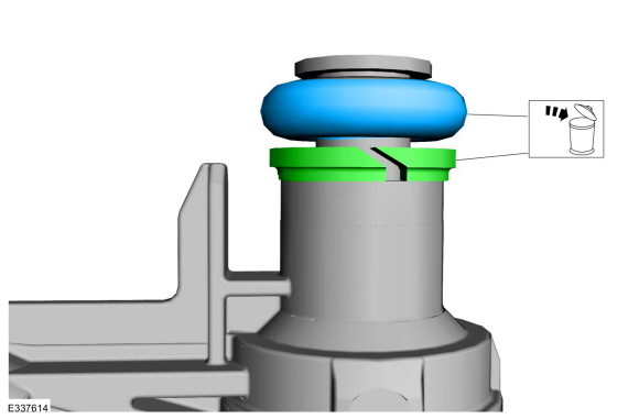
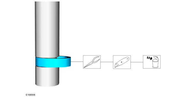
NOTICE: Use care when removing the lower Teflon® seals, not to scratch, nick or gouge the fuel injectors.
NOTICE: Do not attempt to cut the lower Teflon® seal without first pulling it away from the fuel injector or damage to the injector may occur.
-
Pull the lower Teflon® seal away from the injector.
-
Carefully cut and discard the lower fuel injector Teflon® seals.
-
Pull the lower Teflon® seal away from the injector.
 |
RH cylinder head
-
Remove the EGR to exhaust manifold connector.
 |
-
-
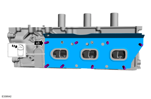
Remove the nuts and the exhaust manifold.
-
Discard the nuts.
-
Remove the nuts and the exhaust manifold.
 |
-
Remove and discard the studs and the exhaust manifold gasket.
 |
-
-
Clean and inspect the exhaust manifold.
Refer to: Exhaust Manifold Cleaning and Inspection (303-00 Engine System - General Information, General Procedures).
-
NOTICE: Do not use metal scrapers, wire brushes, power abrasive discs or other abrasive means to clean the sealing surfaces. These may cause scratches and gouges resulting in leak paths. Use a plastic scraper to clean the sealing surfaces.
Clean the exhaust manifold mating surface of the cylinder head with metal surface prep wipes. Follow the directions on the packaging.
Material: Motorcraft® Metal Surface Prep Wipes / ZC-31-B
-
Clean and inspect the exhaust manifold.
 |
-
-
Remove and discard the direct injection fuel rail mounting bolts.
-
NOTICE: Pull out the fuel rails in the direction of the fuel injector axis or damage may occur to the fuel injectors.
NOTE: When removing the fuel rails, the fuel injectors may remain in the cylinder heads and require the use of a Fuel Injector Remover tool to extract. Wiggling the injector by hand to break it loose may allow the injector to be removed by hand.
Remove the direct injection fuel rail and the fuel injectors.
-
Remove and discard the direct injection fuel rail mounting bolts.
 |
-
Disconnect the fuel injector electrical connectors.
 |
-
-
Release the fuel injector retaining clips.
-
Remove the fuel injectors from the fuel rail.
-
Release the fuel injector retaining clips.
 |
-
Remove and discard the clips from all of the fuel
injectors including any injectors that have remained in the cylinder
head.
|
-
-
Remove and discard the fuel injector O-ring seals.
-
NOTE: Note the correct orientation of the fuel injector support rings for correct installation of the new fuel injector support rings.
Remove and discard the fuel injector support rings.
-
Remove and discard the fuel injector O-ring seals.
|
-
NOTICE: Use care when removing the lower Teflon® seals, not to scratch, nick or gouge the fuel injectors.
NOTICE: Do not attempt to cut the lower Teflon® seal without first pulling it away from the fuel injector or damage to the injector may occur.
-
Pull the lower Teflon® seal away from the injector.
-
Carefully cut and discard the lower fuel injector Teflon® seals.
-
Pull the lower Teflon® seal away from the injector.
|
All cylinder heads
-
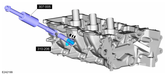
NOTICE: Use minimal force to remove the fuel injectors that remained in the cylinder head with the Fuel Injector Remover tool or damage to the fuel injector assembly may occur.
Using the special tools, remove the fuel injectors that remained in the cylinder head.
Use Special Service Tool: 307-005 (T59L-100-B) Slide Hammer. , 310-206 Remover, Fuel Injector.
 |
-
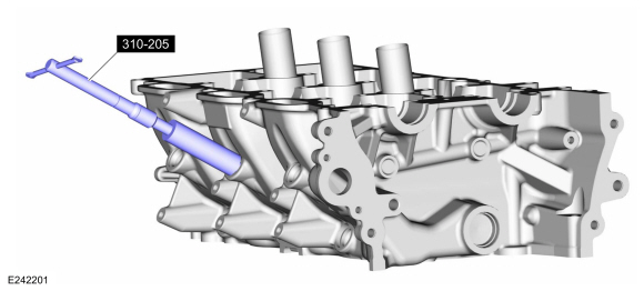
NOTICE: Make sure to thoroughly clean any residual fuel or foreign material from the cylinder head, block and the general surrounding area of the fuel rails and injectors.
NOTICE: Do not use compressed air to clean the tip of the fuel injector.
NOTICE: Do not use a brush to clean the tip of the fuel injector.
Using the special tool, clean the cylinder head fuel injector bores.
Use Special Service Tool: 310-205 Fuel Injector Brush.
 |
-
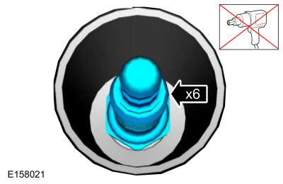
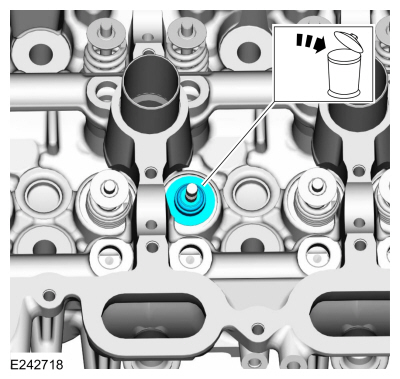
Remove the spark plugs.
 |
-
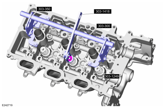
NOTE: LH shown, RH similar.
NOTE: If the components are to be reinstalled, they must be installed in the same positions. Mark the components for installation into their original locations.
Using the special tools, remove the valve collet, valve spring retainer and the valve spring.
Use Special Service Tool: 303-300 (T87C-6565-A) Set, Valve Spring Compressor. , 303-350 (T89P-6565-A) Compressor, Valve Spring. , 303-1249 Valve Spring Compressor. , 303-1418 Compressor, Valve Spring.
 |
-
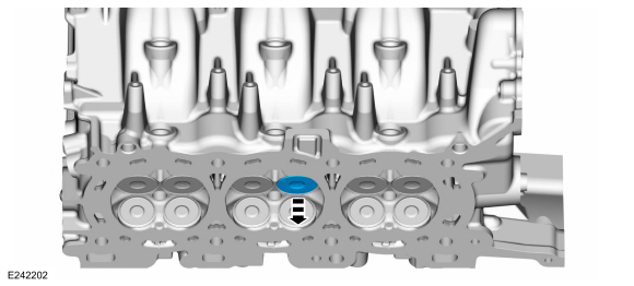
Remove and discard the valve stem seal.
 |
-
Remove the valve.
 |
-
Repeat the previous 3 steps for each valve.
ASSEMBLY
All cylinder heads
-
Install the valve.
 |
-
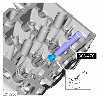
NOTE: Lubricate the valve stem seal with clean engine oil prior to installation.
Using the special tool, install the valve stem seal.
Refer to: Specifications (303-01) .
Use Special Service Tool: 303-470 (T94P-6510-CH) Installer, Valve Stem Oil Seal.
 |
-
Using the special tools, install the valve spring, valve spring retainer and the valve collet.
Use Special Service Tool: 303-300 (T87C-6565-A) Set, Valve Spring Compressor. , 303-350 (T89P-6565-A) Compressor, Valve Spring. , 303-1249 Valve Spring Compressor. , 303-1418 Compressor, Valve Spring.
|
-
Repeat the previous 3 steps for each valve.
-
Install the spark plugs.
Torque: 133 lb.in (15 Nm)
|
RH cylinder head
-
NOTICE: Do not lubricate the new lower Teflon® fuel injector seals.
-
Install the Arbor on the fuel injector tips.
Use Special Service Tool: 310-207 Installer, Fuel Injector Seal Assembly.
-
NOTICE: Once the Teflon® seal is installed on the Teflon® Seal Guide, it should immediately be installed onto the fuel injector to avoid excessive expansion of the Teflon® seal.
NOTE: Make sure that new lower fuel injector Teflon® seals are installed.
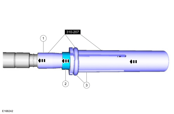
Install the new Teflon® seals onto the Arbor, using the Pusher Tool (part of the Fuel Injector Seal Installer), slide the Teflon® seals along the Arbor.
-
Using the Pusher Tool, slide the Teflon® seals
off of the Teflon® Seal Guide and into the groove on the fuel injectors.
Use Special Service Tool: 310-207 Installer, Fuel Injector Seal Assembly.
-
Install the Arbor on the fuel injector tips.
 |
-
NOTICE: Install the fuel injectors into the cylinder head within 15 minutes of sizing the seals due to Teflon® seal expansion.
NOTE: Make sure the Teflon® seal is fully seated in the groove on the fuel injector before sizing the Teflon® seal.
-
Some Teflon® seal massaging with your fingers
before the Teflon® seal sizer tool is installed will aid in installing
the Teflon® seal sizer tool.
-
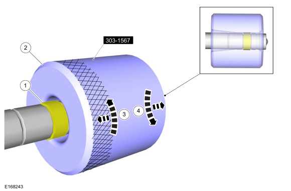
Position the Teflon® Seal Sizer tool with the
larger opening towards the Teflon® seal. Push while turning the Teflon®
Seal Sizer tool 180 degrees.
Use Special Service Tool: 303-1567 Sizer, Teflon Seal.
-
Once the Teflon® Seal Sizer tool is installed,
check and make sure the Teflon® seal is in the sizing portion of the
Teflon® Seal Sizer tool. After one minute, turn the Teflon® Seal Sizer
tool back 180 degrees and remove.
-
After one minute, turn the Teflon® seal sizer tool back 180 degrees and remove.
-
Some Teflon® seal massaging with your fingers
before the Teflon® seal sizer tool is installed will aid in installing
the Teflon® seal sizer tool.
 |
-
-
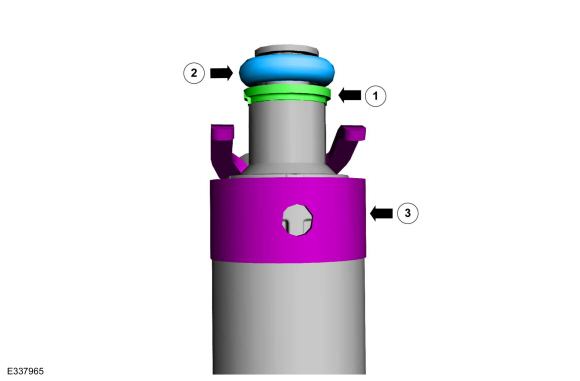
NOTICE: The large diameter step of the backup ring must go up towards the new O-ring seal. Improperly installed backup rings may cause the fuel system to leak.
Install the fuel injector backup ring.
-
NOTICE: Use fuel injector O-ring seals that are made of special fuel-resistant material. The use of ordinary O-ring seals may cause the fuel system to leak. Do not reuse the O-ring seals.
NOTE: Do not lubricate the new lower Teflon® fuel injector seals.
Install the new fuel injector O-ring seals. Lubricate the new fuel injector O-ring seals with clean engine oil.
Refer to: Specifications (303-01) .
-
Install the new the fuel injector retaining clip.
-
 |
-
NOTICE: The anti-rotation finger of the fuel injector must slip into the groove of the fuel rail cup.
Install the fuel injectors into the fuel rail.
 |
-
Connect the fuel injector electrical connectors.
|
-
NOTE: Do not lubricate the new lower Teflon® fuel injector seals.
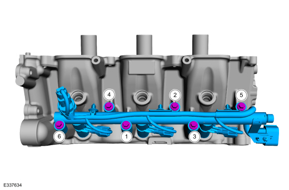
NOTE: Make sure that new fuel rail mounting bolts are installed.
NOTE: Push down on the fuel rail above the injectors.
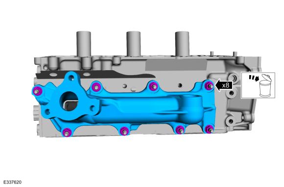
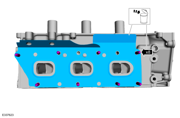
-
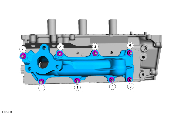
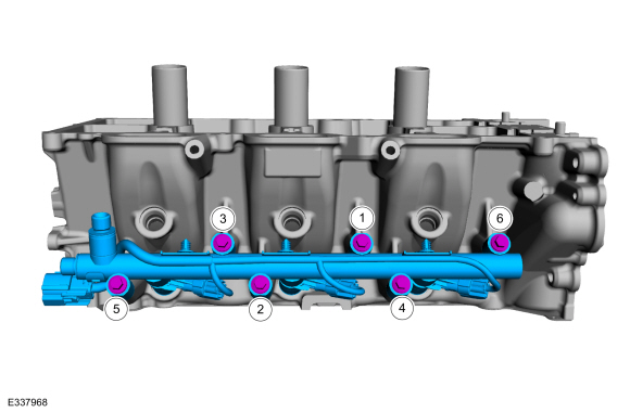
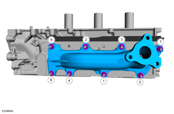
Install the fuel injectors and direct injection
fuel rail assembly into the cylinder head. Tighten the bolts in sequence
shown in 2 stages.
Torque:
Stage 1: 89 lb.in (10 Nm)
Stage 2: 45°
-
Install the fuel injectors and direct injection
fuel rail assembly into the cylinder head. Tighten the bolts in sequence
shown in 2 stages.
 |
-
NOTE: Install short end of stud into cylinder head assembly.
-
Loosely install the new studs into the cylinder head.
-
Tighten the studs.
Torque: 115 lb.in (13 Nm)
-
Install the new exhaust manifold gasket.
-
Loosely install the new studs into the cylinder head.
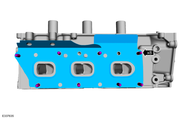 |
-
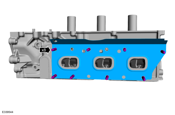
Install the exhaust manifold and the new nuts. Tighten the nuts in sequence shown in 2 stages.
Torque:
Stage 1: 142 lb.in (16 Nm)
Stage 2: 16 lb.ft (22 Nm)
 |
-
Install the EGR to exhaust manifold connector.
Torque: 125 lb.ft (170 Nm)
|
LH cylinder head
-
NOTICE: Do not lubricate the new lower Teflon® fuel injector seals.
-
Install the Arbor on the fuel injector tips
Use Special Service Tool: 310-207 Installer, Fuel Injector Seal Assembly.
-
NOTICE: Once the Teflon® seal is installed on the Teflon® Seal Guide, it should immediately be installed onto the fuel injector to avoid excessive expansion of the Teflon® seal.
NOTE: Make sure that new lower fuel injector Teflon® seals are installed.
Install the new Teflon® seals onto the Arbor, using the Pusher Tool (part of the Fuel Injector Seal Installer), slide the Teflon® seals along the Arbor.
-
Using the Pusher Tool, slide the Teflon® seals
off of the Teflon® Seal Guide and into the groove on the fuel injectors.
Use Special Service Tool: 310-207 Installer, Fuel Injector Seal Assembly.
-
Install the Arbor on the fuel injector tips
|
-
NOTICE: Install the fuel injectors into the cylinder head within 15 minutes of sizing the seals due to Teflon® seal expansion.
NOTE: Make sure the Teflon® seal is fully seated in the groove on the fuel injector before sizing the Teflon® seal.
-
Some Teflon® seal massaging with your fingers
before the Teflon® seal sizer tool is installed will aid in installing
the Teflon® seal sizer tool.
-
Position the Teflon® Seal Sizer tool with the
larger opening towards the Teflon® seal. Push while turning the Teflon®
Seal Sizer tool 180 degrees.
Use Special Service Tool: 303-1567 Sizer, Teflon Seal.
-
Once the Teflon® Seal Sizer tool is installed,
check and make sure the Teflon® seal is in the sizing portion of the
Teflon® Seal Sizer tool. After one minute, turn the Teflon® Seal Sizer
tool back 180 degrees and remove.
-
After one minute, turn the Teflon® seal sizer tool back 180 degrees and remove.
-
Some Teflon® seal massaging with your fingers
before the Teflon® seal sizer tool is installed will aid in installing
the Teflon® seal sizer tool.
|
-
-
NOTICE: The large diameter step of the backup ring must go up towards the new O-ring seal. Improperly installed backup rings may cause the fuel system to leak.
Install the fuel injector backup ring.
-
NOTICE: Use fuel injector O-ring seals that are made of special fuel-resistant material. The use of ordinary O-ring seals may cause the fuel system to leak. Do not reuse the O-ring seals.
NOTE: Do not lubricate the new lower Teflon® fuel injector seals.
Install the new fuel injector O-ring seals. Lubricate the new fuel injector O-ring seals with clean engine oil.
Refer to: Specifications (303-01) .
-
Install the new the fuel injector retaining clip.
-
|
-
NOTICE: The anti-rotation finger of the fuel injector must slip into the groove of the fuel rail cup.
Install the fuel injectors into the fuel rail.
 |
-
Connect the fuel injector electrical connectors.
|
-
NOTE: Do not lubricate the new lower Teflon® fuel injector seals.
NOTE: Make sure that new fuel rail mounting bolts are installed.
NOTE: Push down on the fuel rail above the injectors.
-
Install the fuel injectors and direct injection
fuel rail assembly into the cylinder head. Tighten the bolts in sequence
shown in 2 stages.
Torque:
Stage 1: 89 lb.in (10 Nm)
Stage 2: 45°
-
Connect the fuel injector electrical connectors.
-
Install the fuel injectors and direct injection
fuel rail assembly into the cylinder head. Tighten the bolts in sequence
shown in 2 stages.
 |
-
NOTE: Install short end of stud into cylinder head assembly.
-
Loosely install the new studs into the cylinder head.
-
Tighten the studs.
Torque: 115 lb.in (13 Nm)
-
Install the new exhaust manifold gasket.
-
Loosely install the new studs into the cylinder head.
 |
-
Install the exhaust manifold and the new nuts. Tighten the nuts in sequence shown in 2 stages.
Torque:
Stage 1: 142 lb.in (16 Nm)
Stage 2: 16 lb.ft (22 Nm)
 |

 Piston. Disassembly and Assembly of Subassemblies
DISASSEMBLY
Remove the piston rings and discard.
Remove the piston pin retainers and discard...
Other information:
Lincoln Navigator 2018-2026 Workshop Manual: Rear Floor Panel. Removal and Installation
Special Tool(s) / General Equipment 6.5 mm Drill Bit Self-Piercing Rivet (SPR) Remover/Installer Belt Sander Blind Rivet Gun Knife Locking Pliers Materials Name Specification Metal Bonding AdhesiveTA-1, TA-1-B, 3M™ 08115, LORD Fusor® 108B, Henkel Teroson EP 5055 - Seam SealerTA-2-B, 3M™ 08308, LORD Fuso..
Lincoln Navigator 2018-2026 Workshop Manual: Restraints Control Module (RCM). Removal and Installation
Removal WARNING: The following procedure prescribes critical repair steps required for correct restraint system operation during a crash. Follow all notes and steps carefully. Failure to follow step instructions may result in incorrect operation of the restraint system and increases the risk of serious personal injury or death in a crash. NOTE: Removal steps in this..
Categories
- Manuals Home
- 4th Gen Lincoln Navigator Service Manual (2018 - 2026)
- Rear Bumper. Removal and Installation
- All Terrain Control Module (ATCM). Removal and Installation
- Transmission Fluid Level Check. General Procedures
- Brake Service Mode Activation and Deactivation. General Procedures
- Identification Codes. Description and Operation
Rear Drive Axle and Differential. Diagnosis and Testing
Symptom Chart(s)
Diagnostics in this manual assume a certain skill level and knowledge of Ford-specific diagnostic practices.
REFER to: Diagnostic Methods (100-00 General Information, Description and Operation).
Symptom Chart - Differential
Symptom Chart - Differential
Condition Actions Axle overheating GO to Pinpoint Test A Broken gear teeth on the ring gear or pinion GO to Pi