Lincoln Navigator: Engine - 3.5L EcoBoost (272kW/370PS) / Engine. Disassembly
Special Tool(s) /
General Equipment
 |
205-142
(T80T-4000-J)
Installer, Differential Bearing Cone |
 |
205-150
(T80T-4000-S)
Installer, Spindle Bearing |
 |
205-153
(T80T-4000-W)
Handle |
 |
303-1246
Engine Spreader Bar
TKIT-2006UF-FLM
TKIT-2006UF-ROW |
 |
303-1247
VCT Spark Plug Tube Seal Remover and Installer
TKIT-2006UF-FLM
TKIT-2006UF-ROW |
 |
303-1654
Lift Eyes |
 |
303-1655
Tool, Camshaft Holding |
 |
303-409
(T92C-6700-CH)
Remover, Crankshaft Seal
TKIT-1992-FH/FMH/FLMH
TKIT-1993-LMH/MH |
 |
307-005
(T59L-100-B)
Slide Hammer |
 |
310-205
Fuel Injector Brush |
 |
310-206
Remover, Fuel Injector
TKIT-2009A-FLM |
| Floor Crane |
| Three Leg Puller |
| Mounting Stand |
| Hose Clamp Remover/Installer |
| Long Nose Pliers |
Materials
| Name |
Specification |
Motorcraft® Silicone Gasket Remover
ZC-30-A, AZC-30-C |
-
|
Motorcraft® Metal Surface Prep Wipes
ZC-31-B |
-
|
Motorcraft® Metal Brake Parts Cleaner
PM-4-A, PM-4-B, APM-4-C |
-
|
NOTICE:
During engine repair procedures, cleanliness is extremely
important. Any foreign material, including any material created while
cleaning gasket surfaces that enters the oil passages, coolant passages
or the oil pan, can cause engine failure.
NOTICE:
The turbocharger compressor vanes can be damaged by even the
smallest particles. When removing any turbocharger or engine air intake
system component, ensure that no debris enters the system. Failure to do
so may result in damage to the turbocharger.
NOTICE:
Special attention needs to be given to the sealing ports for the
oil feed, the oil drain, and the coolant tubes, on turbocharged
engines. The sealing ports must be totally clean and free from O-ring
residue, have no damage to the sealing surface and the tubes to ensure
that there are no leaks or repeat repairs.
NOTE:
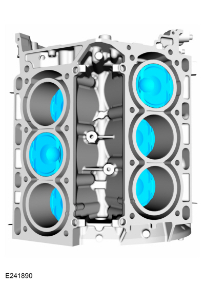
Refer to the exploded view under the Engine Component View in the Description and Operation.
-
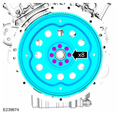
Remove the bolts and the flexplate.
-
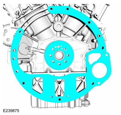
Remove the crankshaft sensor ring and the engine-to-transmission spacer plate.
-
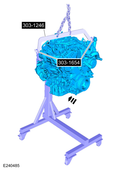
NOTE:
Install the engine stand bolts into the cylinder block
only. Do not install the bolts into the engine block skirt stiffener.
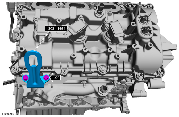
Mount the engine to the mounting stand.
Use Special Service Tool: 303-1246
Engine Spreader Bar.
, 303-1654
Lift Eyes.
Use the General Equipment: Floor Crane
Use the General Equipment: Mounting Stand
-
Remove the floor crane.
Remove Special Service Tool: 303-1246
Engine Spreader Bar.
, 303-1654
Lift Eyes.
Use the General Equipment: Floor Crane
-
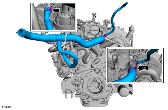
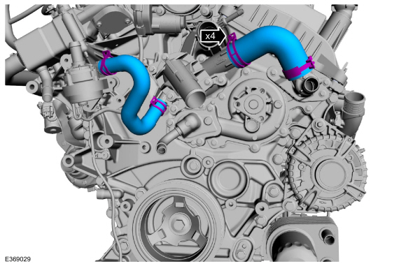
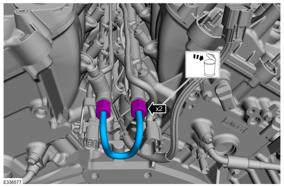
Disconnect and remove the coolant hoses.
Use the General Equipment: Hose Clamp Remover/Installer
-
-
Remove the nuts and the CAC support.
-
Remove the nuts and the CAC tube bracket.
-
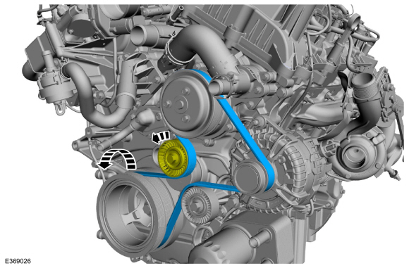
Rotate the accessory drive belt tensioner counter clockwise and remove the accessory drive belt.
-
-
Remove the bolt and the RH engine mount.
-
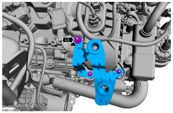
-
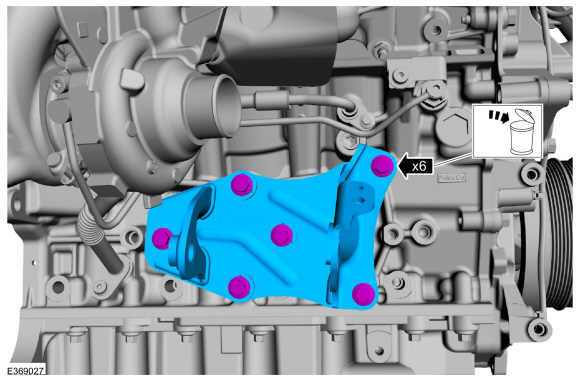
Remove the bolts and the RH engine mount bracket.
-
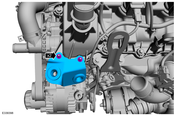
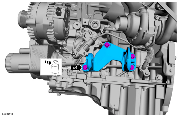
-
Remove the bolts and the LH engine mount bracket.
-
-
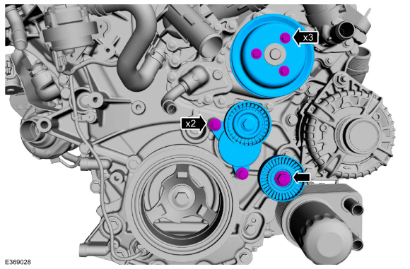
Remove the bolts and the coolant pump pulley.
-
Remove the bolts and the accessory drive belt tensioner
-
Remove the bolt and the idler pulley.
-
Remove the coolant hoses.
Use the General Equipment: Hose Clamp Remover/Installer
-
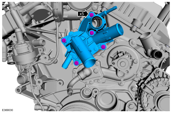
Remove the bolts and the thermostat housing.
-
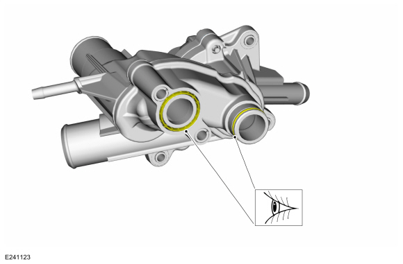
Inspect the O-ring seals and replace if necessary.
-
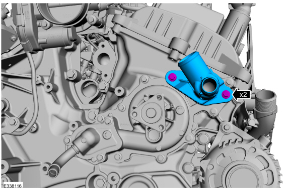
Remove the bolts and the water pump outlet connector.
-
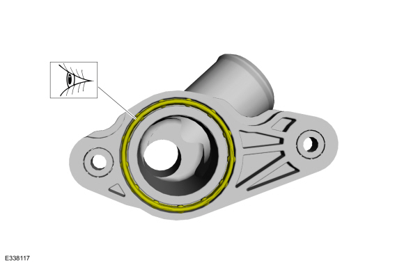
Inspect the O-ring seal and replace if necessary.
-
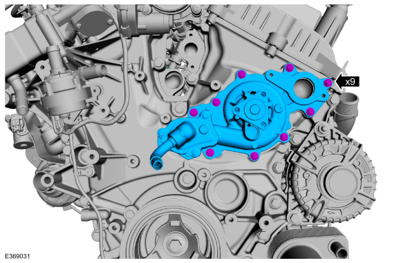
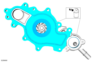
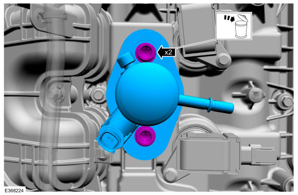
Remove the bolts and the coolant pump.
-
Remove and discard the coolant pump gasket and O-ring seal.
-
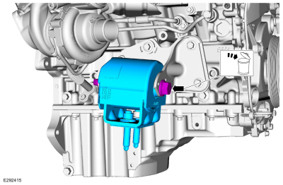
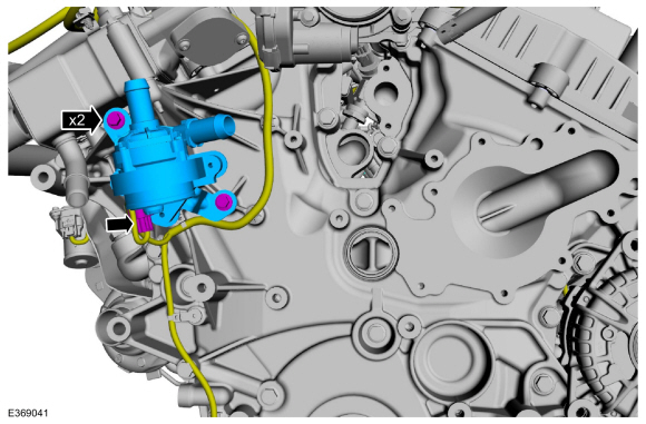
Disconnect the electrical connector, remove the bolts and the cabin heater coolant pump.
-
-
Remove the crankshaft pulley bolt and washer.
-
Using a three leg puller, remove the crankshaft pulley.
Use the General Equipment: Three Leg Puller
-
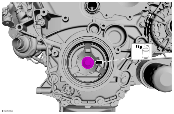
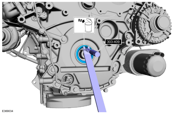
Using the special tool, remove and discard the crankshaft front seal.
Use Special Service Tool: 303-409
(T92C-6700-CH)
Remover, Crankshaft Seal.
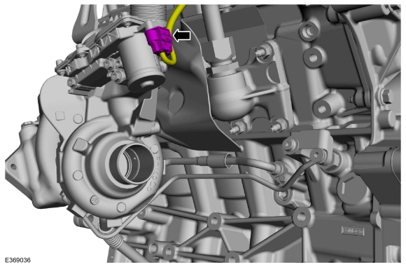
-
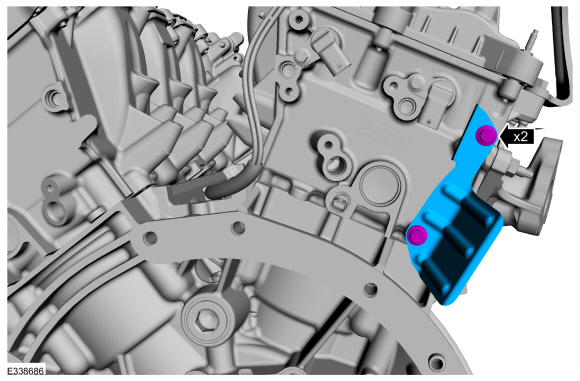
Disconnect the high-pressure fuel pump electrical connector.
-
-
Disconnect the secondary latch and position out of the way.
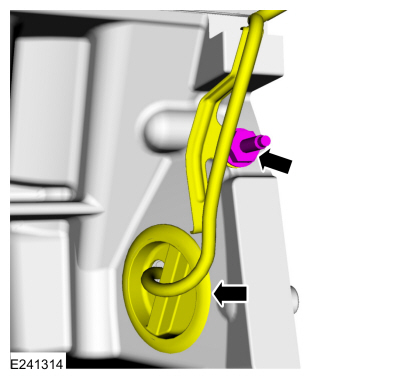
-
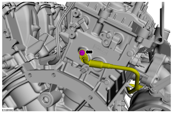
Disconnect the spring lock coupling and then disconnect the high-pressure fuel pump supply line.
Refer to: Spring Lock Couplings (310-00 Fuel System - General Information - 3.5L EcoBoost (272kW/370PS), General Procedures).
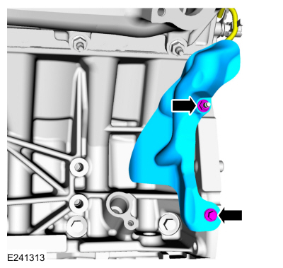
-
Disconnect the high-pressure fuel pump to fuel rail
high-pressure fuel tube flare nuts, then remove and discard the
high-pressure fuel pump to fuel rail high-pressure fuel tube.
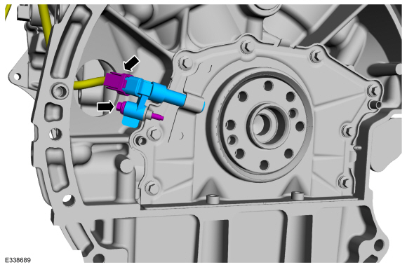
-
Remove and discard the high-pressure fuel pump bolts by
alternately loosening the bolts one complete revolution at a time, then
remove the high-pressure fuel pump.
-
Remove and discard the high-pressure fuel pump O-ring seal.
-
Remove and visually inspect the high pressure fuel pump gasket. Discard if necessary.
-
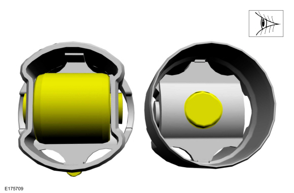
Remove the high-pressure fuel pump roller tappet.
-
Inspect the high-pressure fuel pump roller tappet. If any
flat spots or scoring are found, especially in the indicated areas, then
inspect the high-pressure fuel pump and the high-pressure fuel pump
roller tappet drive lobe. Install new components as needed.
-
Remove any dirt or foreign material from the high-pressure fuel pump bolt holes.
-
-
Disconnect the MAPT electrical connector.
-
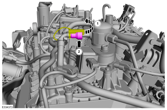
Follow directions to release the quick release coupling type 5.
Refer to: Quick Release Coupling (310-00 Fuel System - General Information - 3.5L EcoBoost (272kW/370PS), General Procedures).
-
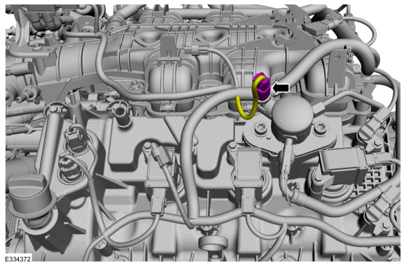
Lift the EVAP purge valve off of the intake manifold mounting tab.
-
Remove the PCV tube.
Refer to: Spring Lock Couplings (310-00 Fuel System - General Information - 3.5L EcoBoost (272kW/370PS), General Procedures).
-
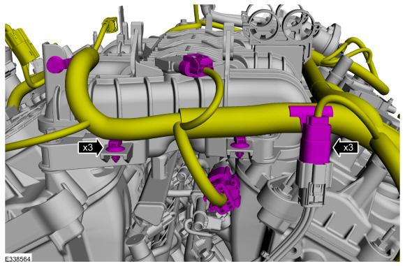
Disconnect the electrical connector and pin-type retainers.
-
Disconnect the RH
TC electrical connector.
-
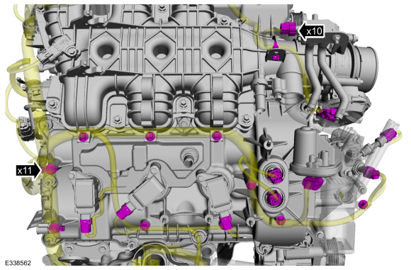
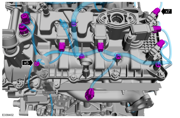
Disconnect the electrical connectors and detach pin-type retainers.
-
-
Disconnect the cylinder head temperature sensor and camphaser electrical connectors.
-
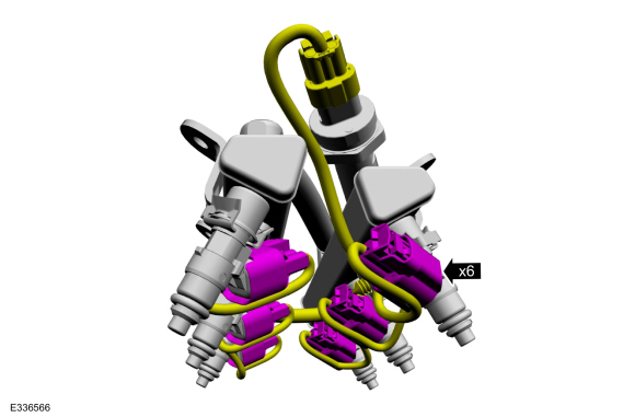
Disconnect the fuel injector electrical connectors.
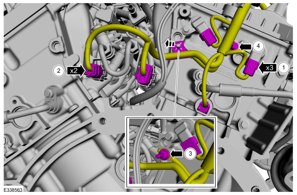
-
Remove the wire retainer from the stud and remove the stud.
-
Detach the pin-type retainer.
-
Disconnect the intake , knock and port injection fuel rail electrical connectors. Detach the pin-type retainers.
-
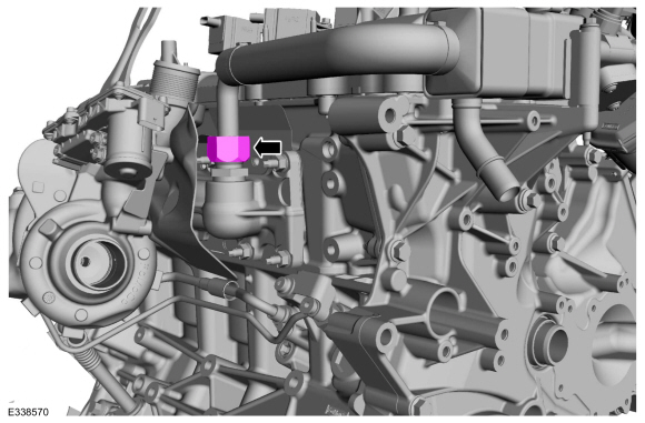
Remove the end nut from the EGR tube to exhaust manifold connector.
-
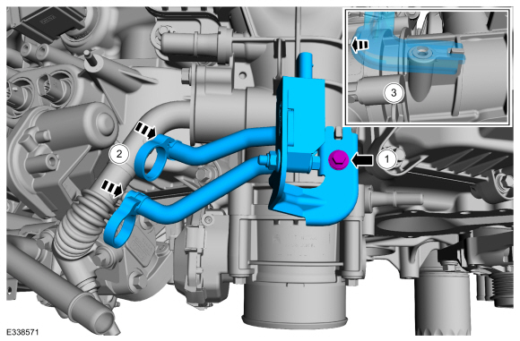
-
Remove the EGR cooler bracket from the intake.
-
Remove the bolts and the EGR cooler.
-
Remove and discard the EGR to exhaust manifold connector.
-
Remove the nut, bolt and the generator.
-
Remove the generator stud bolt.
-
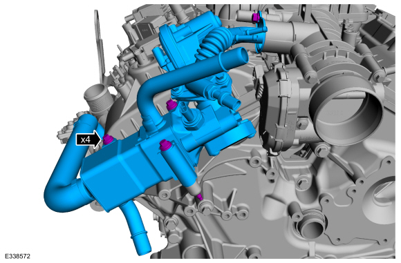
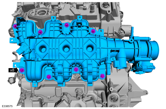
Remove the pin-type retainers and wire harness from the intake manifold.
-
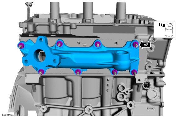
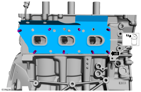
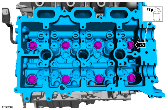
Remove the bolts and the intake manifold.
-
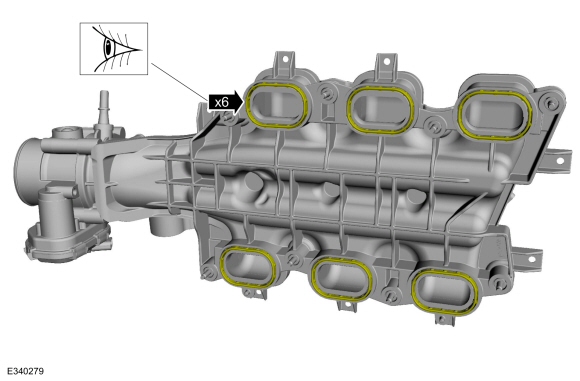
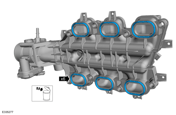
Inspect the gaskets for nicks, cuts and abrasions. If these conditions are not present, the gasket may be re-used.
-
NOTE:
This step only necessary if there are any nicks, cuts or abrasions present.
-
Clean and inspect all of the sealing surfaces of the cylinder heads and the intake manifold.
-
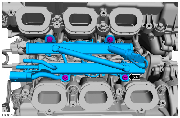
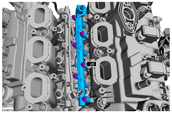
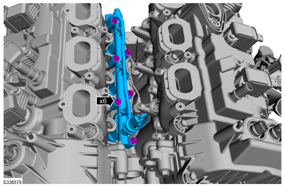
Remove the bolts and the fuel rails.
-
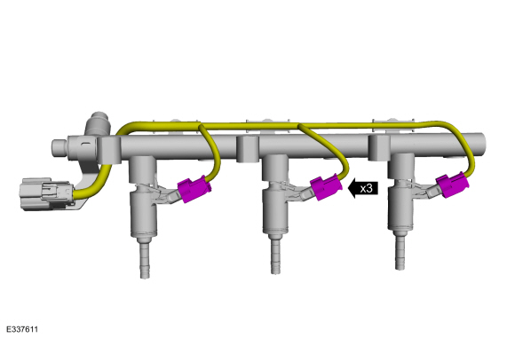
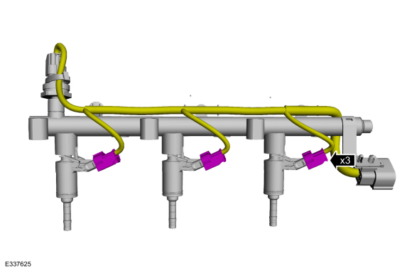
Disconnect the fuel injector electrical connectors.
-
-
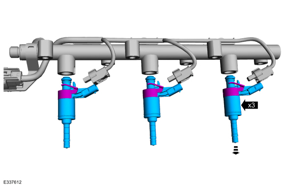
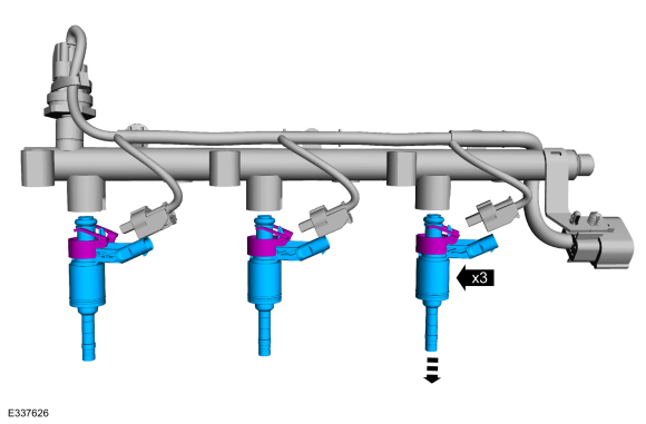
Remove the fuel injector retaining clips.
-
Remove the fuel injectors from the fuel rail.
-
Remove and discard all of the fuel injector O-ring seals.
-
Remove and discard the fuel rail-to-fuel rail high-pressure fuel tube.
-
NOTICE:
Pull out the fuel rails in the direction of the fuel injector axis or damage may occur to the fuel injectors.
NOTE:
Should any of the fuel injectors remain in the cylinder
head, then the injector electrical connectors will need to be
disconnected as the fuel rail is being removed.
-
Use compressed air to remove any dirt or foreign
material from the cylinder head, block and general surrounding area of
the fuel rail and the fuel injectors.
-
Remove the LH fuel rail retaining bolts and then remove the fuel rail.
-
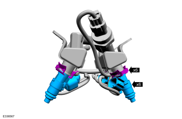
Disconnect the fuel injector electrical connectors.
-
-
Release the fuel injector retaining clips.
-
Remove the fuel injectors from the fuel rail.
-
Remove and discard the clips from all of the fuel injectors
including any injectors that have remained in the cylinder head.
-
-
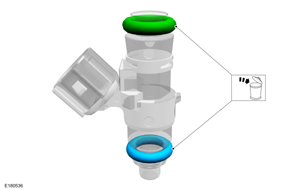
Remove and discard the fuel injector O-ring seals.
-
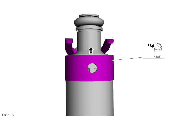
NOTICE:
Use care when removing the lower Teflon® seals, not to scratch, nick or gouge the fuel injectors.
NOTICE:
Do not attempt to cut the lower Teflon® seal without
first pulling it away from the fuel injector or damage to the injector
may occur.
-
Pull the lower Teflon® seal away from the injector.
-
Carefully cut and discard the lower fuel injector Teflon® seals.
-
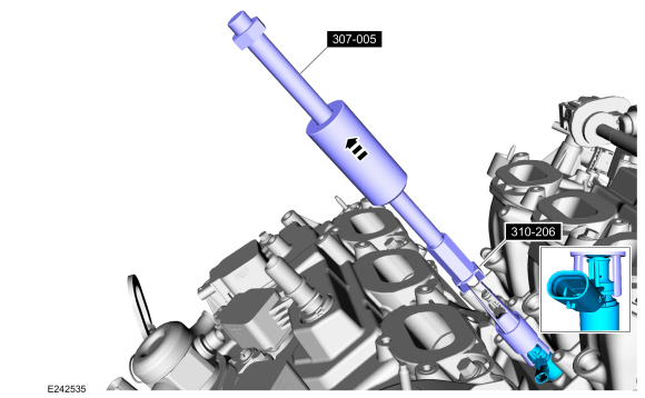
NOTICE:
Use minimal force to remove the fuel injectors that
remained in the cylinder head with the Fuel Injector Remover tool or
damage to the fuel injector assembly may occur. Wiggling the injector by
hand to break it loose may allow the injector to be removed by hand.
Using the special tools, remove any of the fuel injectors that remained in the cylinder head.
Use Special Service Tool: 307-005
(T59L-100-B)
Slide Hammer.
, 310-206
Remover, Fuel Injector.
-
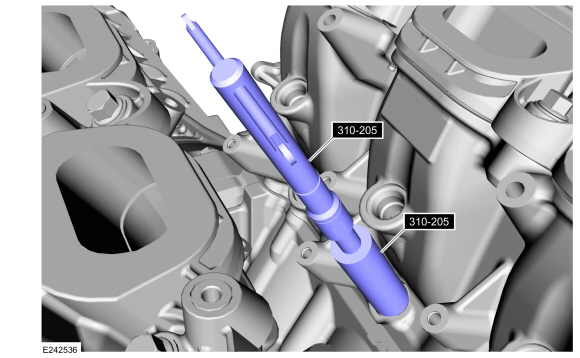
NOTICE:
Make sure to thoroughly clean any residual fuel or
foreign material from the cylinder head, block and the general
surrounding area of the fuel rails and injectors.
NOTICE:
Do not use compressed air to clean the tip of the fuel injector.
NOTICE:
Do not use a brush to clean the tip of the fuel injector.
Using the special tool, clean the cylinder head fuel injector bores.
Use Special Service Tool: 310-205
Fuel Injector Brush.
-
NOTICE:
Pull out the fuel rails in the direction of the fuel injector axis or damage may occur to the fuel injectors.
NOTE:
Should any of the fuel injectors remain in the cylinder
head, then the injector electrical connectors will need to be
disconnected as the fuel rail is being removed.
-
Use compressed air to remove any dirt or foreign
material from the cylinder head, block and general surrounding area of
the fuel rail and the fuel injectors.
-
Remove the RH fuel rail retaining bolts and then remove the fuel rail.
-
Disconnect the fuel injector electrical connectors.
-
-
Release the fuel injector retaining clips.
-
Remove the fuel injectors from the fuel rail.
-
Remove and discard the clips from all of the fuel injectors
including any injectors that have remained in the cylinder head.
-
-
Remove and discard the fuel injector O-ring seals.
-
NOTICE:
Use care when removing the lower Teflon® seals, not to scratch, nick or gouge the fuel injectors.
NOTICE:
Do not attempt to cut the lower Teflon® seal without
first pulling it away from the fuel injector or damage to the injector
may occur.
-
Pull the lower Teflon® seal away from the injector.
-
Carefully cut and discard the lower fuel injector Teflon® seals.
-
NOTICE:
Use minimal force to remove the fuel injectors that
remained in the cylinder head with the Fuel Injector Remover tool or
damage to the fuel injector assembly may occur. Wiggling the injector by
hand to break it loose may allow the injector to be removed by hand.
Using the special tools, remove any of the fuel injectors that remained in the cylinder head.
Use Special Service Tool: 307-005
(T59L-100-B)
Slide Hammer.
, 310-206
Remover, Fuel Injector.
-
NOTICE:
Make sure to thoroughly clean any residual fuel or
foreign material from the cylinder head, block and the general
surrounding area of the fuel rails and injectors.
NOTICE:
Do not use compressed air to clean the tip of the fuel injector.
NOTICE:
Do not use a brush to clean the tip of the fuel injector.
Using the special tool, clean the cylinder head fuel injector bores.
Use Special Service Tool: 310-205
Fuel Injector Brush.
-
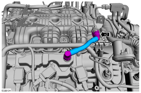
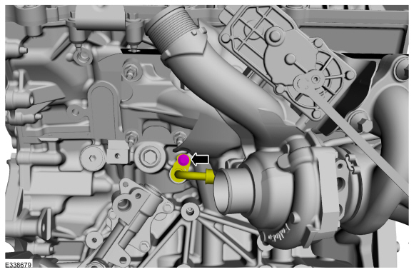
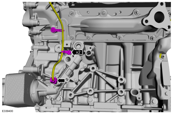
Remove the bolt and separate the RH
TC coolant return tube from the cylinder head.
-
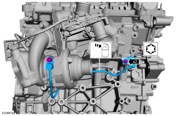
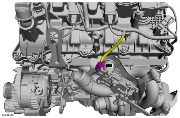
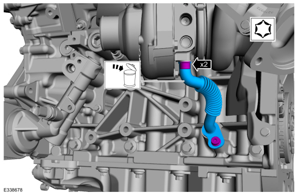
Remove the bolts and theRH
TC oil supply tube then discard the TC oil supply tube.
-
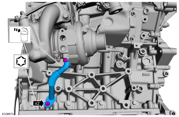
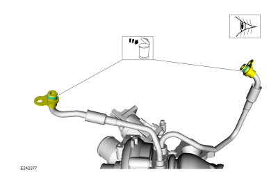
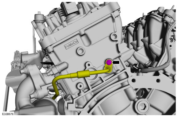
Remove the RH
TC oil return tube bolts, then remove and discard the TC oil return tube.
-
Remove the bolt and separate the RH
TC coolant supply tube the engine block.
-
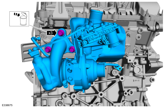
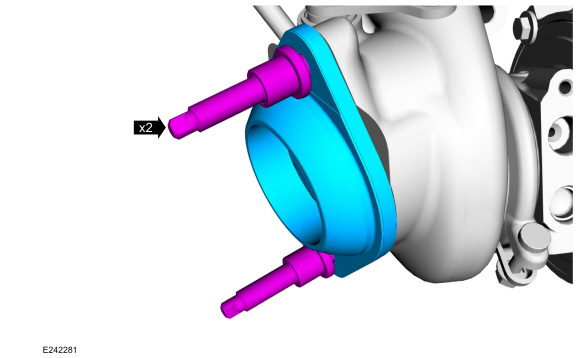
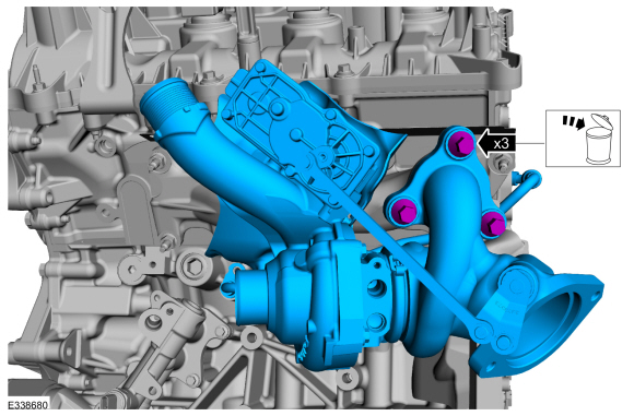
NOTE:
Remove the coolant tubes with the turbocharger. If the 2
piece turbocharger cooling tubes are separated, then the rubber gasket
must be replaced.
Remove the bolts and RH
TC . Discard the bolts.
-
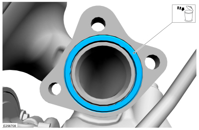
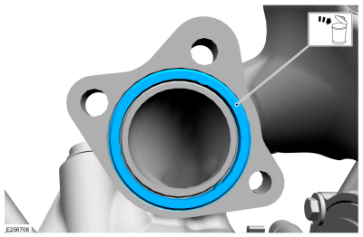
NOTICE:
Use brake cleaner and a nylon brush to clean. Do not use
a metal brush, damage to sealing area will result in leaks.
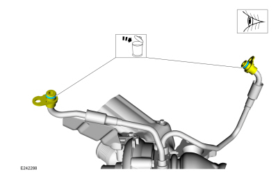
Remove and discard the TC coolant supply and the TC coolant return tube O-ring seals. Clean the TC
coolant tubes sealing surfaces. Inspect the sealing surfaces for
debris or damage and make sure the retaining bracket is not bent, check
for squareness of the O-ring area. Install new components if necessary.
Material: Motorcraft® Metal Brake Parts Cleaner
/ PM-4-A, PM-4-B, APM-4-C
-
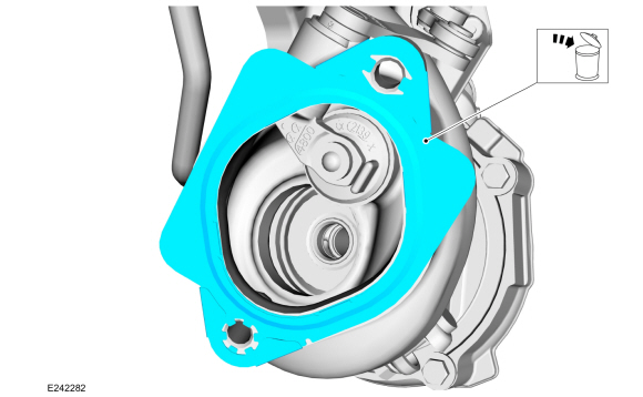
Remove and discard the TC gasket
-
If needed remove the TC exhaust flange stud bolts and the TC exhaust flange.
-
If the flange was removed, remove and discard the turbocharger exhaust flange gasket.
-
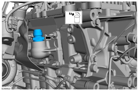
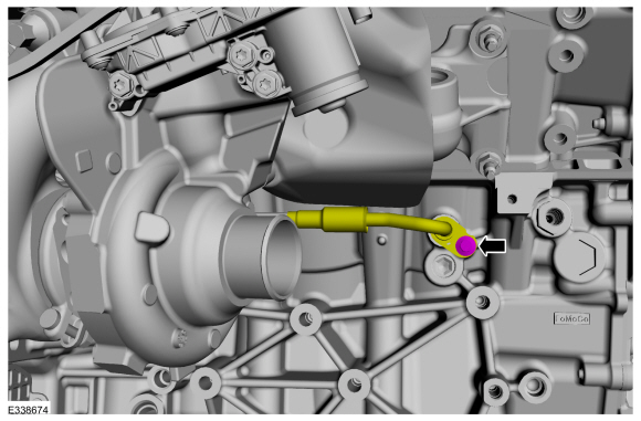
Remove and discard the RH
TC fitting and oil filter assembly from the engine block.
-
Disconnect the LH
TC electrical connector.
-
Remove the bolt and separate the LH
TC coolant return tube from the cylinder head.
-
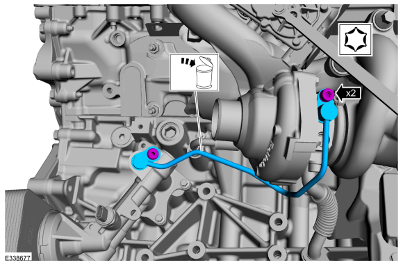
Remove the bolts and the LH oil supply tube then discard the TC oil supply tube.
-
Remove the LH
TC oil return tube bolts, then remove and discard the TC oil return tube.
-
Remove the bolt and separate the LH
TC coolant supply tube the engine block.
-
NOTE:
Remove the coolant tubes with the turbocharger. If the 2
piece turbocharger cooling tubes are separated, then the rubber gasket
must be replaced.
Remove the bolts and LH
TC . Discard the bolts.
-
NOTICE:
Use brake cleaner and a nylon brush to clean. Do not use
a metal brush, damage to sealing area will result in leaks.
Remove and discard the TC coolant supply and the TC coolant return tube O-ring seals. Clean the TC
coolant tubes sealing surfaces. Inspect the sealing surfaces for
debris or damage and make sure the retaining bracket is not bent, check
for squareness of the O-ring area. Install new components if necessary.
Material: Motorcraft® Metal Brake Parts Cleaner
/ PM-4-A, PM-4-B, APM-4-C
-
Remove and discard the TC gasket
-
If needed remove the TC exhaust flange stud bolts and the TC exhaust flange.
-
If the flange was removed, remove and discard the turbocharger exhaust flange gasket.
-
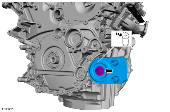
Disconnect the oil pressure electrical connector and detach the pin-type retainers.
-
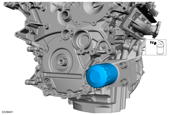
Remove and discard the oil filter.
-
NOTICE:
If metal or aluminum material is present in the oil
cooler, mechanical concerns exist. Failure to correct these concerns may
cause engine failure.
-
Remove the bolt and the oil cooler.
-
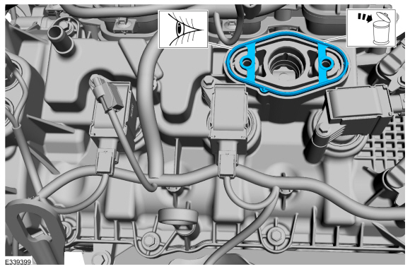
Remove the bolts and the oil filter adapter.
-
Inspect the gasket and replace if necessary.
-
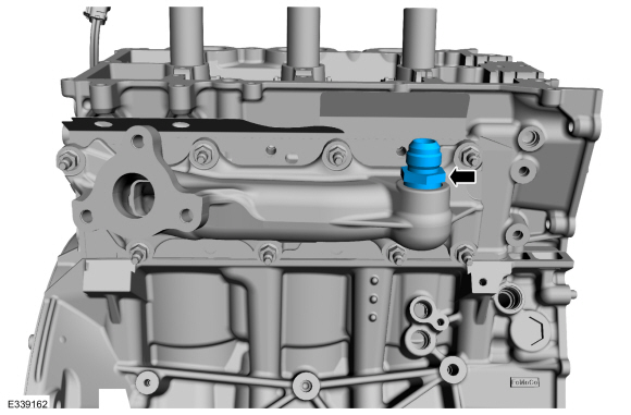
Remove the LH block coolant drain or block heater and allow coolant to drain from the cylinder block.
-
Remove the RH block coolant drain plug and allow coolant to drain from the cylinder block.
-
Remove the bolts and the heat shield.
-
Remove the nut, bolt and the heat shield.
-
-
Detach the wiring harness grommet from the cylinder block.
-
-
Disconnect the CKP sensor electrical connector.
-
Remove the bolt, the CKP sensor electrical connector and position the wiring harness aside.
-
Remove the stud and the ground wire.
-
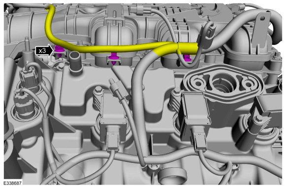
Disconnect the electrical connectors, detach the pin-type retainers and remove the engine wire harness.
-
Remove Special Service Tool: 303-1654
Lift Eyes.
-
Remove Special Service Tool: 303-1654
Lift Eyes.
-
NOTE:
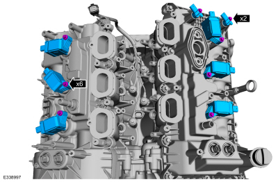
When removing the ignition coil-on-plugs, a slight twisting motion will break the seal and ease removal.
-
Remove the bolts and the ignition coil-on-plugs.
-
Remove the bolts and the CMP sensors.
-
Inspect the coil seals for rips, nicks or tears.
-
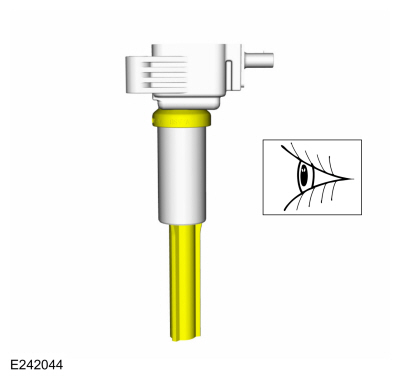
Remove the oil fill pipe and the oil level indicator.
-
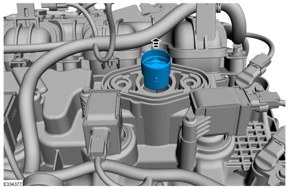
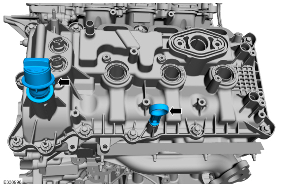
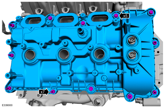
NOTICE:
While removing the valve cover do not apply excessive force to the VCT oil control solenoid or damage may occur.
NOTICE:
If the VCT oil control solenoid sticks to the VCT seal, carefully
wiggle the valve cover until the bond breaks free or damage to the VCT
seal and VCT oil control solenoid may occur.
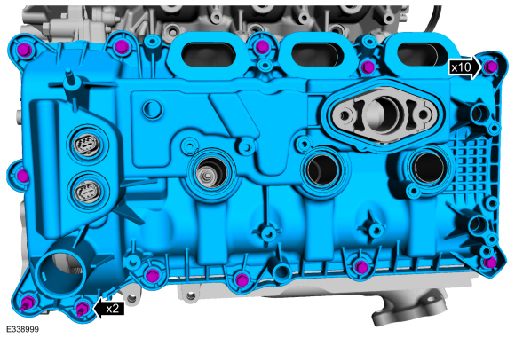
Loosen the fasteners and remove the LH valve cover.
-
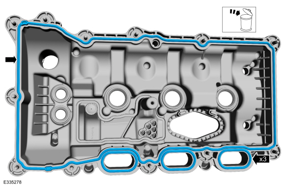
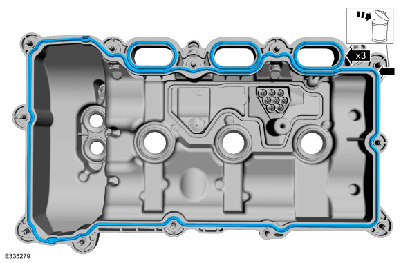
Remove and discard the valve cover and intake port gaskets.
-
NOTICE:
While removing the valve cover do not apply excessive force to the VCT oil control solenoid or damage may occur.
NOTICE:
If the VCT oil control solenoid sticks to the VCT seal, carefully
wiggle the valve cover until the bond breaks free or damage to the VCT
seal and VCT oil control solenoid may occur.
Loosen the fasteners and remove the RH valve cover.
-
Remove and discard the valve cover and intake port gaskets.
-
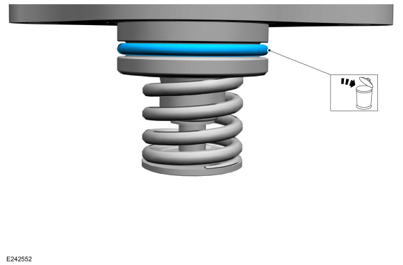
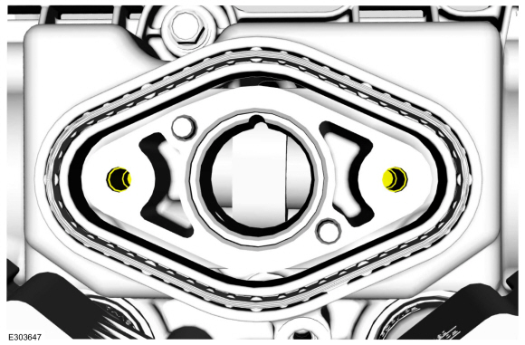
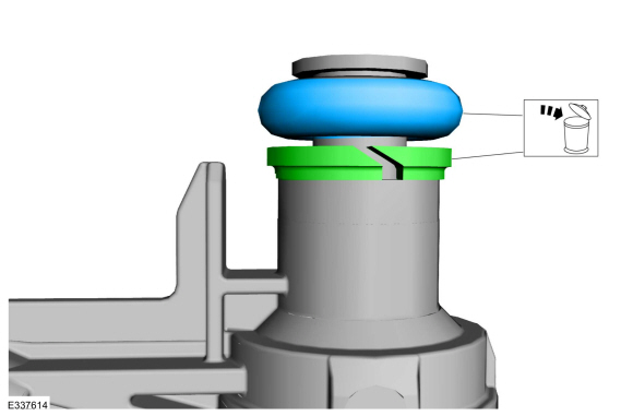
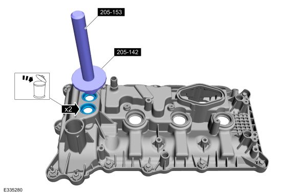
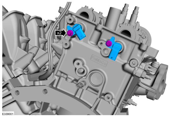
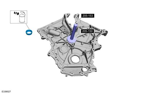
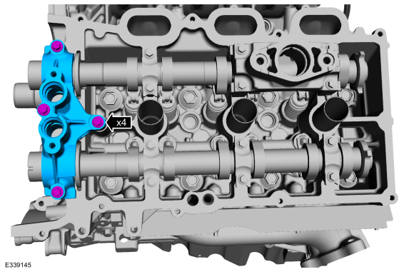
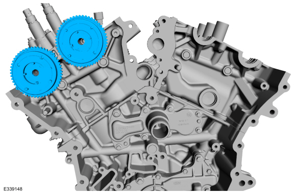
NOTE:
LH shown, RH similar.
NOTE:
Inspect the VCT solenoid seals. Remove any damaged seals.
Using the special tools, remove and discard the seal(s).
Use Special Service Tool: 205-142
(T80T-4000-J)
Installer, Differential Bearing Cone.
, 205-153
(T80T-4000-W)
Handle.
-
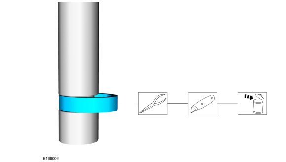
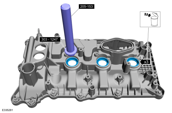
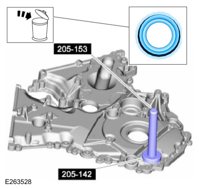
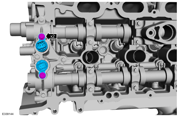
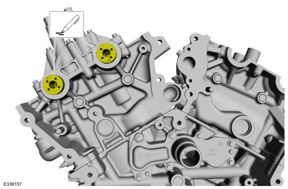
NOTE:
LH shown, RH similar.
NOTE:
Inspect the spark plug tube seals. Remove any damaged seals.
Using the special tools, remove and discard the seal(s).
Use Special Service Tool: 205-153
(T80T-4000-W)
Handle.
, 303-1247
VCT Spark Plug Tube Seal Remover and Installer.
-
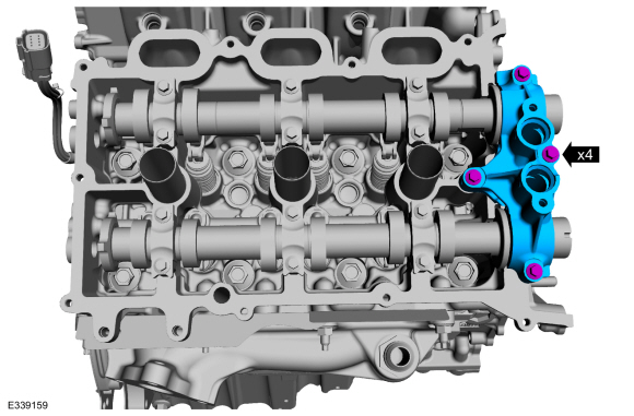
Remove the bolts and the CMP sensors.
-
Remove the cylinder head temperature sensor.
-
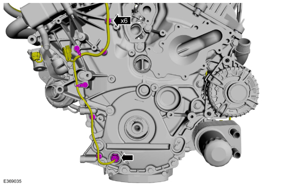
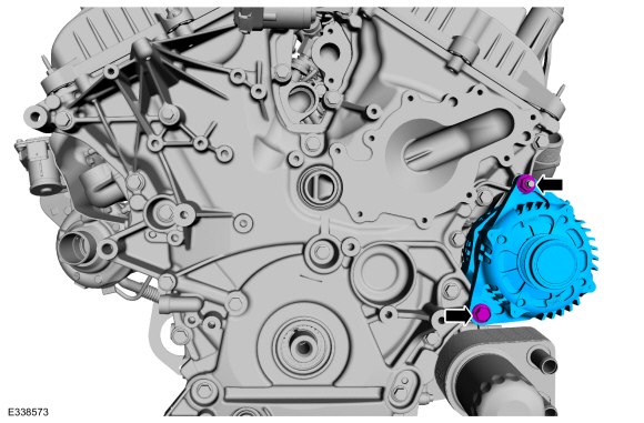
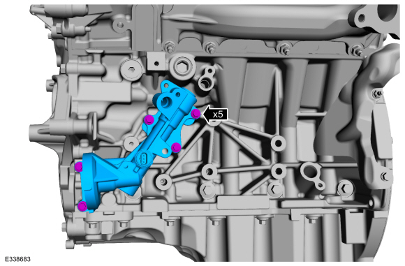
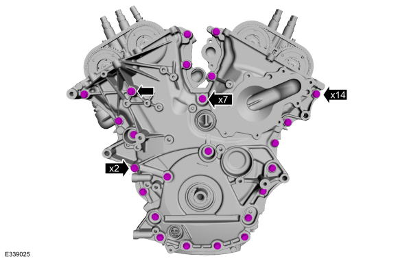
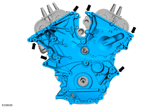
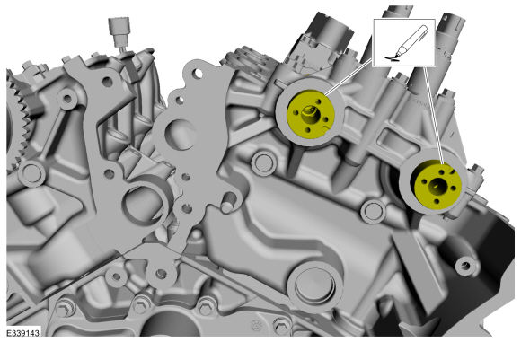
Remove the bolts.
-
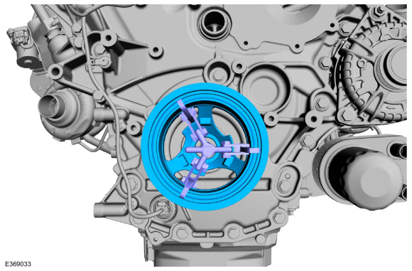
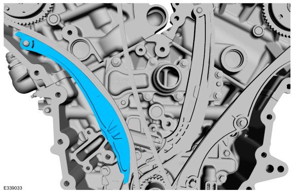
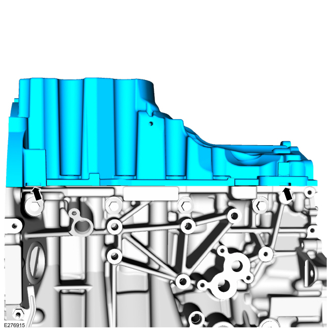
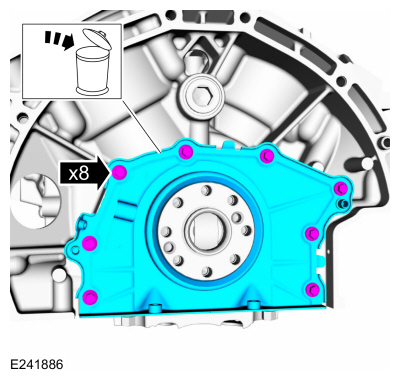
Using a pry tool, locate the 5 pry pads shown and pry the engine front cover loose and remove.
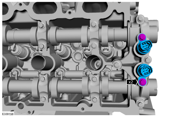
-
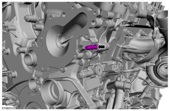
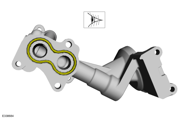
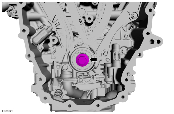
Using the special tools, remove the engine front cover to coolant pipe seal.
Use Special Service Tool: 205-153
(T80T-4000-W)
Handle.
, 205-150
(T80T-4000-S)
Installer, Spindle Bearing.
-
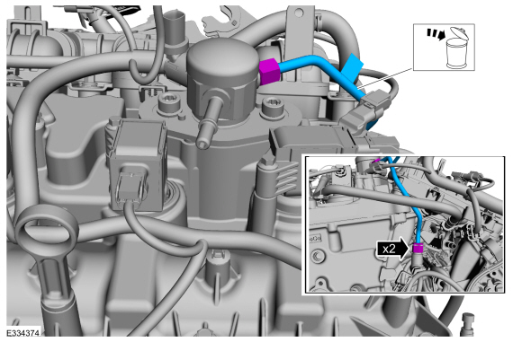
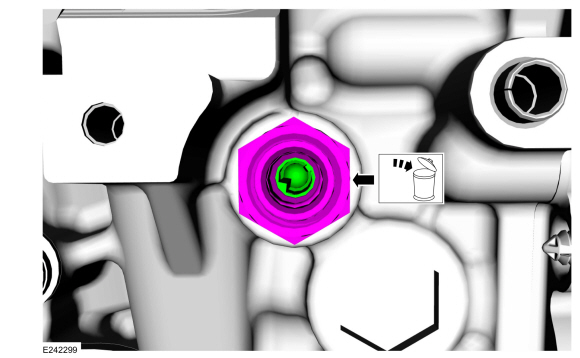
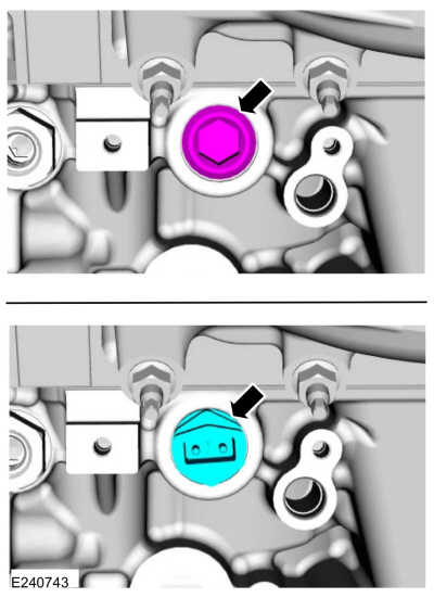
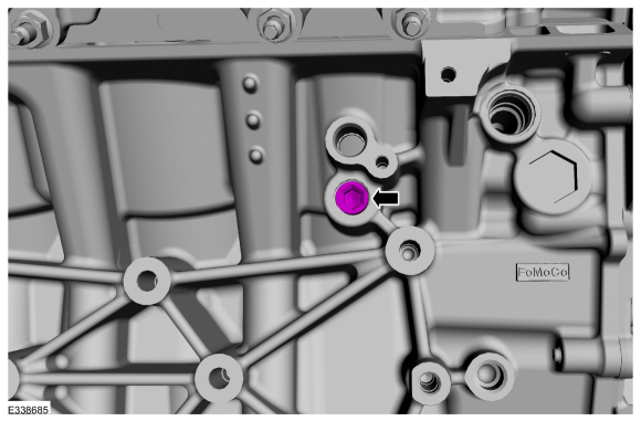
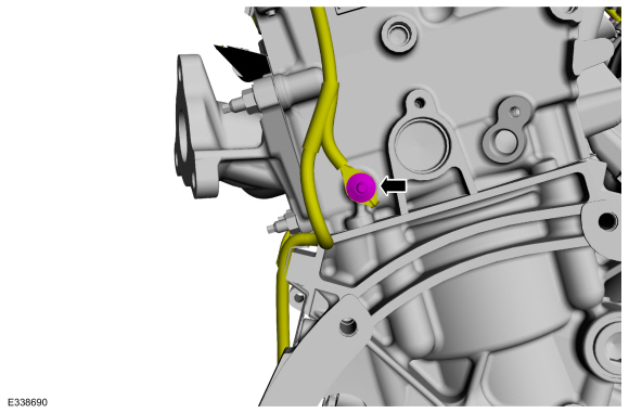
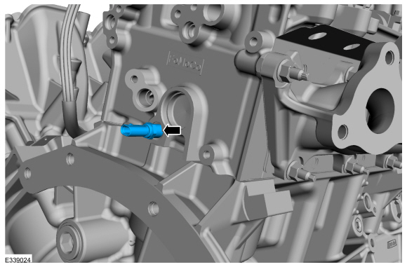
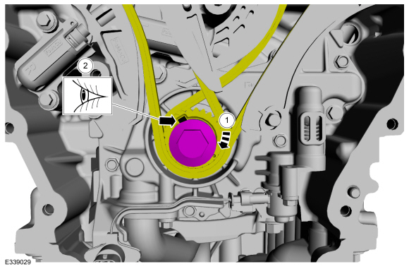
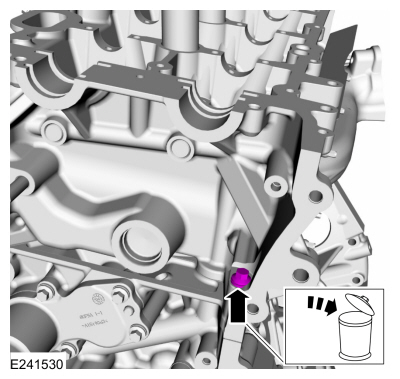
Using the special tools, remove and discard the oil pump electrical connector seal.
Use Special Service Tool: 205-153
(T80T-4000-W)
Handle.
, 205-142
(T80T-4000-J)
Installer, Differential Bearing Cone.
-
-
Clean the prepare the RTV sealing surface.
Refer to: RTV Sealing Surface Cleaning and Preparation (303-00 Engine System - General Information, General Procedures).
-
Install the crankshaft pulley bolt.
-
-
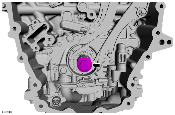
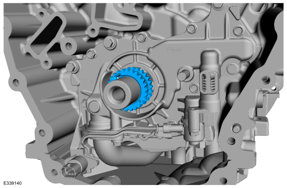
Rotate the crankshaft clockwise.
-
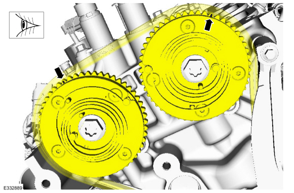
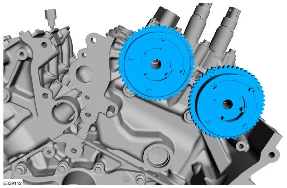
Position the crankshaft sprocket keyway at the 11 o'clock position.
-
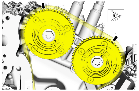
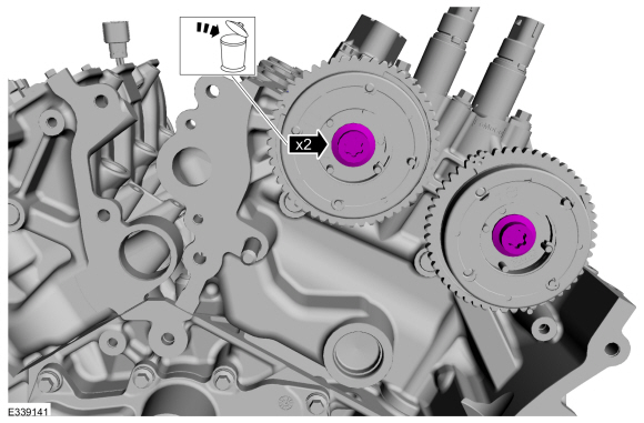
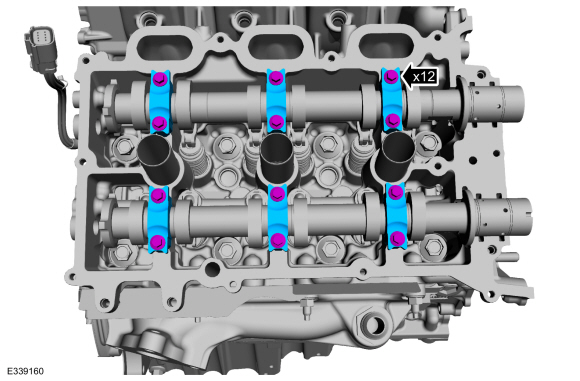
Verify the timing marks on the VCT units are at the positions shown.
-
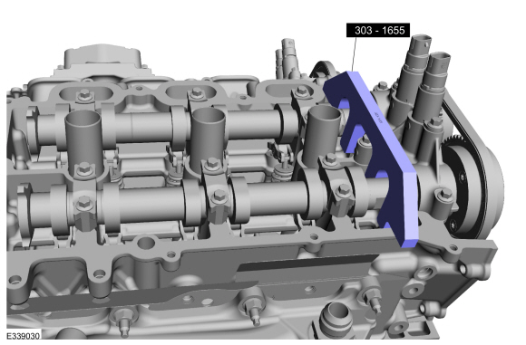
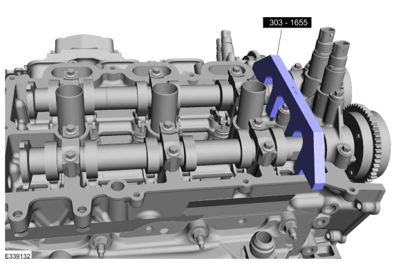
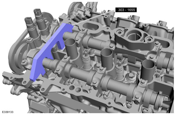
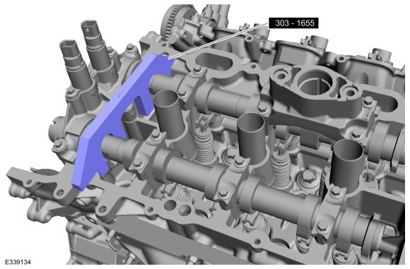
NOTE:
The Camshaft Holding Tool will hold the camshafts in the TDC position.
Install Special Service Tool: 303-1655
Tool, Camshaft Holding.
-
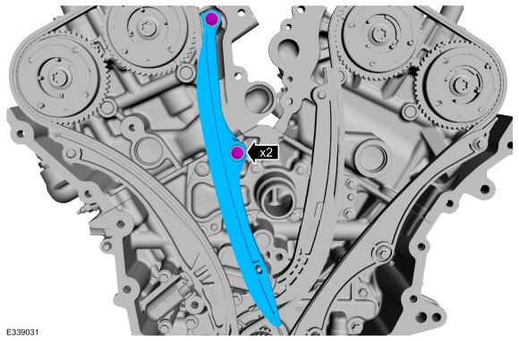
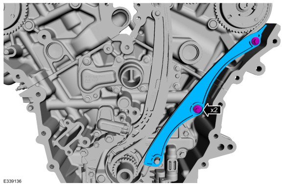
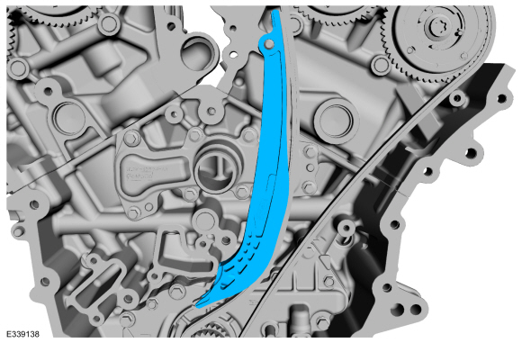
Remove the bolts and the RH timing chain guide.
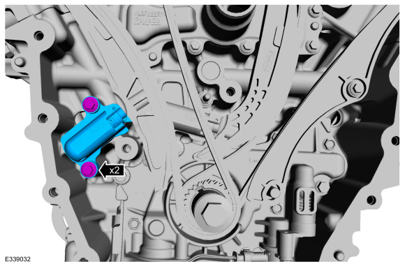
-
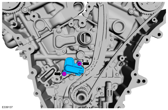
Remove the bolts and the RH timing chain tensioner.
-
Remove the RH timing chain tensioner arm.
-
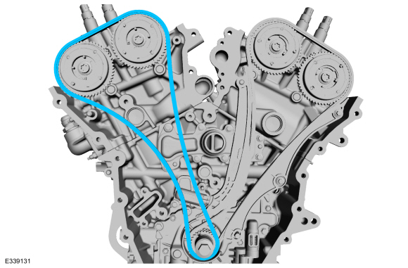
Remove the RH timing chain.
-
NOTE:
The Camshaft Holding Tool will hold the camshafts in the TDC position.
Remove Suggested Tool: 303-1655
Tool, Camshaft Holding.
-
Verify the timing marks on the VCT units are at the 11:30 (intake) and 1:00 o'clock (exhaust) positions.
-
NOTE:
The Camshaft Holding Tool will hold the camshafts in the TDC position.
Install Special Service Tool: 303-1655
Tool, Camshaft Holding.
-
Remove the crankshaft pulley bolt.
-
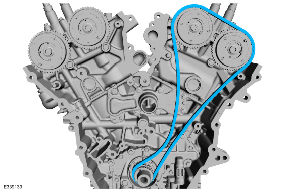
Remove the bolts and the LH timing chain guide.
-
Remove the bolts and the LH timing chain tensioner.
-
Remove the LH timing chain tensioner arm.
-
Remove the LH timing chain.
-
Remove the crankshaft sprocket.
-
Remove and discard the LH
VCT unit bolts.
-
Remove the LH
VCT units.
-
Remove Special Service Tool: 303-1655
Tool, Camshaft Holding.
-
Mark the exhaust and intake camshafts for installation into their original locations.
-
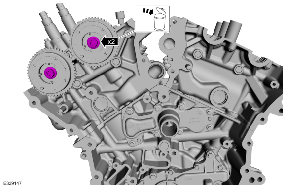
Remove the bolts and the camshaft variable timing assemblies.
-
NOTICE:
The front camshaft bearing mega cap must be removed
first and then the remaining camshaft bearing caps. Failure to follow
this direction may result in damage to the engine.
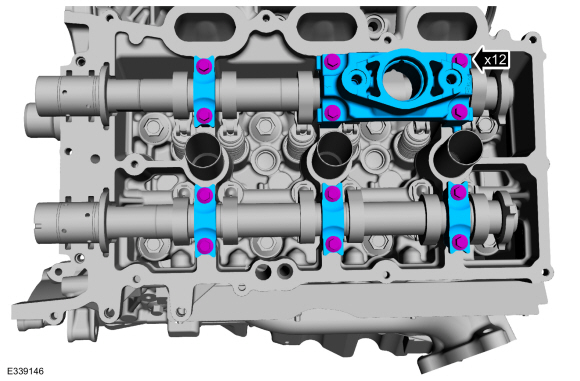
Remove the bolts and the front camshaft bearing mega cap.
-
Remove the bolts and the camshaft bearing caps.
-
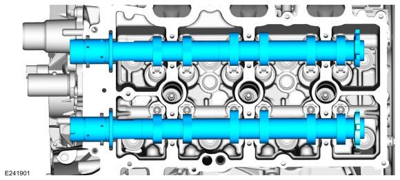
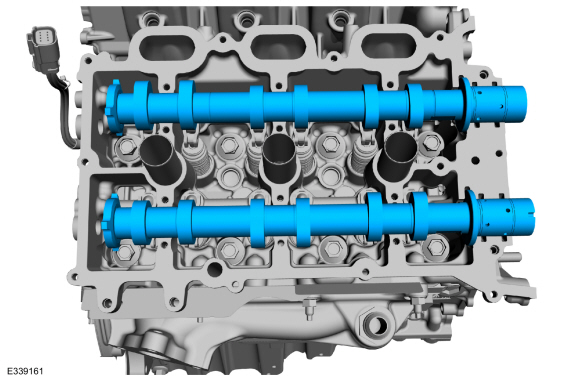
Remove the intake and exhaust camshaft.
-
Remove and discard the RH
VCT unit bolts.
-
Remove the RH
VCT units.
-
Mark the exhaust and intake camshafts for installation into their original locations.
-
Remove the bolts and the camshaft variable timing assemblies.
-
NOTICE:
The front camshaft bearing mega cap must be removed
first and then the remaining camshaft bearing caps. Failure to follow
this direction may result in damage to the engine.
Remove the bolts and the front camshaft bearing mega cap.
-
Remove the bolts and the camshaft bearing caps.
-
Remove the intake and exhaust camshaft.
-
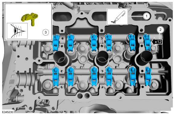
NOTE:
If the components are to be reinstalled, they must be
installed in the same positions. Mark the components for installation
into their original locations.
NOTE:
RH shown, LH similar.
-
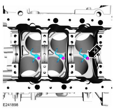
Mark the location of the clipped roller finger followers and hydraulic lash adjuster assemblies before removal.
-
Remove the clipped roller finger followers and hydraulic lash adjuster assemblies.
-
Inspect the clipped roller finger followers and
hydraulic lash adjuster assemblies for damage. If any damage is found,
inspect the camshaft lobes and valves for damage. Replace damaged
components as necessary.
-
Remove the EGR to exhaust manifold connector.
-
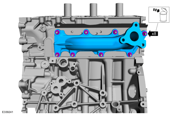
Remove the nuts and the RH exhaust manifold. Discard the nuts.
-
Remove the nuts, the RH exhaust manifold gasket and discard.
-
Remove and discard the RH M6 bolt.
-
NOTICE:
Place clean shop towels over exposed engine cavities.
Carefully remove the towels so foreign material is not dropped into the
engine. Any foreign material (including any material created while
cleaning gasket surfaces) that enters the oil passages or the oil pan,
may cause engine failure.
NOTICE:
Aluminum surfaces are soft and can be scratched easily.
Never place the cylinder head gasket surface, unprotected, on a bench
surface
NOTE:
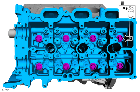
The cylinder head bolts must be discarded and new bolts
must be installed. They are tighten-to-yield designed and cannot be
reused.
-
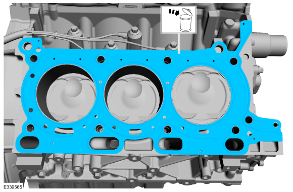
Remove and discard the bolts from the RH cylinder head.
-
Remove the cylinder head.
-
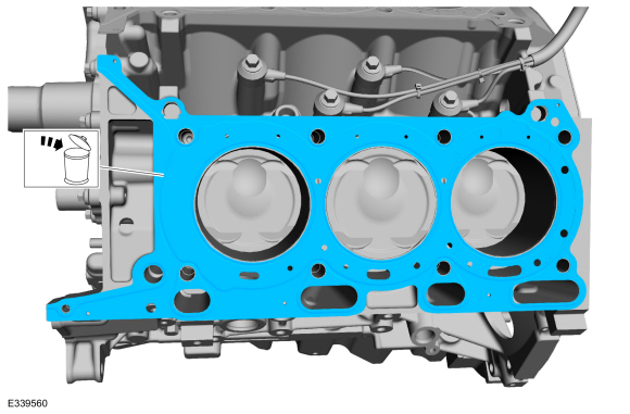
Remove and discard the LH cylinder head gasket.
-
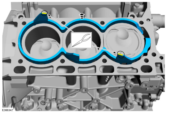
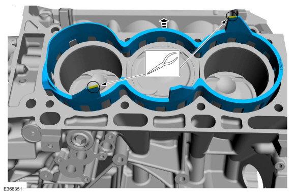
Remove the RH water jacket spacer.
Use the General Equipment: Long Nose Pliers
-
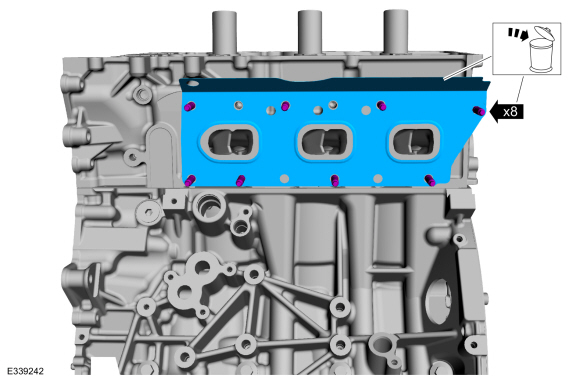
Remove the nuts and the LH exhaust manifold. Discard the nuts.
-
Remove the nuts, the LH exhaust manifold gasket and discard.
-
Remove and discard the LH M6 bolt.
-
NOTICE:
Place clean shop towels over exposed engine cavities.
Carefully remove the towels so foreign material is not dropped into the
engine. Any foreign material (including any material created while
cleaning gasket surfaces) that enters the oil passages or the oil pan,
may cause engine failure.
NOTICE:
Aluminum surfaces are soft and can be scratched easily.
Never place the cylinder head gasket surface, unprotected, on a bench
surface
NOTE:
The cylinder head bolts must be discarded and new bolts
must be installed. They are tighten-to-yield designed and cannot be
reused.
-
Remove and discard the bolts from the LH cylinder head.
-
Remove the cylinder head.
-
Remove and discard the LH cylinder head gasket.
-
NOTICE:
Do not use metal scrapers, wire brushes, power abrasive
discs or other abrasive means to clean the sealing surfaces. These tools
cause scratches and gouges that make leak paths. Use a plastic scraping
tool to remove all traces of the head gasket.
NOTE:
Observe all warnings or cautions and follow all application directions contained on the packaging.
Make sure that the mating faces are clean and free of foreign material.
Material: Motorcraft® Metal Surface Prep Wipes
/ ZC-31-B
Material: Motorcraft® Metal Brake Parts Cleaner
/ PM-4-A, PM-4-B, APM-4-C
-
Remove the LH water jacket spacer.
Use the General Equipment: Long Nose Pliers
-
Support the cylinder head on a bench with the head gasket side up. Check the cylinder head distortion.
Refer to: Cylinder Head Distortion (303-00 Engine System - General Information, General Procedures).
-
Remove the bolts and the KS .
-
Remove the bolts and the channel cover plate.
-
Inspect and replace if necessary.
-
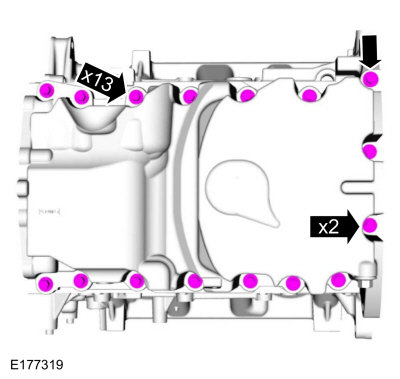
Remove the oil pan bolts.
-
Using a pry tool, locate the pry pads at the LH and RH side of the oil pan and pry the oil pan loose and remove.
-
NOTICE:
Only use a 3M™ Roloc® Bristle Disk (2-in white, part
number 07528) to clean the oil pan and engine front cover. Do not use
metal scrapers, wire brushes or any other power abrasive disk to clean.
These tools cause scratches and gouges that make leak paths.
-
Clean the oil pan using a 3M™ Roloc® Bristle Disk (2-in
white, part number 07528) in a suitable tool turning at the recommended
speed of 15,000 rpm.
Material: Motorcraft® Silicone Gasket Remover
/ ZC-30-A, AZC-30-C
Material: Motorcraft® Metal Surface Prep Wipes
/ ZC-31-B
-
Thoroughly wash the oil pan to remove any foreign
material, including any abrasive particles created during the cleaning
process.
-
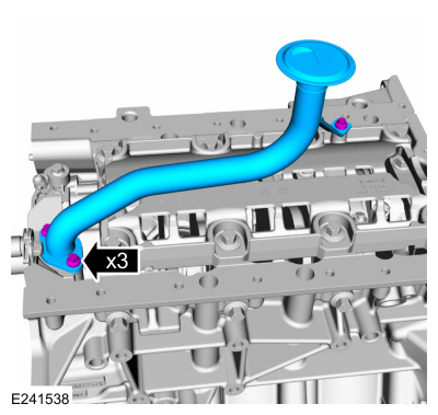
Remove the bolts and the oil pump screen and pickup tube.
-
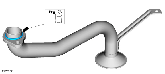
Remove and discard the oil pump screen and pickup tube O-ring seal.
-
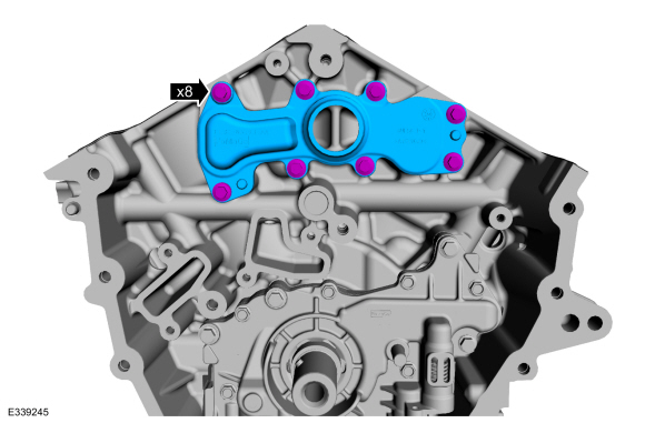
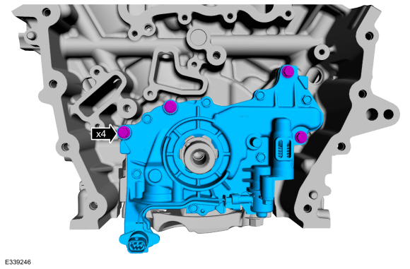
Remove the bolts and the oil pump.
-
-
Remove the bolts and the crankshaft rear seal retainer.
-
Discard the crankshaft rear seal retainer.
-
Inspect and clean the specified component with a abrasive pad.
-
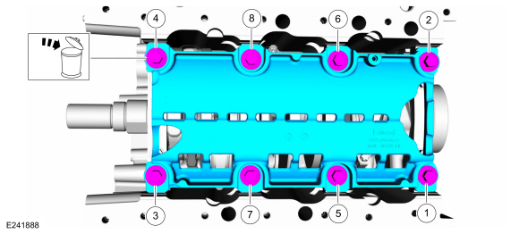
-
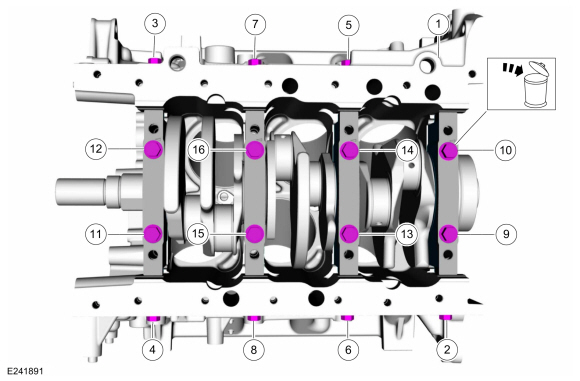
Remove and discard the bolts in sequence shown.
-
Remove the main bearing cap support brace.
-
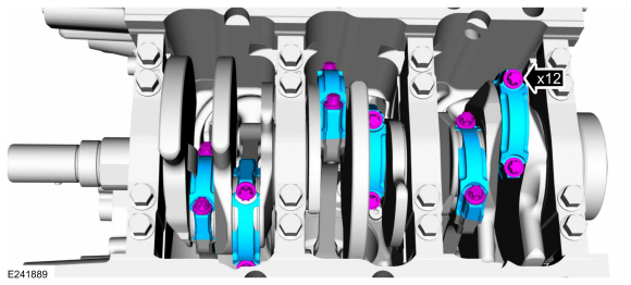
NOTE:
The connecting rod cap bolts are a torque-to-yield
design. The original connecting rod cap bolts will be used when
measuring the connecting rod large end bore during assembly. The
connecting rod cap bolts will be discarded after measurement.
NOTE:
Clearly mark the position and orientation of the
connecting rods, connecting rod caps and connecting rod bearings for
reassembly.
Remove the connecting rod cap bolts and caps.
-
NOTICE:
Do not scratch the cylinder walls or crankshaft journals with the connecting rod while removing the pistons.
Remove the piston/rod assembly from the engine block.
-
Inspect the pistons.
Refer to: Piston Inspection (303-00 Engine System - General Information, General Procedures).
-
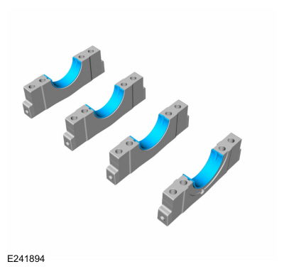
NOTE:
Clearly mark the position and orientation of the main bearing caps for reassembly.
Remove and discard the bolts in sequence shown.
-
NOTE:
If the main bearings are being reused, mark them for correct position and orientation for reassembly.
NOTE:
Note the position of the thrust washer on the outside of the No. 4 rear main bearing cap.
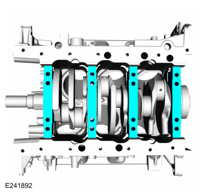
Remove the main bearing caps.
-
Remove the lower crankshaft thrust washer from the back side of the No. 4 rear main bearing cap.
-
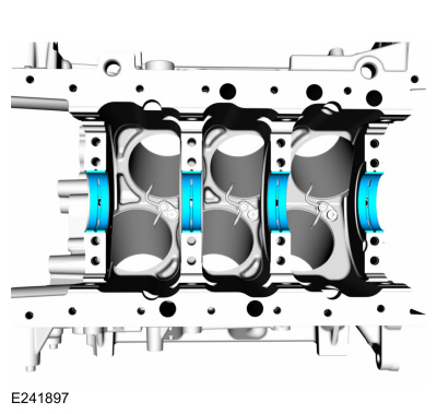
NOTE:
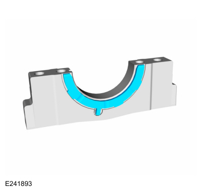
If the main bearings are being reused, mark them for correct position and orientation for reassembly.
Remove the crankshaft main bearings from the main bearing caps.
-
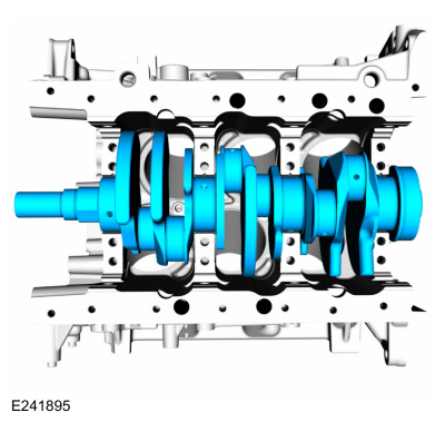
NOTE:
Note the position of the 2 thrust washers on the inside and outside of the rear main bearing bulkhead.
Remove the crankshaft.
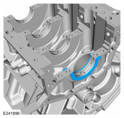
-
Remove the crankshaft thrust bearings from the rear main bearing bulkhead.
-
NOTE:
If the main bearings are being reused, mark them for correct position and orientation for reassembly.
Remove the crankshaft main bearings from the cylinder block.
-
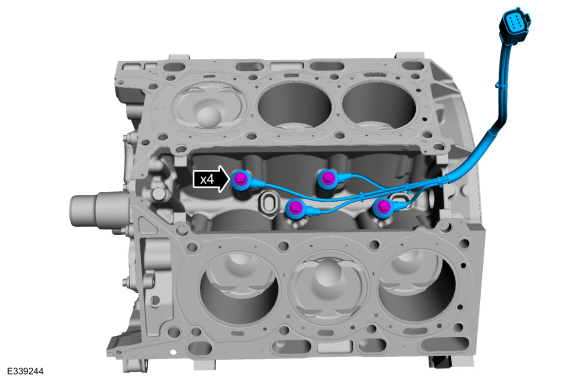
Remove the bolts and the piston cooling jets from the cylinder block.
-
Check the cylinder block distortion.
Refer to: Cylinder Head Distortion (303-00 Engine System - General Information, General Procedures).
-
Clean the prepare the RTV sealing surface.
Refer to: RTV Sealing Surface Cleaning and Preparation (303-00 Engine System - General Information, General Procedures).
Special Tool(s) /
General Equipment
303-1249Valve Spring CompressorTKIT-2006UF-FLMTKIT-2006UF-ROW
303-1418Compressor, Valve SpringTKIT-2008ET-FLMTKIT-2008ET-ROW
303-1567Sizer, Teflon SealTKIT-2010C-FLM
303-300
(T87C-6565-A)
Set, Valve Spring CompressorTKIT-1988-FESTIVAT88C-1000-STTKIT-1988-TRACERTKIT-2009TC-F
303-350
(T89P-6565-A)
Com..
Other information:
Check
NOTE:
Refer to the appropriate Section 303-01 for the specification.
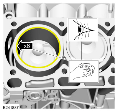
Measure the cylinder bore at the top, middle and bottom
of piston ring travel in 2 directions as indicated. Verify the cylinder
bore is within the wear limit. The difference indicates the cylinder
bore taper. If the cylinder bore taper does not meet specification, bore
the cylinder to the next ..
Special Tool(s) /
General Equipment
Pick Hook
Interior Trim Remover
Removal
Release the clip and remove the sail panel trim panel.
If equipped.
Disconnect the front door tweeter speaker electrical connector.
Use the General Equipment: Interior Trim Remover
Release the clips and remove ..


 Engine. Removal
 Cylinder Head. Disassembly and Assembly of Subassemblies