Lincoln Navigator: Engine - 3.5L EcoBoost (272kW/370PS) / Engine. Removal
Special Tool(s) /
General Equipment
 |
303-1246
Engine Spreader Bar
TKIT-2006UF-FLM
TKIT-2006UF-ROW |
 |
303-1654
Lift Eyes |
 |
307-346
(T97T-7902-A)
Retainer, Torque Converter
TKIT-1998-LM (NavigatoR)
TKIT-1997-F/FLM/LT |
| Floor Crane |
| Oil Drain Equipment |
| Trolley Jack |
| Hose Clamp Remover/Installer |
| Wooden Block |
NOTICE:
The turbocharger compressor vanes can be damaged by even the
smallest particles. When removing any turbocharger or engine air intake
system component, ensure that no debris enters the system. Failure to do
so may result in damage to the turbocharger.
NOTICE:
During the removal or installation of components, cap, tape or
otherwise appropriately protect all openings and tubes/fittings to
prevent the ingress of dirt or other contamination. Remove caps, tape
and other protective materials prior to installation.
-
With the vehicle in NEUTRAL, position it on a hoist.
Refer to: Jacking and Lifting (100-02 Jacking and Lifting, Description and Operation).
-
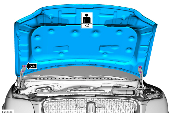
On both sides.
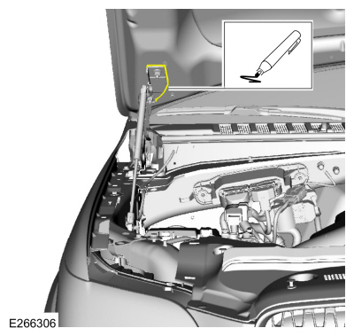
Index-mark the hood hinge location to aid in hood installation.
-
Remove the nuts and the hood.
-
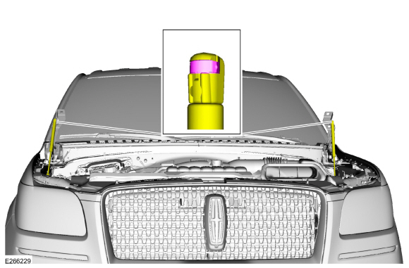
Remove the struts.
-
If equipped.
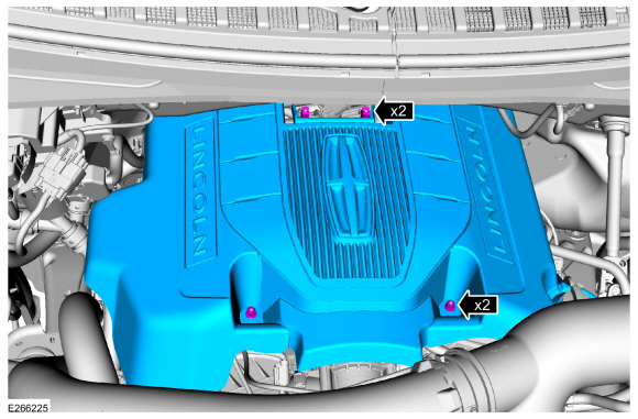
Remove the engine appearance cover retainers, release the
engine appearance cover from the rear retainers and then remove the
engine appearance cover.
-
Release the fuel system pressure.
Refer to: Fuel System Pressure Release (310-00 Fuel System - General
Information - 3.5L EcoBoost (272kW/370PS), General Procedures).
-
Disconnect the battery ground cable.
Refer to: Battery Disconnect and Connect (414-01 Battery, Mounting and Cables, General Procedures).
-
-
Remove the bolts and remove the transmission housing cover.
-
-
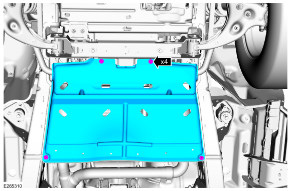
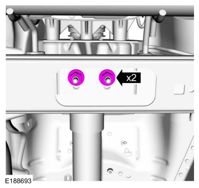
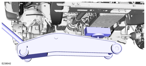
Remove the bolts and the underbody shield.
-
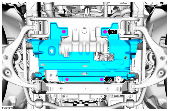
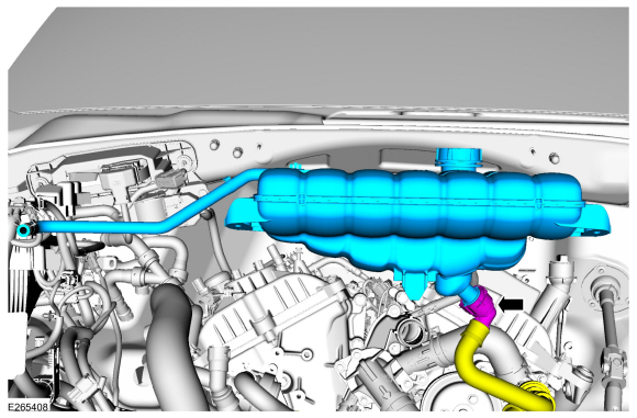
Remove the cooling module.
Refer to: Cooling Module (303-03 Engine Cooling - 3.5L EcoBoost (272kW/370PS), Removal and Installation).
-
-
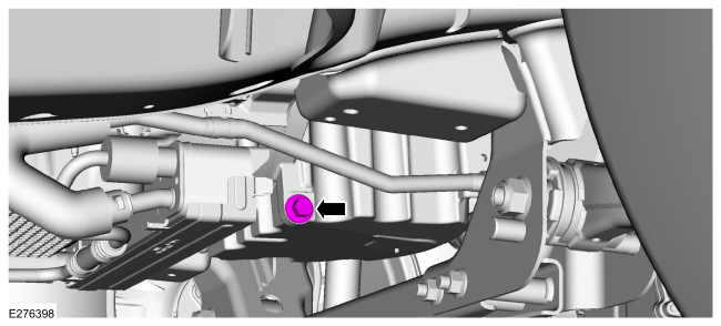
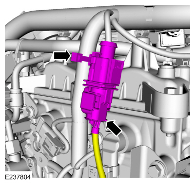
Disconnect the crankcase pressure sensor electrical connector.
-
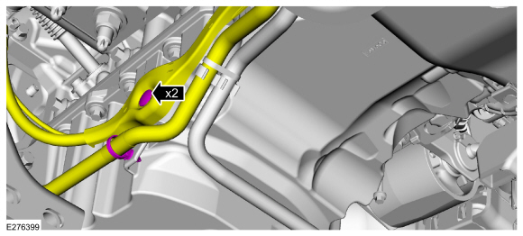
Disconnect the PCV tube quick release couplings and remove the tube.
Refer to: Quick Release Coupling (310-00 Fuel System - General Information - 3.5L EcoBoost (272kW/370PS), General Procedures).
-
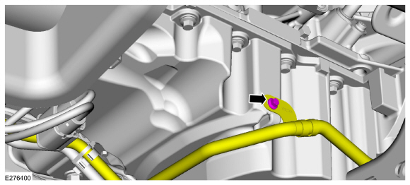
Remove the CAC intake pipe.
Refer to: Charge Air Cooler (CAC) Intake Pipe (303-12 Intake Air
Distribution and Filtering - 3.5L EcoBoost (272kW/370PS), Removal and
Installation).
-
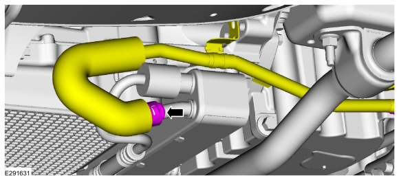
Remove the CAC outlet pipe.
Refer to: Charge Air Cooler (CAC) Outlet Pipe (303-12 Intake Air
Distribution and Filtering - 3.5L EcoBoost (272kW/370PS), Removal and
Installation).
-
If equipped
-
Disconnect the block heater electrical connector and the wire harness retainer.
-
Disconnect the wire harness retainer from the coolant hose.
-
Remove the A/C compressor belt.
Refer to: Air Conditioning (A/C) Compressor Belt (303-05 Accessory
Drive - 3.5L EcoBoost (272kW/370PS), Removal and Installation).
-
NOTICE:
Make sure that all openings are sealed.
-
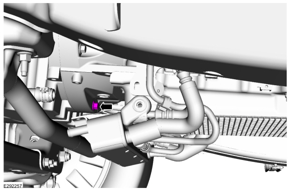
Remove the nut and disconnect the A/C compressor inlet line.
-
Remove and discard the O-ring seal.
-
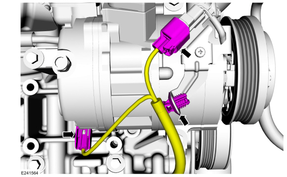
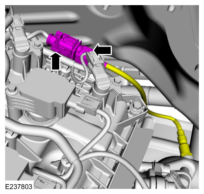
Disconnect the A/C pressure transducer electrical connector.
-
NOTICE:
Make sure to cover any open ports to prevent debris from entering the system.
Remove the A/C compressor inlet and outlet line retainers and disconnect the fittings. Remove and discard the O-ring seals.
-
Disconnect the A/C compressor electrical connectors and wire harness retainer.
-
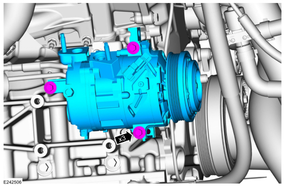
Remove the bolts and the A/C compressor.
-
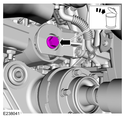
Remove the oil pan plug and drain the engine oil.
Use the General Equipment: Oil Drain Equipment
Torque:
20 lb.ft (27 Nm)
-
Remove the pin-type retainers. Position the wiring harness and transmission tube from the oil pan.
-
Remove the bolt and position aside the transmission cooler tube.
-
NOTE:
Be prepared to collect escaping fluids.
Release the quick connect coupling and disconnect the coolant hose from the transmission fluid cooler.
-
Remove the transmission cooler bolts.
-
NOTE:
Be prepared to collect escaping fluids.
-
Release the clamp and disconnect the coolant hose.
-
Position the transmission fluid cooler aside.
-
Remove the nut and position out the transmission cooler tube bracket. Position out the engine wiring harness.
-
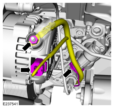
Disconnect the generator wiring harness from the engine front cover.
-
-
Position back the boot and remove the generator nut.
-
Disconnect the electrical connector and the wire harness retainer.
-
Remove the intake manifold.
Refer to: Intake Manifold (303-01 Engine - 3.5L EcoBoost (272kW/370PS), Removal and Installation).
-
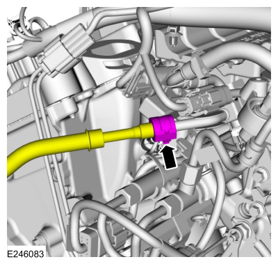
Disconnect the fuel supply tube quick release coupling.
Refer to: Quick Release Coupling (310-00 Fuel System - General Information - 3.5L EcoBoost (272kW/370PS), General Procedures).
-
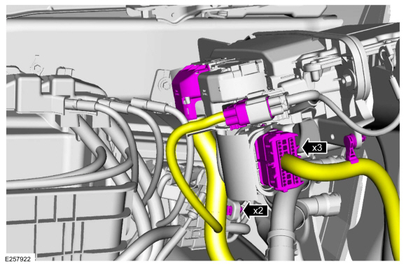
Disconnect the PCM electrical connectors and the wire harness retainers.
-
Detach the transmission wire harness retainers.
-
Disconnect the RH
HO2S electrical connector and the retainer.
-
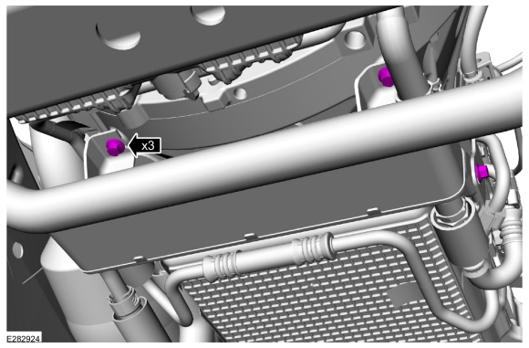
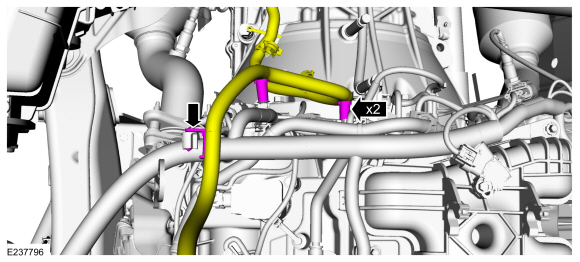
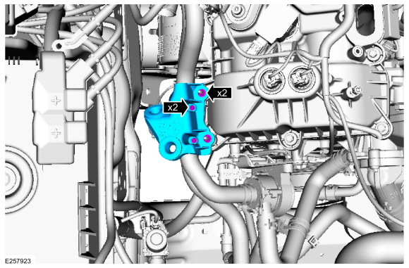
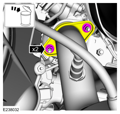
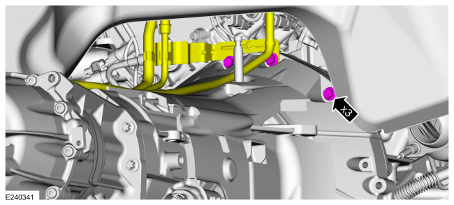
Remove the nuts, pin-type retainers and remove the CAC tube bracket.
-
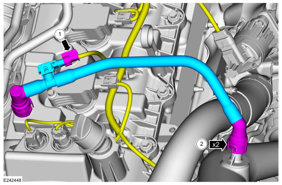
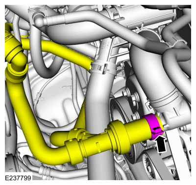
Disconnect and remove the TC bypass valve tube.
Use the General Equipment: Hose Clamp Remover/Installer
-
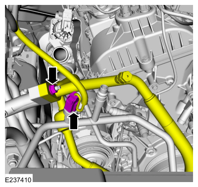
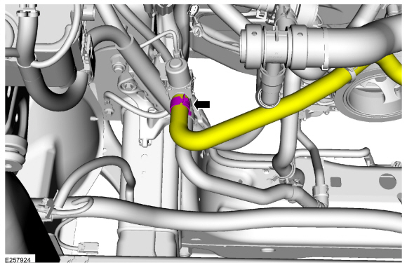
Disconnect the degas bottle hose at the thermostat.
Use the General Equipment: Hose Clamp Remover/Installer
-
Disconnect the coolant hose.
Use the General Equipment: Hose Clamp Remover/Installer
-
Disconnect the coolant hose and remove the degas bottle hose.
Use the General Equipment: Hose Clamp Remover/Installer
-
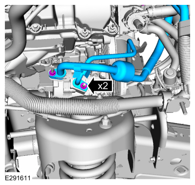
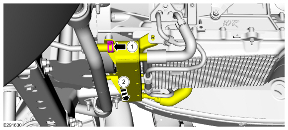
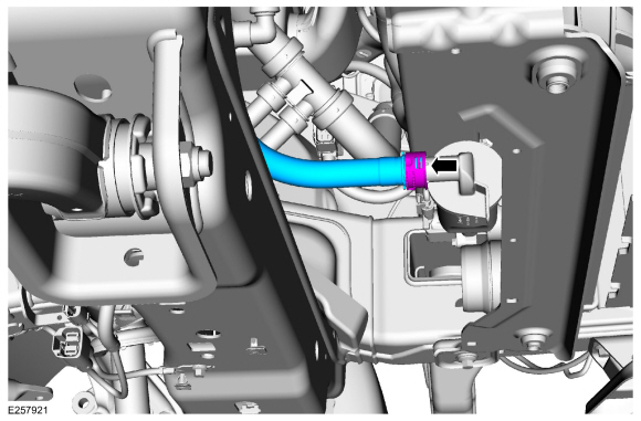
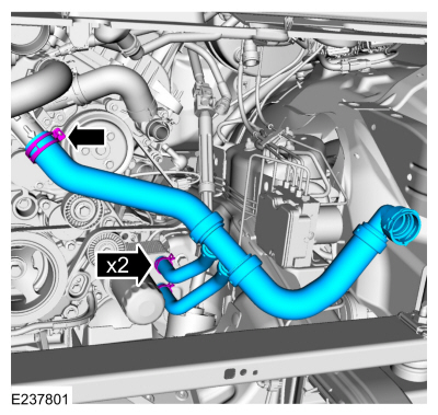
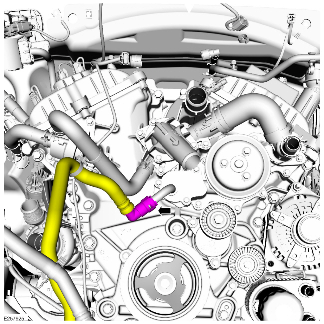
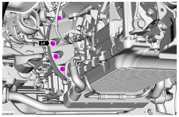
Disconnect the coolant hoses at the oil cooler. Disconnect and remove the radiator hose.
Use the General Equipment: Hose Clamp Remover/Installer
-
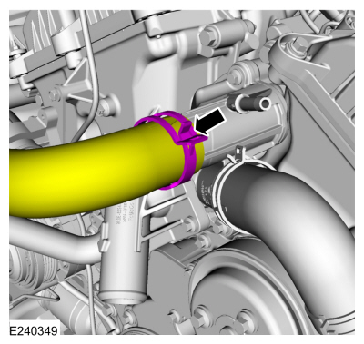
Disconnect the radiator hose from thermostat housing.
Use the General Equipment: Hose Clamp Remover/Installer
-
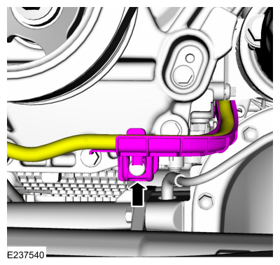
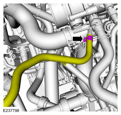
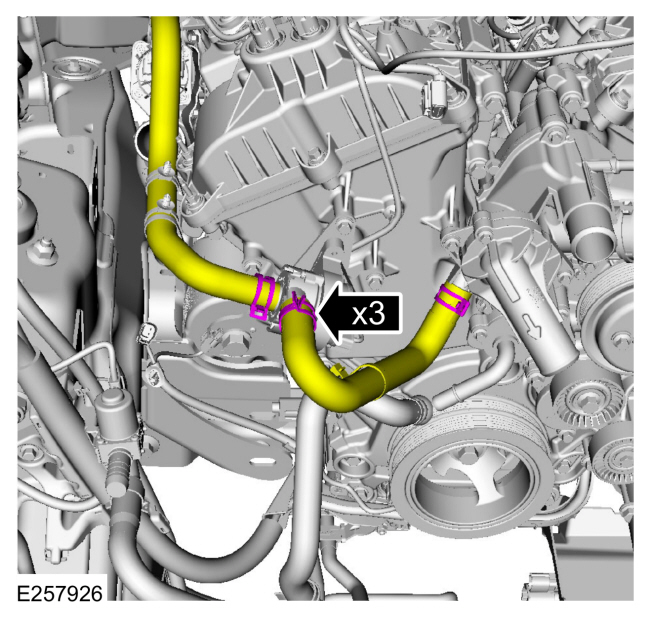
Remove the coolant control valve hose.
Use the General Equipment: Hose Clamp Remover/Installer
-
Disconnect the lower coolant pump hose.
Use the General Equipment: Hose Clamp Remover/Installer
-
Disconnect the cabin heater coolant pump hoses and the thermostat housing hose.
Use the General Equipment: Hose Clamp Remover/Installer
-
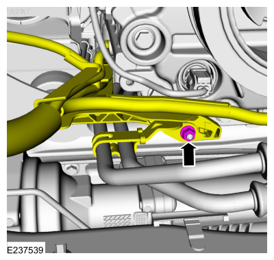
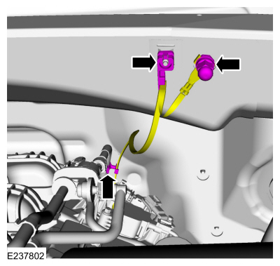
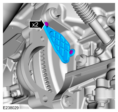
Disconnect the ground strap retainers. Remove the nut and the ground strap.
-
Disconnect the LH
HO2S electrical connector and the retainer.
-
Remove the following items:
-
If equipped.
Remove the front driveshaft.
Refer to: Front Driveshaft (205-01 Driveshaft, Removal and Installation).
-
Remove the starter motor.
Refer to: Starter Motor (303-06 Starting System - 3.5L EcoBoost (272kW/370PS), Removal and Installation).
-
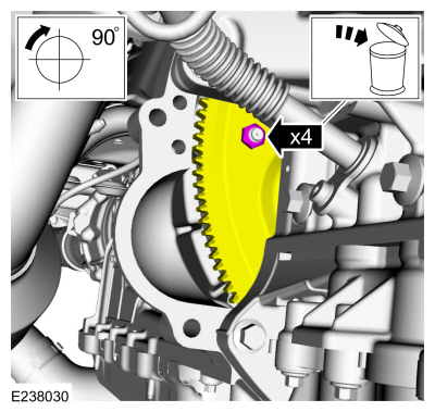
Remove the retainers and the access cover.
-
NOTE:
Index-mark the end of one torque converter stud and the flexplate for installation.
NOTE:
Using the crankshaft pulley bolt, turn the engine clockwise.
Remove and discard the torque converter nuts.
-
NOTE:
Make sure that the mating faces are clean and free of foreign material.
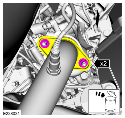
Remove and discard the LH catalytic converter flange nuts.
-
NOTE:
Make sure that the mating faces are clean and free of foreign material.
Remove and discard the RH catalytic converter flange nuts.
-
NOTICE:
Only use hand tools when removing the transmission
mount-to-crossmember nuts or damage to the transmission mount can occur.
Loosen the transmission mount-to-crossmember nuts.
-
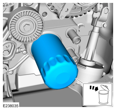
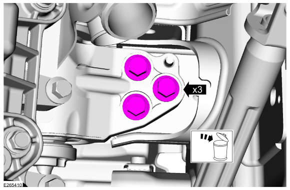
Remove and discard the oil filter.
Use the General Equipment: Oil Drain Equipment
-
NOTE:
Mark the location of the bolts during removal.
Remove the lower bellhousing bolt.
-
NOTE:
Access to fasteners is limited and needs to be done from above.
Remove the upper bellhousing bolts.
-
Remove the LH side bellhousing bolts and the shift cable bracket.
-
Remove the RH side bellhousing bolts.
-
NOTICE:
Only use hand tools when removing the engine mount nuts and studs or damage to the engine mount can occur.
NOTE:
The engine mount studs may come off with the nuts.
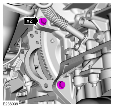
Remove and discard the RH engine mount nuts. Remove the engine mount studs.
-
NOTICE:
Only use hand tools when loosening or tightening the
engine mount through bolts or damage to the engine mount-to-cylinder
block bracket can occur.
Remove and discard the LH engine mount through bolt.
-
NOTICE:
Do not support the transmission by the fluid pan,
failure to follow instruction may result in serious damage to the
transmission.
Support the bellhousing of the transmission with a suitable floor jack and a block of wood.
Use the General Equipment: Trolley Jack
Use the General Equipment: Wooden Block
-
NOTICE:
Only use hand tools when loosening or tightening the
engine mount-to-frame bolts or damage to the engine mount-to-frame nut
plate can occur.
NOTE:
Leave the LH engine mount in place.
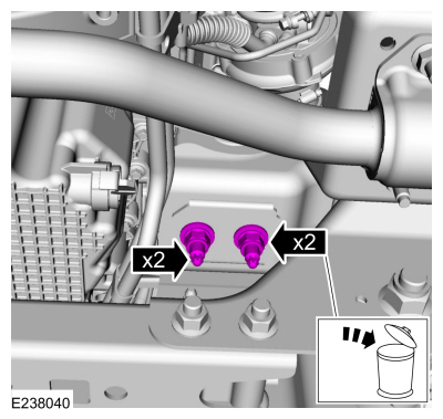
Remove and discard the LH engine mount bolts.
-
Remove the right rear ignition coil.
Refer to: Ignition Coil-On-Plug (303-07 Engine Ignition - 3.5L EcoBoost (272kW/370PS), Removal and Installation).
-
NOTE:
The use of a ratchet strap may be needed to level the engine.
NOTE:
Use a commercially available quick link on the chain to minimize the spread of the chain.
-
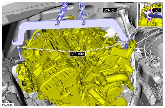
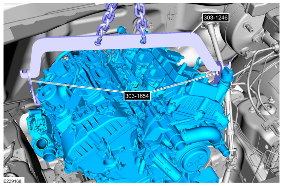
Install the engine spreader bar, lift eyes and the floor crane.
Use Special Service Tool: 303-1246
Engine Spreader Bar.
, 303-1654
Lift Eyes.
Use the General Equipment: Floor Crane
Torque:
18 lb.ft (25 Nm)
-
Using the floor crane, lift eyes and the engine spreader bar, lift the engine.
-
Remove the LH engine mount.
-
Disconnect and position aside the generator wiring harness from the engine.
-
Using the floor crane, lift eyes and the engine spreader bar, remove the engine.
Use Special Service Tool: 303-1246
Engine Spreader Bar.
, 303-1654
Lift Eyes.
Use the General Equipment: Floor Crane
-
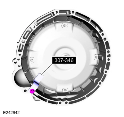
Use Special Service Tool: 307-346
(T97T-7902-A)
Retainer, Torque Converter.
Removal
NOTICE:
During engine repair procedures, cleanliness is extremely
important. Any foreign material, including any material created while
cleaning gasket surfaces, that enters the oil passages, coolant passages
or the oil pan, can cause engine failure...
Special Tool(s) /
General Equipment
205-142
(T80T-4000-J)
Installer, Differential Bearing Cone
205-150
(T80T-4000-S)
Installer, Spindle Bearing
205-153
(T80T-4000-W)
Handle
303-1246Engine Spreader BarTKIT-2006UF-FLMTKIT-2006UF-ROW
303-1247VCT Spark Plug Tube Seal Remover and InstallerTKIT-2006UF-FLMTKIT-2006UF-ROW
303-1..
Other information:
Special Tool(s) /
General Equipment
6.5 mm Drill Bit
11 mm Drill Bit
Rivet Gun
Self-Piercing Rivet (SPR) Remover/Installer
Belt Sander
Hot Air Gun
8 mm Drill Bit
Locking Pliers
Materials
Name
Specification
Metal Bonding AdhesiveTA-1, TA-1-B, 3M™ 08115, LORD Fusor® 108B, Henkel Teroson EP 5055
-
..
Removal
NOTE:
LH side shown, RH side similar.
NOTE:
Removal steps in this procedure may contain installation details.
Aft rear door glass run and bracket
Remove the rear door trim panel.
Refer to: Rear Door Trim Panel (501-05 Interior Trim and Ornamentation, Removal and Installation).
Remove the watershield.
..
 Variable Camshaft Timing (VCT) Unit. Removal and Installation
 Engine. Disassembly