Lincoln Navigator: Engine - 3.5L EcoBoost (272kW/370PS) / Engine. Installation
Special Tool(s) /
General Equipment
 |
303-1246
Engine Spreader Bar
TKIT-2006UF-FLM
TKIT-2006UF-ROW |
 |
303-1654
Lift Eyes |
 |
307-346
(T97T-7902-A)
Retainer, Torque Converter
TKIT-1998-LM (NavigatoR)
TKIT-1997-F/FLM/LT |
| Floor Crane |
| Trolley Jack |
| Hose Clamp Remover/Installer |
| Wooden Block |
Materials
| Name |
Specification |
Motorcraft® Multi-Purpose Grease Spray
XL-5-A |
ESB-M1C93-B
|
Motorcraft® Threadlock 262
TA-26 |
WSK-M2G351-A6
|
NOTICE:
During the removal or installation of components, cap, tape or
otherwise appropriately protect all openings and tubes/fittings to
prevent the ingress of dirt or other contamination. Remove caps, tape
and other protective materials prior to installation.
-
Inspect the TC or engine air intake system components and clean, if necessary.
-
-
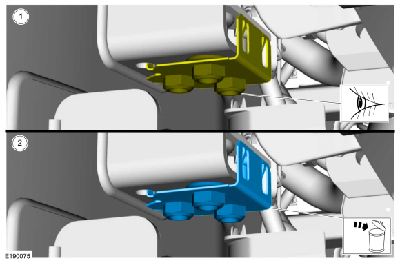
Inspect the engine mount-to-frame nut plate for thread damage.
-
If the nut plate is damaged, remove and discard the engine mount-to-frame nut plate.
-
NOTE:
This step is only necessary when installing a new component.
Clean the engine mount-to-frame mating surfaces of any dirt or foreign material prior to installation.
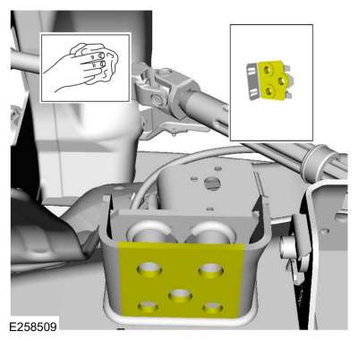
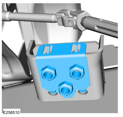
-
NOTE:
This step is only necessary when installing a new component.
Install the nut plate.
-
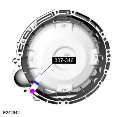
Remove Special Service Tool: 307-346
(T97T-7902-A)
Retainer, Torque Converter.
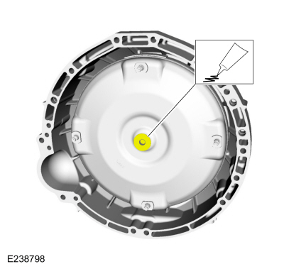
-
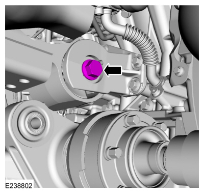
Lubricate the torque converter pilot hub with multi-purpose grease.
Material: Motorcraft® Multi-Purpose Grease Spray
/ XL-5-A
(ESB-M1C93-B)
-
-
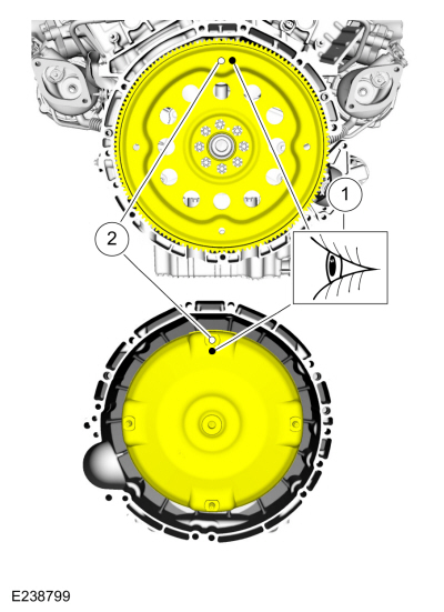
Inspect the torque converter stud and flexplate for paint marks.
-
Align the torque converter stud and flexplate hole near the paint marks to the 12 o'clock position.
-
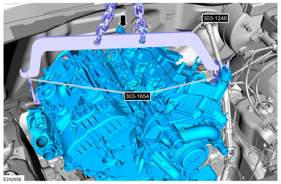
NOTE:
The use of a ratchet strap may be needed to level the engine.
NOTE:
Use a commercially available quick link on the chain to minimize the spread of the chain.
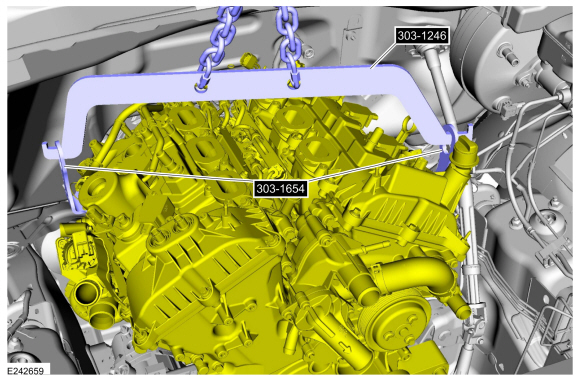
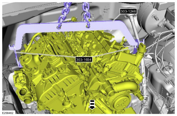
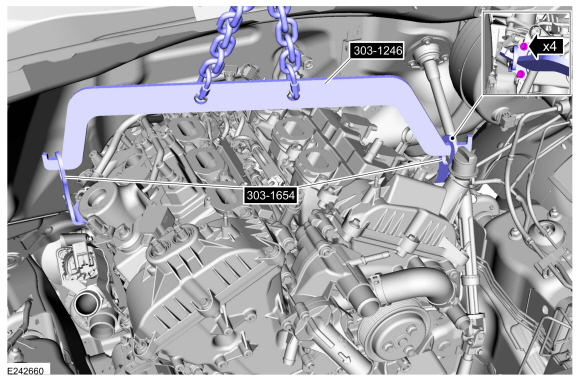
Using the floor crane, lift eyes and the engine spreader bar, position the engine in the engine compartment.
Use Special Service Tool: 303-1246
Engine Spreader Bar.
, 303-1654
Lift Eyes.
Use the General Equipment: Floor Crane
-
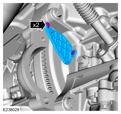
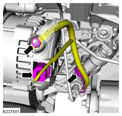
Position back and attach the generator wiring harness retainer to the lower LH side of the engine block.
-
Using the floor crane, lift eyes and the engine spreader bar, position the engine to the transmission.
Use Special Service Tool: 303-1246
Engine Spreader Bar.
, 303-1654
Lift Eyes.
Use the General Equipment: Floor Crane
-
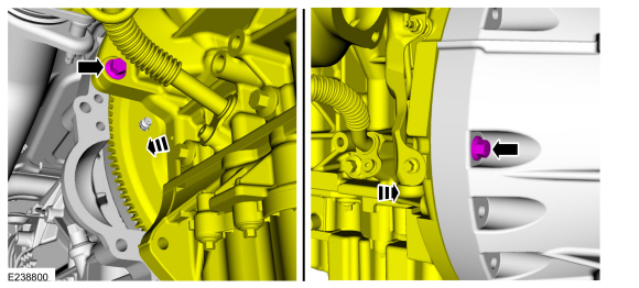
Align the engine to the transmission and draw together using the bolts.
Torque:
35 lb.ft (48 Nm)
-
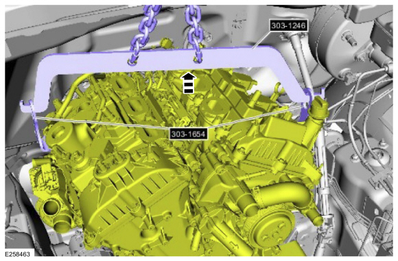
Using the floor crane, lift eyes and the engine spreader bar, raise the engine for clearance to install the LH engine mount.
Use Special Service Tool: 303-1246
Engine Spreader Bar.
, 303-1654
Lift Eyes.
Use the General Equipment: Floor Crane
-
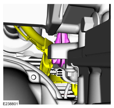
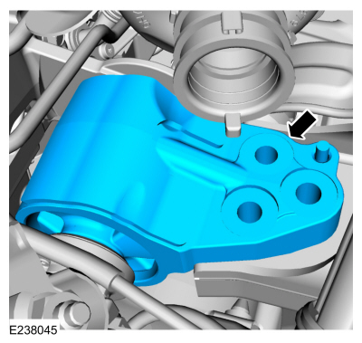
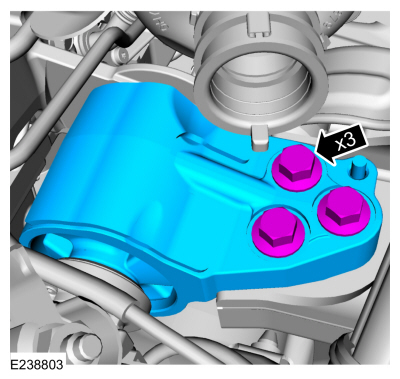
Install the LH engine mount.
-
NOTE:
Use only hand tools when installing the LH engine mount through bolt or the engine mount may be damaged.
-
Install the new LH mount through bolt.
-
Do not torque at this time.
-
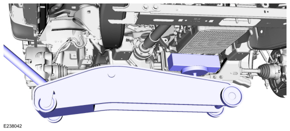
Using the floor crane, lift eyes and the engine spreader bar, lower the engine.
Use Special Service Tool: 303-1246
Engine Spreader Bar.
, 303-1654
Lift Eyes.
Use the General Equipment: Floor Crane
-
Install the new LH engine mount bolts.
Torque:
129 lb.ft (175 Nm)
-
Remove the floor jack and the block of wood.
Use the General Equipment: Trolley Jack
Use the General Equipment: Wooden Block
-
Remove the floor crane, lift eyes and the engine spreader bar.
Use Special Service Tool: 303-1246
Engine Spreader Bar.
, 303-1654
Lift Eyes.
Use the General Equipment: Floor Crane
-
Install the right rear ignition coil.
Refer to: Ignition Coil-On-Plug (303-07 Engine Ignition - 3.5L EcoBoost (272kW/370PS), Removal and Installation).
-
NOTICE:
Only use hand tools when loosening or tightening the
engine mount through bolts or damage to the engine mount-to-cylinder
block bracket can occur.
Tighten the LH engine mount through bolt.
Torque:
258 lb.ft (350 Nm)
-
NOTICE:
Only use hand tools when installing the engine mount nuts and studs or damage to the engine mount can occur.
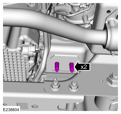
NOTE:
Apply threadlock to the stud threads prior to installation.
Install the RH engine mount studs.
Material: Motorcraft® Threadlock 262
/ TA-26
(WSK-M2G351-A6)
Torque:
22 lb.ft (30 Nm)
-
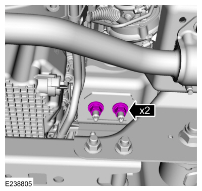
NOTICE:
Only use hand tools when installing the engine mount nuts and studs or damage to the engine mount can occur.
Install the new RH engine mount nuts.
Torque:
111 lb.ft (150 Nm)
-
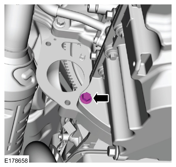
Install the RH side bellhousing bolt.
Torque:
35 lb.ft (48 Nm)
-
Install the LH side bellhousing bolts.
Torque:
35 lb.ft (48 Nm)
-
Install the upper bellhousing bolts.
Torque:
35 lb.ft (48 Nm)
-
Install the lower bellhousing bolt.
Torque:
35 lb.ft (48 Nm)
-
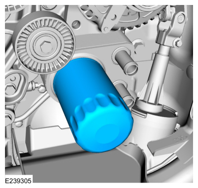
NOTE:
Do not lubricate the engine oil filter gasket.
Install a new oil filter.
Torque:
Stage 1:
44 lb.in (5 Nm)
Stage 2:
180°
-
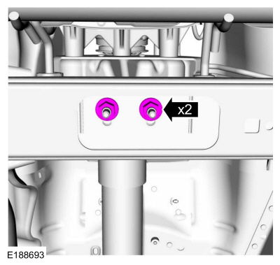
NOTICE:
Only use hand tools when loosening or tightening the
transmission mount-to-crossmember nuts or damage to the transmission
mount can occur.
Remove and discard the transmission mount-to-crossmember nuts. Install new transmission mount-to-crossmember nuts.
Torque:
85 lb.ft (115 Nm)
-
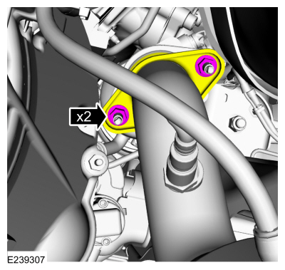
Install the new RH catalytic converter-to-turbocharger nuts.
Torque:
30 lb.ft (40 Nm)
-
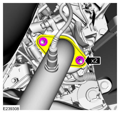
Install the new LH catalytic converter-to-turbocharger nuts.
Torque:
30 lb.ft (40 Nm)
-
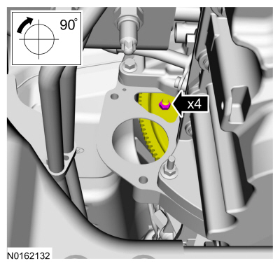
NOTE:
Using the crankshaft pulley bolt, turn the engine clockwise.
Install new torque converter nuts.
Torque:
35 lb.ft (48 Nm)
-
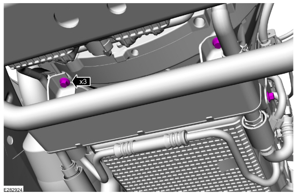
Install the access cover and the retainers.
-
Install the starter motor.
Refer to: Starter Motor (303-06 Starting System - 3.5L EcoBoost (272kW/370PS), Removal and Installation).
-
If equipped.
Install the front driveshaft.
Refer to: Front Driveshaft (205-01 Driveshaft, Removal and Installation).
-
-
Position the transmission fluid cooler back.
-
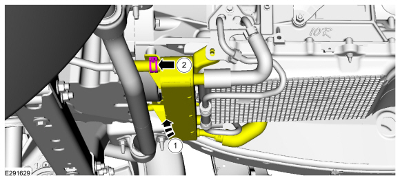
Install the coolant hose and the clamp.
-
Install the transmission cooler bolts.
Torque:
22 lb.ft (30 Nm)
-
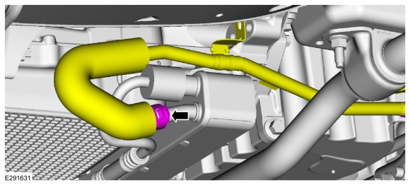
Connect the coolant hose to the transmission fluid cooler.
-
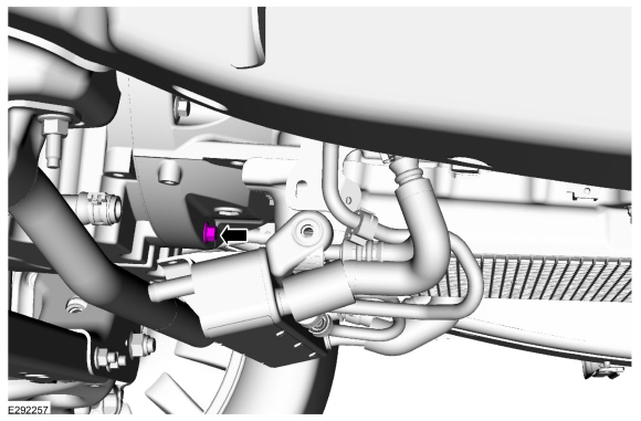
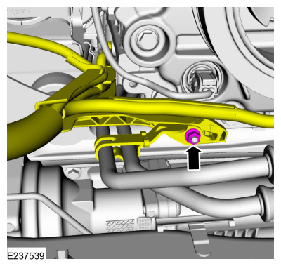
Position back the transmission cooler tube and install the bolt.
-
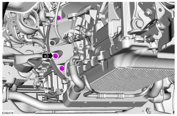
Attach the starter motor wiring harness pin-type retainer and transmission tube pin-type retainer to the oil pan.
Torque:
18 lb.ft (25 Nm)
-
Connect the generator wiring harness to the engine front cover.
-
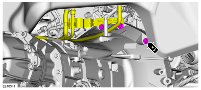
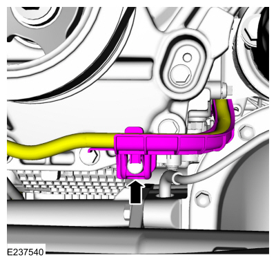
Position back the engine wiring harness. Position back the transmission cooler tubes and install the nut.
Torque:
106 lb.in (12 Nm)
-
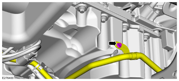
Connect the RH
HO2S electrical connector and the retainer.
-
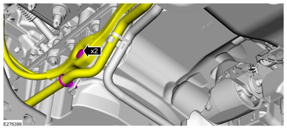
Position back and connect the transmission wire harness retainers.
-
Connect the LH
HO2S electrical connector and the retainer.
-
Install the ground strap and the nut. Connect the ground strap retainers.
Torque:
106 lb.in (12 Nm)
-
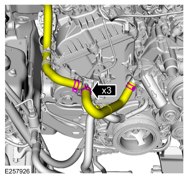
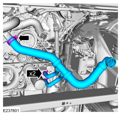
Position back the cabin heater coolant pump hoses and the thermostat housing hose.
Use the General Equipment: Hose Clamp Remover/Installer
-
Connect the lower coolant pump hose.
Use the General Equipment: Hose Clamp Remover/Installer
-
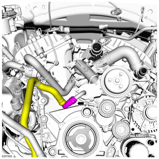
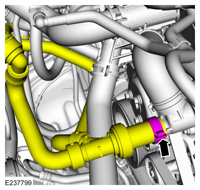
Position back the coolant control valve hose.
Use the General Equipment: Hose Clamp Remover/Installer
-
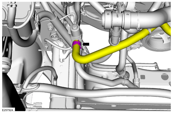
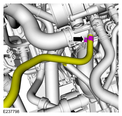
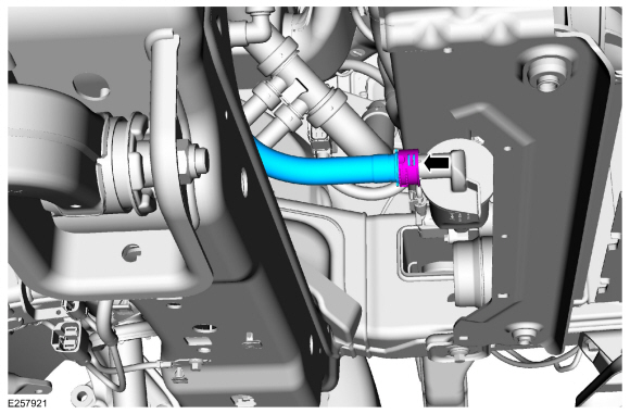
Connect the radiator hose at the thermostat housing.
Use the General Equipment: Hose Clamp Remover/Installer
-
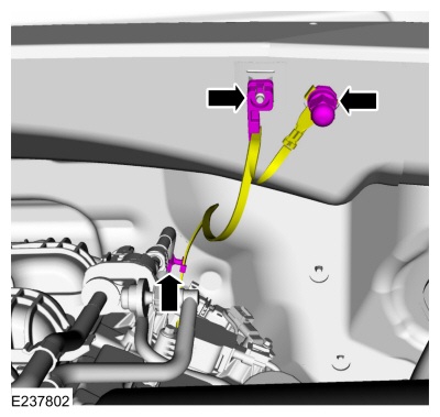
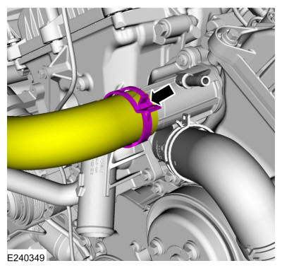
Install the radiator hose. Connect the coolant hoses at the oil cooler.
Use the General Equipment: Hose Clamp Remover/Installer
-
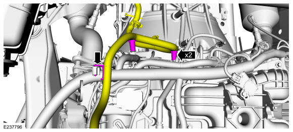
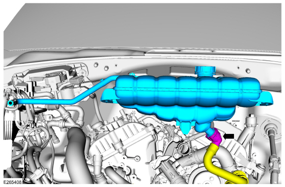
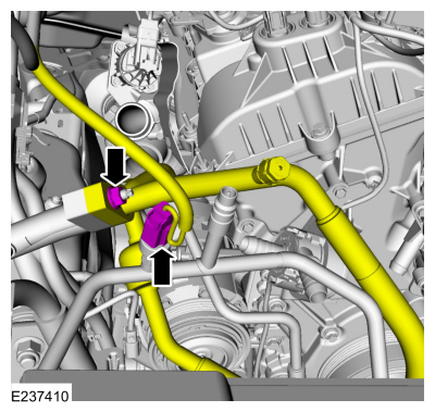
Install the degas bottle hose and connect the coolant hose.
-
Position back the degas bottle hose assembly and connect the coolant hose.
Use the General Equipment: Hose Clamp Remover/Installer
-
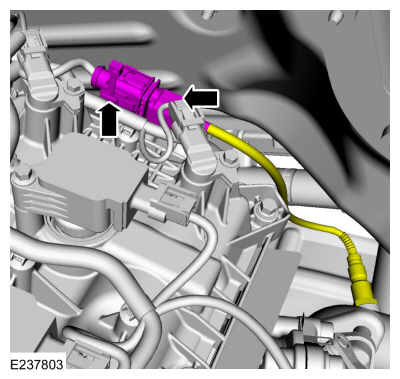
Connect the degas bottle hose at the thermostat housing.
Use the General Equipment: Hose Clamp Remover/Installer
-
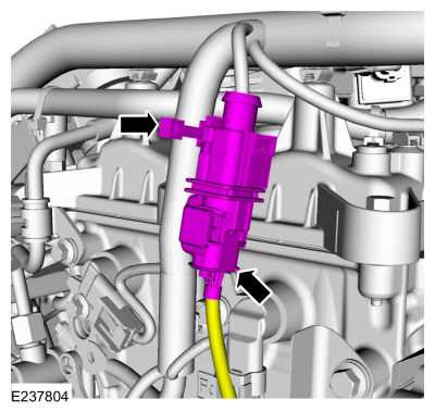
Install the TC bypass valve tube.
Use the General Equipment: Hose Clamp Remover/Installer
-
Position back the CAC tube, install the pin-type retainers and the nuts.
Torque:
53 lb.in (6 Nm)
-
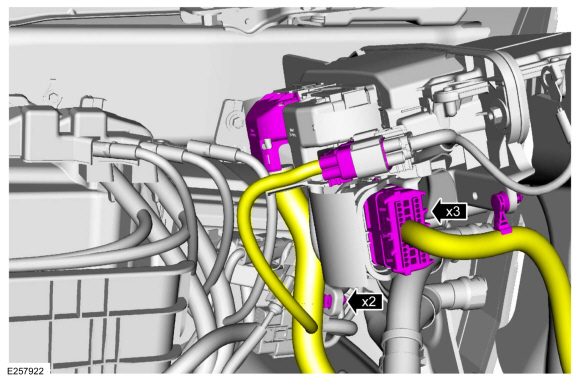
Connect the PCM electrical connectors and the wire harness retainers.
-
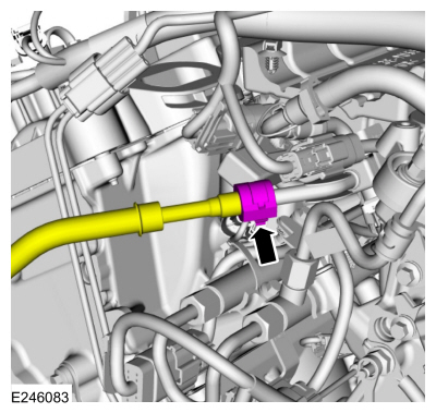
Connect the fuel supply tube quick release coupling.
Refer to: Quick Release Coupling (310-00 Fuel System - General Information - 3.5L EcoBoost (272kW/370PS), General Procedures).
-
Install the intake manifold.
Refer to: Intake Manifold (303-01 Engine - 3.5L EcoBoost (272kW/370PS), Removal and Installation).
-
-
Connect the electrical connector and the wire harness retainer.
-
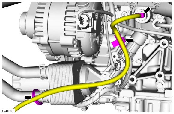
Install the generator nut and position back the boot.
Torque:
150 lb.in (17 Nm)
-
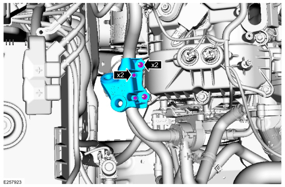
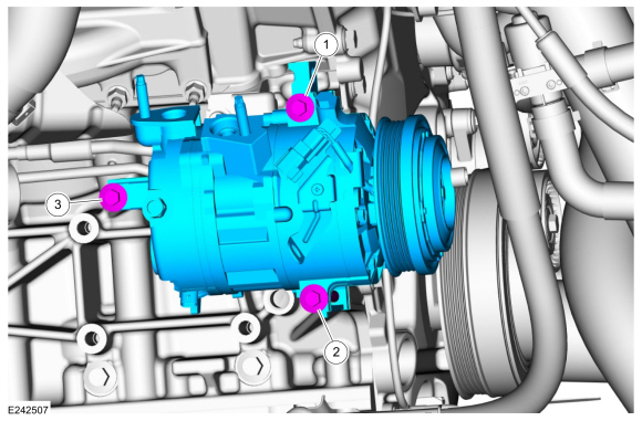
Install the A/C compressor and tighten the bolts in the sequence shown.
Torque:
18 lb.ft (25 Nm)
-
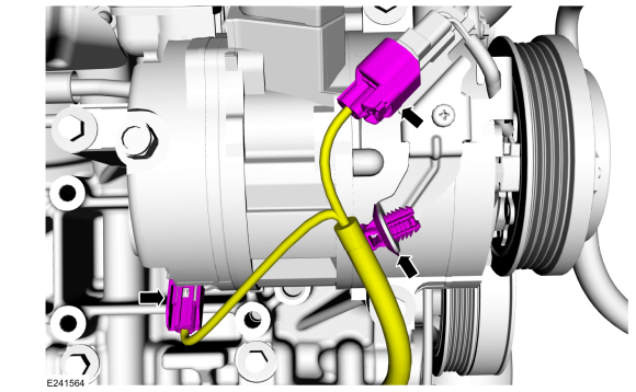
Connect the A/C compressor electrical connectors and the wire harness retainer.
-
-
Install the new O-ring seals.
-
Install the A/C compressor lines.
Torque:
133 lb.in (15 Nm)
-
-
Connect the A/C pressure transducer electrical connector.
-
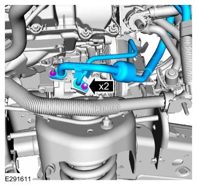
Install a new O-ring seal.
-
Connect the A/C compressor inlet line and install the nut.
Torque:
133 lb.in (15 Nm)
-
Install the A/C compressor belt.
Refer to: Air Conditioning (A/C) Compressor Belt (303-05 Accessory
Drive - 3.5L EcoBoost (272kW/370PS), Removal and Installation).
-
If equipped
-
Connect the wire harness retainer to the coolant hose.
-
Connect the block heater electrical connector and the wire harness retainer.
-
Install the CAC outlet pipe.
Refer to: Charge Air Cooler (CAC) Outlet Pipe (303-12 Intake Air
Distribution and Filtering - 3.5L EcoBoost (272kW/370PS), Removal and
Installation).
-
Install the CAC inlet pipe.
Refer to: Charge Air Cooler (CAC) Intake Pipe (303-12 Intake Air
Distribution and Filtering - 3.5L EcoBoost (272kW/370PS), Removal and
Installation).
-
-
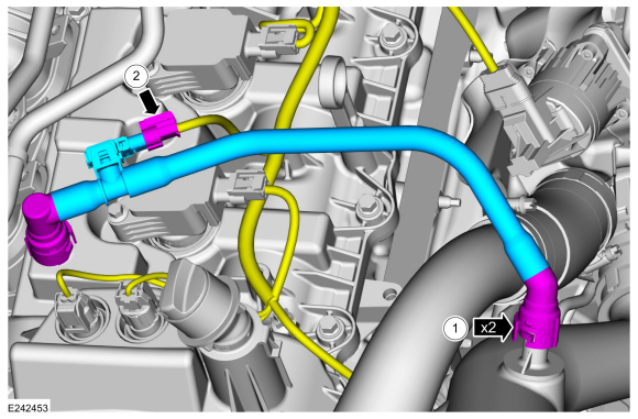
Install the PCV tube and connect the quick release couplings.
Refer to: Quick Release Coupling (310-00 Fuel System - General Information - 3.5L EcoBoost (272kW/370PS), General Procedures).
-
Connect the crankcase pressure sensor electrical connector.
-
Install the cooling module.
Refer to: Cooling Module (303-03 Engine Cooling - 3.5L EcoBoost (272kW/370PS), Removal and Installation).
-
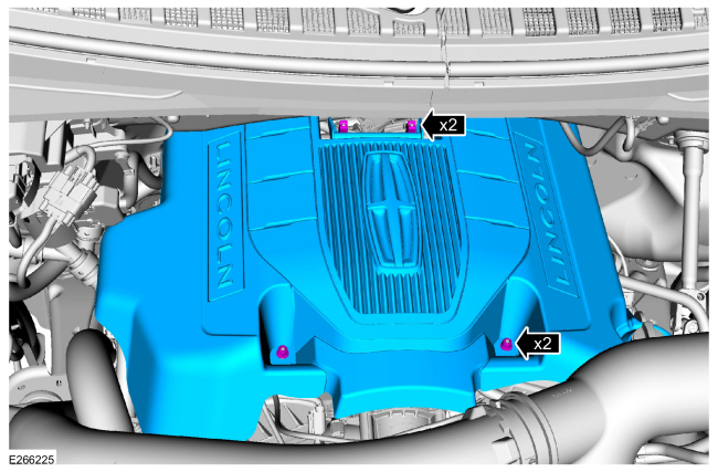
If equipped.
Slide the engine appearance cover into the retaining bracket and install the retainers.
Torque:
97 lb.in (11 Nm)
-
Connect the battery ground cable.
Refer to: Battery Cables (414-01 Battery, Mounting and Cables, Removal and Installation).
-
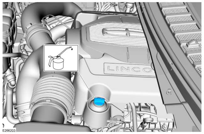
Fill the engine with clean engine oil.
Refer to: Specifications (303-01 Engine - 3.5L EcoBoost (272kW/370PS))
.
-
Pressurize the fuel system.
Refer to: Fuel System Pressure Release (310-00 Fuel System - General
Information - 3.5L EcoBoost (272kW/370PS), General Procedures).
-
If equipped.
-
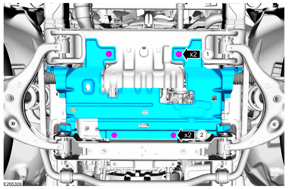
Install the underbody shield and the bolts.
Torque:
30 lb.ft (40 Nm)
-
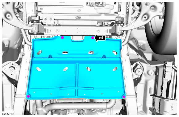
Install the underbody shield and the bolts.
Torque:
71 lb.in (8 Nm)
-
-
If equipped.
Install the transmission housing cover and attach the retainer.
-
Install the bolts.
Torque:
71 lb.in (8 Nm)
-
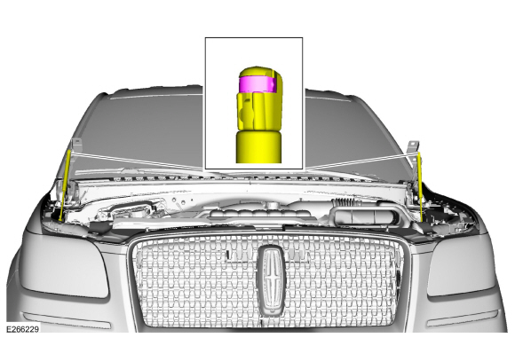
Install the struts.
-
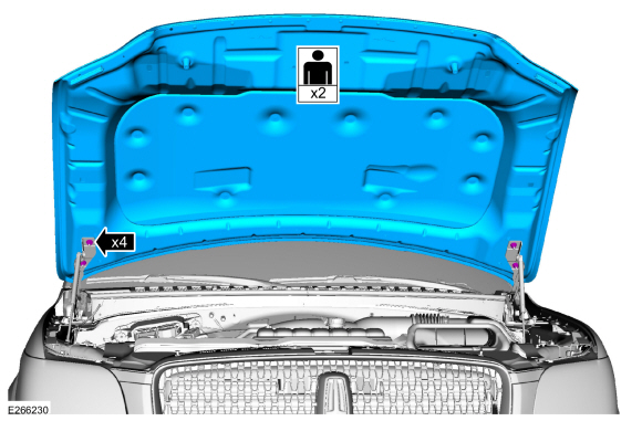
NOTE:
Align the index marks made during hood removal.
Install the hood and the nuts.
Torque:
18 lb.ft (25 Nm)
-
After completing the repairs, perform the Misfire Monitor
Neutral Profile Correction procedure using a diagnostic scan tool.
-
Start and check the exhaust system for leaks.
Other information:
Removal
Remove the engine appearance cover retainers, release
the engine appearance cover from the rear retainers and then remove the
engine appearance cover.
Disconnect the MAPT electrical connector.
Remove the bolt and the MAPT sensor
Installation
..
Removal
WARNING:
The following procedure prescribes critical repair steps
required for correct restraint system operation during a crash. Follow
all notes and steps carefully. Failure to follow step instructions may
result in incorrect operation of the restraint system and increases the
risk of serious personal injury or death in a crash.
NOTE:
Removal steps in this..
 Engine. Assembly
