Lincoln Navigator: Engine - 3.5L EcoBoost (272kW/370PS) / Camshaft LH. Removal and Installation
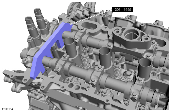
Special Tool(s) / General Equipment
 |
303-1655 Tool, Camshaft Holding |
Removal
NOTICE: During engine repair procedures, cleanliness is extremely important. Any foreign material, including any material created while cleaning gasket surfaces, that enters the oil passages, coolant passages or the oil pan, can cause engine failure.
NOTE: If the RH camshafts are being serviced at the same time as the LH camshafts, remove the RH camshafts first. Refer to the procedure in this section.
NOTE: If the components are to be reinstalled, they must be installed in their original locations.
-
With the vehicle in NEUTRAL, position it on a hoist.
Refer to: Jacking and Lifting (100-02 Jacking and Lifting, Description and Operation).
-
Release the fuel system pressure.
Refer to: Fuel System Pressure Release (310-00 Fuel System - General Information - 3.5L EcoBoost (272kW/370PS), General Procedures).
-
Disconnect the battery ground cable.
Refer to: Battery Disconnect and Connect (414-01 Battery, Mounting and Cables, General Procedures).
Refer to: Battery Cables (414-01 Battery, Mounting and Cables, Removal and Installation).
-
Remove the LH VCT unit.
Refer to: Variable Camshaft Timing (VCT) Unit (303-01 Engine - 3.5L EcoBoost (272kW/370PS), Removal and Installation).
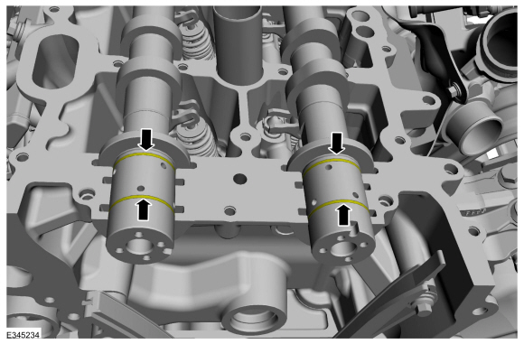
- Remove Special Service Tool: 303-1655 Tool, Camshaft Holding.
 |
-
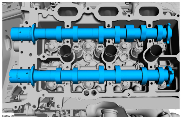
Mark the exhaust and intake camshafts for installation into their original locations.
 |
-
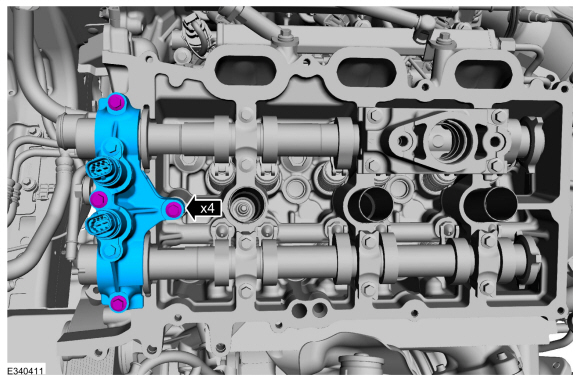
NOTICE: The front camshaft bearing mega cap must be removed first and then the remaining camshaft bearing caps. Failure to follow this direction may result in damage to the engine.
Remove the bolts and the front camshaft bearing mega cap.
 |
-
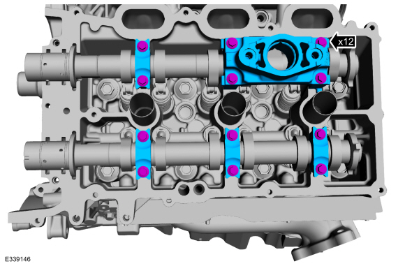
Remove the bolts and the camshaft bearing caps.
 |
-
Remove the intake and exhaust camshaft.
 |
-
-
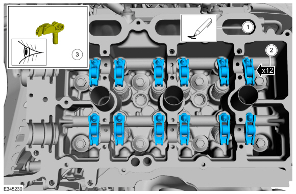
Mark the location of the clipped roller finger
followers and hydraulic lash adjuster assemblies before removal.
-
Remove the clipped roller finger followers and hydraulic lash adjuster assemblies.
-
Inspect the clipped roller finger followers and
hydraulic lash adjuster assemblies for damage. If any damage is found,
inspect the camshaft lobes and valves for damage. Replace damaged
components as necessary.
-
Mark the location of the clipped roller finger
followers and hydraulic lash adjuster assemblies before removal.
 |
Installation
-
NOTE: If the original clipped roller finger follower and hydraulic lash adjuster assembly is to be reinstalled, they must be installed in their original locations.
-
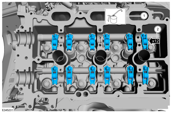
Lubricate the hydraulic lash adjusters with clean engine oil.
Refer to: Specifications (303-01C) .
-
Install the clipped roller finger followers and hydraulic lash adjuster assemblies.
-
Lubricate the hydraulic lash adjusters with clean engine oil.
 |
-
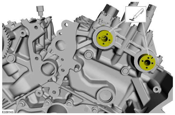
NOTE: Lubricate the camshafts with clean engine oil prior to installation.
Install the intake and exhaust camshaft in the neutral position. Align the D-slots as shown in the illustration.
Refer to: Specifications (303-01C) .
 |
-
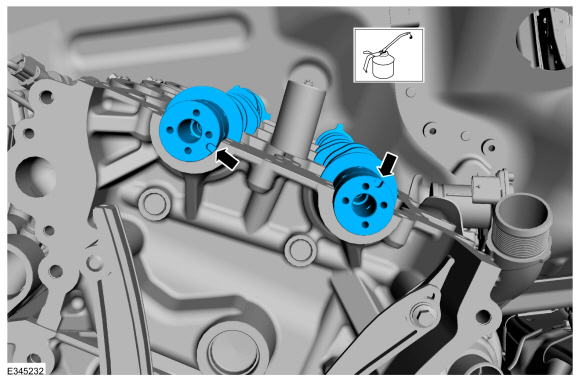
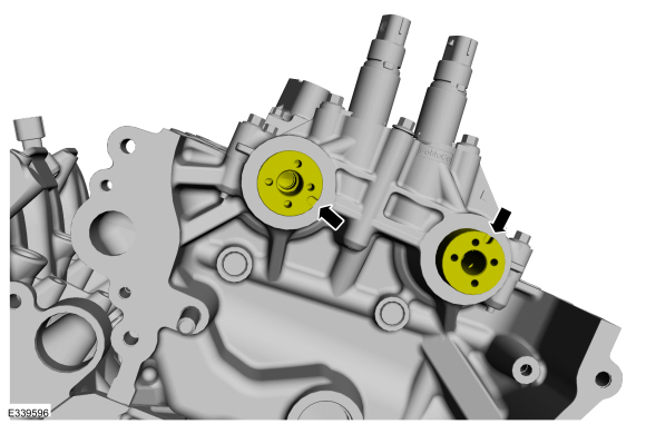
NOTICE: The camshaft seal gaps must be at the 12 o'clock position or damage to the engine may occur.
Position the camshaft seals gaps at 12 o'clock.
 |
-
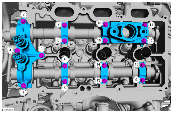
NOTE: Cylinder head camshaft bearing caps are numbered to verify that they are assembled in their original positions.
-
Install camshaft bearing caps by the markings on the caps and hand install the bolts.
-
Install camshaft bearing mega caps and the bolts.
Torque:
Stage 1: 1 thru 3: 71 lb.in (8 Nm)
Stage 2: 1 thru 3: 45°
Stage 3: 4: 97 lb.in (11 Nm)
Stage 4: 4: 45°
Stage 5: 5 thru 16: 71 lb.in (8 Nm)
Stage 6: 5 thru 16: 11°
Stage 7: Loosen 12 and 11: Loosen: turn(s)
Stage 8: 12 and 11: 71 lb.in (8 Nm)
Stage 9: 12 and 11: 11°
Stage 10: Loosen 10 and 9: Loosen: turn(s)
Stage 11: 10 and 9: 71 lb.in (8 Nm)
Stage 12: 10 and 9: 11°
Stage 13: Loosen 8 and 7: Loosen: turn(s)
Stage 14: 8 and 7: 71 lb.in (8 Nm)
Stage 15: 8 and 7: 11°
Stage 16: Loosen 6 and 5: Loosen: turn(s)
Stage 17: 6 and 5: 71 lb.in (8 Nm)
Stage 18: 6 and 5: 11°
-
Install camshaft bearing caps by the markings on the caps and hand install the bolts.
 |
-
Rotate the LH camshafts to TDC .
 |
-
NOTE: The Camshaft Holding Tool will hold the camshafts in the TDC position.
Install Special Service Tool: 303-1655 Tool, Camshaft Holding.
|
-
Install the LH VCT unit.
Refer to: Variable Camshaft Timing (VCT) Unit (303-01 Engine - 3.5L EcoBoost (272kW/370PS), Removal and Installation).
-
Connect the battery ground cable.
Refer to: Battery Disconnect and Connect (414-01 Battery, Mounting and Cables, General Procedures).
Refer to: Battery Cables (414-01 Battery, Mounting and Cables, Removal and Installation).
-
After completing the repairs, perform the Misfire
Monitor Neutral Profile Correction procedure using a diagnostic scan
tool.
-
Road test the vehicle.
 Engine. Diagnosis and Testing
For gas engine mechanical diagnosis and testing, REFER to: Engine (303-00 Engine System - General Information, Diagnosis and Testing). For DTC (Diagnostic Trouble Code) related concerns, REFER to the Master DTC Chart...
 Camshaft RH. Removal and Installation
Special Tool(s) /
General Equipment
303-1655Tool, Camshaft Holding
Removal
NOTICE:
During engine repair procedures, cleanliness is extremely
important...
Other information:
Lincoln Navigator 2018-2026 Workshop Manual: Front Bumper Bracket. Removal and Installation
Special Tool(s) / General Equipment Grinder MIG/MAG Welding Equipment Locking Pliers Removal WARNING: Frame rail crush zones absorb crash energy during a collision and must be replaced if damaged. Prior to replacement of frame rail crush zones, straighten damaged frame rails to correct frame dimensions...
Lincoln Navigator 2018-2026 Workshop Manual: B Clutch. Description and Operation
Overview Item Description 1 SSB 2 B clutch control valve 3 B clutch latch valve 4 B clutch apply circuit 5 B clutch piston 6 B clutch assembly 7 One-Way Clutch (OWC) ..
Categories
- Manuals Home
- 4th Gen Lincoln Navigator Service Manual (2018 - 2026)
- All Terrain Control Module (ATCM). Removal and Installation
- Brake Service Mode Activation and Deactivation. General Procedures
- Front Seat. Removal and Installation
- Windshield Washer Pump. Removal and Installation
- Telematics Control Unit (TCU) Module. Removal and Installation
Rear Camber Adjustment. General Procedures
Special Tool(s) / General Equipment
Wheel Alignment SystemActivation
NOTICE: Suspension fasteners are critical parts that affect the performance of vital components and systems. Failure of these fasteners may result in major service expense. Use the same or equivalent parts if replacement is necessary. Do not use a replacement part of lesser quality or substitute design. Tighten fasteners as specified.
Using alignment equipment and the manufacturer's instructions, measure the rear camber.Use the General Equipment: Wheel Alignment System