Lincoln Navigator: Engine - 3.5L EcoBoost (272kW/370PS) / Camshaft RH. Removal and Installation
Special Tool(s) / General Equipment
 |
303-1655 Tool, Camshaft Holding |
Removal
NOTICE: During engine repair procedures, cleanliness is extremely important. Any foreign material, including any material created while cleaning gasket surfaces, that enters the oil passages, coolant passages or the oil pan, can cause engine failure.
NOTE: If the components are to be reinstalled, they must be installed in their original locations.
-
With the vehicle in NEUTRAL, position it on a hoist.
Refer to: Jacking and Lifting (100-02 Jacking and Lifting, Description and Operation).
-
Release the fuel system pressure.
Refer to: Fuel System Pressure Release (310-00 Fuel System - General Information - 3.5L EcoBoost (272kW/370PS), General Procedures).
-
Disconnect the battery ground cable.
Refer to: Battery Disconnect and Connect (414-01 Battery, Mounting and Cables, General Procedures).
Refer to: Battery Cables (414-01 Battery, Mounting and Cables, Removal and Installation).
-
Remove the RH VCT unit.
Refer to: Variable Camshaft Timing (VCT) Unit (303-01 Engine - 3.5L EcoBoost (272kW/370PS), Removal and Installation).
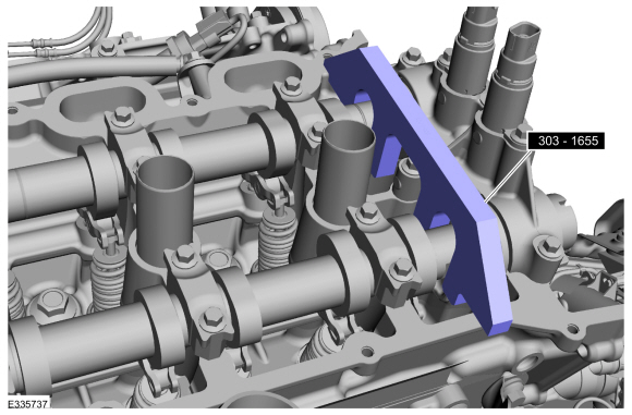
- Remove Special Service Tool: 303-1655 Tool, Camshaft Holding.
 |
-
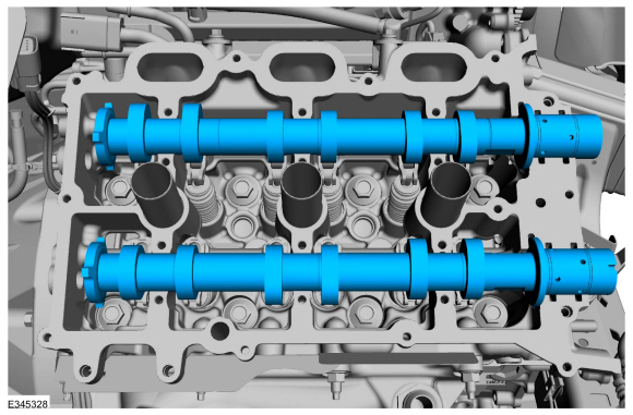
Mark the exhaust and intake camshafts for installation into their original locations.
 |
-
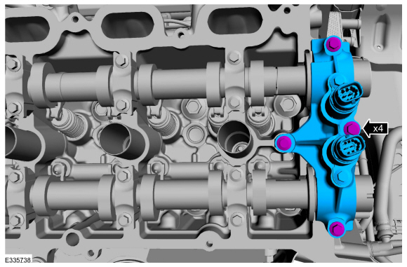
NOTICE: The front camshaft bearing mega cap must be removed first and then the remaining camshaft bearing caps. Failure to follow this direction may result in damage to the engine.
Remove the bolts and the front camshaft bearing mega cap.
 |
-
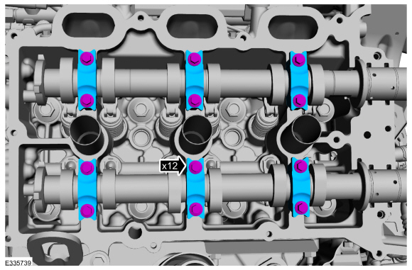
Remove the bolts and the camshaft bearing caps.
 |
-
Remove the intake and exhaust camshaft.
 |
-
-
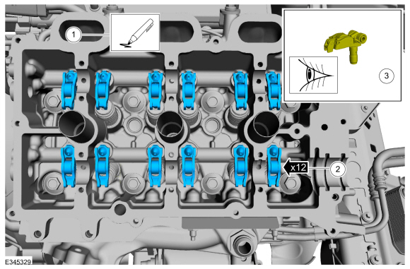
Mark the location of the clipped roller finger
followers and hydraulic lash adjuster assemblies before removal.
-
Remove the clipped roller finger followers and hydraulic lash adjuster assemblies.
-
Inspect the clipped roller finger followers and
hydraulic lash adjuster assemblies for damage. If any damage is found,
inspect the camshaft lobes and valves for damage. Replace damaged
components as necessary.
-
Mark the location of the clipped roller finger
followers and hydraulic lash adjuster assemblies before removal.
 |
Installation
-
NOTE: If the original clipped roller finger follower and hydraulic lash adjuster assembly is to be reinstalled, they must be installed in their original locations.
-
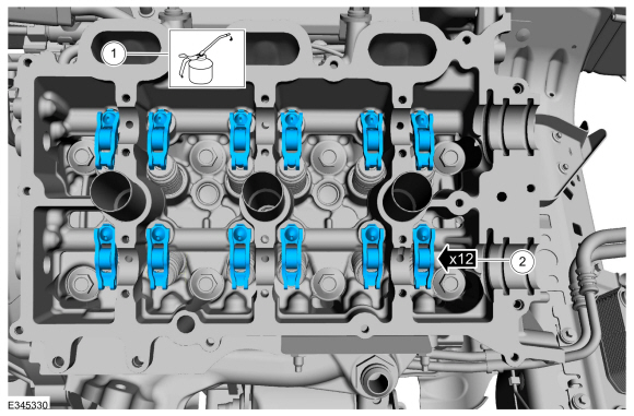
Lubricate the hydraulic lash adjusters with clean engine oil.
Refer to: Specifications (303-01C) .
-
Install the clipped roller finger followers and hydraulic lash adjuster assemblies.
-
Lubricate the hydraulic lash adjusters with clean engine oil.
 |
-
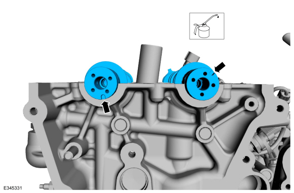
NOTE: Lubricate the camshafts with clean engine oil prior to installation.
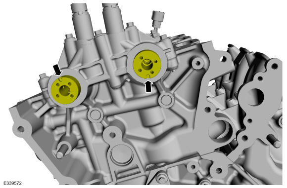
Install the intake and exhaust camshaft in the neutral position. Align the D-slots as shown in the illustration.
Refer to: Specifications (303-01C) .
 |
-
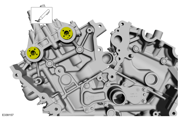
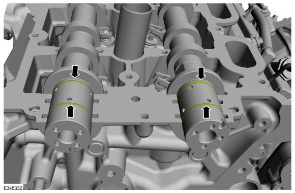
NOTICE: The camshaft seal gaps must be at the 12 o'clock position or damage to the engine may occur.
Position the camshaft seals gaps at 12 o'clock.
 |
-
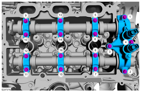
NOTE: Cylinder head camshaft bearing caps are numbered to verify that they are assembled in their original positions.
-
Install camshaft bearing caps by the markings on the caps and hand install the bolts.
-
Install camshaft bearing mega caps and the bolts.
Torque:
Stage 1: 1 thru 3: 71 lb.in (8 Nm)
Stage 2: 1 thru 3: 45°
Stage 3: 4: 97 lb.in (11 Nm)
Stage 4: 4: 45°
Stage 5: 5 thru 16: 71 lb.in (8 Nm)
Stage 6: 5 thru 16: 11°
Stage 7: Loosen 12 and 11: Loosen: turn(s)
Stage 8: 12 and 11: 71 lb.in (8 Nm)
Stage 9: 12 and 11: 11°
Stage 10: Loosen 10 and 9: Loosen: turn(s)
Stage 11: 10 and 9: 71 lb.in (8 Nm)
Stage 12: 10 and 9: 11°
Stage 13: Loosen 8 and 7: Loosen: turn(s)
Stage 14: 8 and 7: 71 lb.in (8 Nm)
Stage 15: 8 and 7: 11°
Stage 16: Loosen 6 and 5: Loosen: turn(s)
Stage 17: 6 and 5: 71 lb.in (8 Nm)
Stage 18: 6 and 5: 11°
-
Install camshaft bearing caps by the markings on the caps and hand install the bolts.
 |
-
Rotate the RH camshafts to TDC .
 |
-
NOTE: The Camshaft Holding Tool will hold the camshafts in the TDC position.
Install Special Service Tool: 303-1655 Tool, Camshaft Holding.
|
-
NOTE: Do not install the valve cover at this time.
Install the RH VCT unit.
Refer to: Variable Camshaft Timing (VCT) Unit (303-01 Engine - 3.5L EcoBoost (272kW/370PS), Removal and Installation).
-
Connect the battery ground cable.
Refer to: Battery Disconnect and Connect (414-01 Battery, Mounting and Cables, General Procedures).
Refer to: Battery Cables (414-01 Battery, Mounting and Cables, Removal and Installation).
-
After completing the repairs, perform the Misfire
Monitor Neutral Profile Correction procedure using a diagnostic scan
tool.
-
Road test the vehicle.
 Camshaft LH. Removal and Installation
Special Tool(s) /
General Equipment
303-1655Tool, Camshaft Holding
Removal
NOTICE:
During engine repair procedures, cleanliness is extremely
important...
 Crankshaft Front Seal. Removal and Installation
Special Tool(s) /
General Equipment
303-102Installer, Crankshaft Pulley
303-1251Installer, Front SealTKIT-2006UF-FLMTKIT-2006UF-ROW
303-409
(T92C-6700-CH)
Remover, Crankshaft SealTKIT-1992-FH/FMH/FLMHTKIT-1993-LMH/MH
Strap Wrench
Three Leg Puller
Removal
NOTICE:
During engine repair procedures, cleanliness is extremely
import..
Other information:
Lincoln Navigator 2018-2026 Workshop Manual: Brake Fluid Reservoir. Removal and Installation
Removal NOTE: Removal steps in this procedure may contain installation details. Remove the EBB . Refer to: Electric Brake Booster (EBB) (206-09 Anti-Lock Brake System (ABS) and Stability Control, Removal and Installation). Remove the brake fluid reservoir cap. Remove the brake fluid reservoir filter a..
Lincoln Navigator 2018-2026 Workshop Manual: Instrument Panel Cluster (IPC) - Overview. Description and Operation
Overview The IPC uses gauges, warning and informational indicators, RTT indicators, warning messages and chimes to alert the driver of vehicle conditions and system operation. The message center provides menu selections to configure various vehicle features. For a complete list and description of the features the message center controls, refer to the Owner's Literature. Informational..
Categories
- Manuals Home
- 4th Gen Lincoln Navigator Service Manual (2018 - 2026)
- Telematics Control Unit (TCU) Module. Removal and Installation
- Liftgate Trim Panel. Removal and Installation
- Brake Service Mode Activation and Deactivation. General Procedures
- Power Running Board (PRB). Diagnosis and Testing
- Remote Function Actuator (RFA) Module. Removal and Installation
Rear Stabilizer Bar Link. Removal and Installation
Removal
NOTE: Removal steps in this procedure may contain installation details.
With the vehicle in NEUTRAL, position it on a hoist.Refer to: Jacking and Lifting (100-02 Jacking and Lifting, Description and Operation).
NOTE: Use the hex-holding feature to prevent the stud from turning while removing the nut.
Remove and discard the 2 rear stabilizer bar link nuts and remove the rear stabilizer bar link.Torque: 46 lb.ft (63 Nm)
