Lincoln Navigator: Supplemental Restraint System / Restraints Control Module (RCM). Removal and Installation
Removal
 WARNING:
The following procedure prescribes critical repair steps
required for correct restraint system operation during a crash. Follow
all notes and steps carefully. Failure to follow step instructions may
result in incorrect operation of the restraint system and increases the
risk of serious personal injury or death in a crash.
WARNING:
The following procedure prescribes critical repair steps
required for correct restraint system operation during a crash. Follow
all notes and steps carefully. Failure to follow step instructions may
result in incorrect operation of the restraint system and increases the
risk of serious personal injury or death in a crash.
NOTE: Removal steps in this procedure may contain installation details.
-
Refer to: Pyrotechnic Device Health and Safety Precautions (100-00 General Information, Description and Operation).
WARNING:
Before beginning any service procedure in this
manual, refer to health and safety warnings in section 100-00 General
Information. Failure to follow this instruction may result in serious
personal injury.
-
NOTE: This step is only necessary when installing a new component.
NOTE: The PMI (programmable module installation) process must begin with the current RCM (restraints control module) installed. If the current RCM (restraints control module) does not respond to the diagnostic scan tool, the tool may prompt for As-Built Data as part of the repair.
Using a diagnostic scan tool, begin the PMI process for the RCM following the on-screen instructions.
-
Depower the SRS .
Refer to: Supplemental Restraint System (SRS) Depowering (501-20 Supplemental Restraint System) .
-
Remove the floor console.
Refer to: Floor Console (501-12 Instrument Panel and Console, Removal and Installation).
-
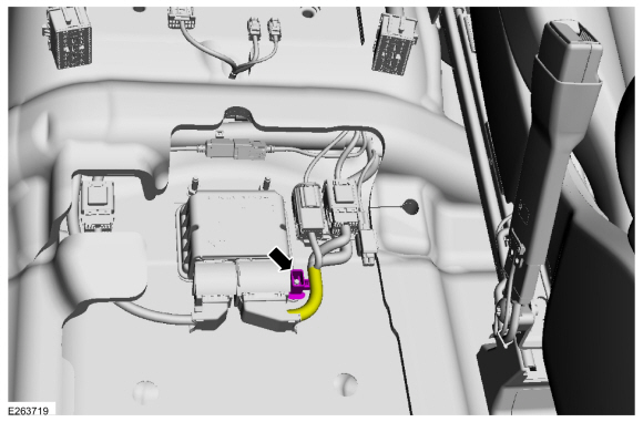
Detach the wiring harness retainers.
 |
-
-
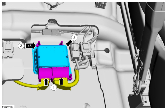
Disconnect the RCM electrical connectors.
-
Remove the bolts.
Torque: 106 lb.in (12 Nm)
-
Remove the RCM .
-
Disconnect the RCM electrical connectors.
 |
Installation
WARNING:
Incorrect repair techniques or actions can cause an
accidental Supplemental Restraint System deployment. Make sure the
restraint system is depowered before reconnecting the component. Refer
to the Supplemental Restraint System depowering General Procedure in
section 501-20B. Failure to precisely follow depowering instructions
could result in serious personal injury from an accidental deployment.
-
To install, reverse the removal procedure.
-
Repower the SRS . For a new RCM , do not prove out the SRS at this time.
Refer to: Supplemental Restraint System (SRS) Repowering (501-20 Supplemental Restraint System) .
-
NOTE: This step is only necessary when installing a new RCM (restraints control module).
Using a diagnostic scan tool, complete the PMI process for the RCM following the on-screen instructions.
-
NOTE: This step is only necessary when installing a new RCM (restraints control module).
Carry out the ABS Calibration service functions using the diagnostic scan tool and following the on-screen instructions.
-
If a new RCM was installed, prove out the SRS
. Verify all airbags are installed and connected and the ignition is
OFF. Wait 10 seconds, then turn the ignition ON and monitor the airbag
warning indicator. The airbag warning indicator illuminates continuously
for approximately 6 seconds and then turns off. Continue to monitor the
airbag warning indicator for approximately 30 seconds, as this is the
time required for the RCM to complete testing of the SRS .
-
If a SRS
fault is present, the airbag warning indicator either fails to light,
remains lit continuously or flashes. The flashing may not occur until
approximately 30 seconds after the ignition has been turned from OFF to
ON. If this occurs, diagnose and repair any SRS faults before proceeding with other repairs.
-
If, after the ignition has been turned on for 30
seconds, the airbag warning indicator remains unlit with no chime or SRS
message displayed in the message center, no SRS fault is present.
-
If the airbag warning indicator is inoperative and a SRS
fault exists, a chime sounds in a pattern of 5 sets of 5 beeps or a
message displays in the message center. If this occurs, diagnose and
repair the airbag warning indicator and any SRS faults before proceeding with other repairs.
-
If a SRS
fault is present, the airbag warning indicator either fails to light,
remains lit continuously or flashes. The flashing may not occur until
approximately 30 seconds after the ignition has been turned from OFF to
ON. If this occurs, diagnose and repair any SRS faults before proceeding with other repairs.
 Passenger Airbag. Removal and Installation
Removal
WARNING:
The following procedure prescribes critical repair steps
required for correct supplemental restraint system operation during a
crash...
 Seat Position Sensor. Removal and Installation
Removal
NOTE:
LH seat shown, RH seat similar.
NOTE:
Removal steps in this procedure may contain installation details.
Raise the seat to the full up position...
Other information:
Lincoln Navigator 2018-2026 Workshop Manual: Rear Parking Aid Camera. Removal and Installation
Removal NOTE: Removal steps in this procedure may contain installation details. Remove the reversing lamp. Refer to: Reversing Lamp (417-01 Exterior Lighting, Removal and Installation). Disconnect the electrical connector , the washer hose and position the wiring harness...
Lincoln Navigator 2018-2026 Workshop Manual: Wheel to Tire Runout Minimization. General Procedures
Check NOTICE: Non-Hunter brand balancers will not include the Ford-approved procedure for match-mounting in their software. NOTICE: Other balancing procedures that exist on non-Hunter brand equipment are not Ford approved and should not be used...
Categories
- Manuals Home
- 4th Gen Lincoln Navigator Service Manual (2018 - 2026)
- Head Up Display (HUD) Module Calibration. General Procedures
- Windshield Washer Pump. Removal and Installation
- Front Bumper Cover. Removal and Installation
- Transmission Fluid Drain and Refill. General Procedures
- Telematics Control Unit (TCU) Module. Removal and Installation
Front Driveshaft. Removal and Installation
Special Tool(s) / General Equipment
Crimping ToolMaterials
Name Specification Motorcraft® Premium Long-Life GreaseXG-1-E1 ESA-M1C75-B
Removal
With the vehicle in NEUTRAL, position the vehicle on a hoist.Refer to: Jacking and Lifting (100-02 Jacking and Lifting, Description and Operation).
Remove the bolts and the transmission shield.