
Lincoln Navigator: Supplemental Restraint System / Seat Position Sensor. Removal and Installation
Removal
NOTE: LH seat shown, RH seat similar.
NOTE: Removal steps in this procedure may contain installation details.
-
Raise the seat to the full up position.
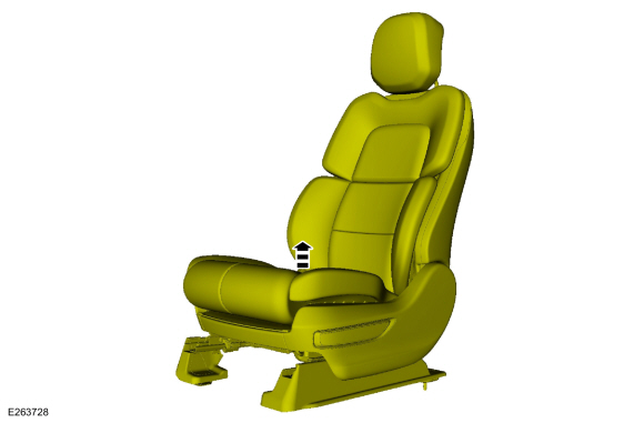 |
-
-
Disconnect the electrical connector.
-
Remove the screw.
Torque: 8 lb.in (0.9 Nm)
-
Remove the seat position sensor.
-
Disconnect the electrical connector.
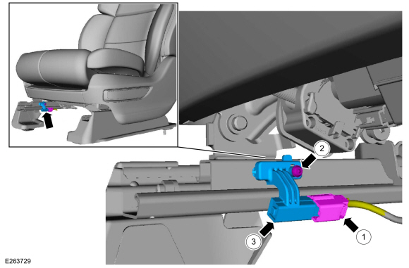 |
Installation
-
To install, reverse the removal procedure.
 Restraints Control Module (RCM). Removal and Installation
Removal
WARNING:
The following procedure prescribes critical repair steps
required for correct restraint system operation during a crash...
 Side Curtain Airbag. Removal and Installation
Removal
WARNING:
The following procedure prescribes critical repair steps
required for correct restraint system operation during a crash...
Other information:
Lincoln Navigator 2018-2026 Workshop Manual: Air Conditioning (A/C) System Flushing. General Procedures
Materials Name Specification Motorcraft® A/C System Flushing SolventYN-23 - Flushing NOTICE: Use the Refrigerant Identification Equipment before recovering any of the vehicle's refrigerant. Failure to do so puts the shop's bulk refrigerant at risk of contamination...
Lincoln Navigator 2018-2026 Workshop Manual: Front Door Check Arm. Removal and Installation
Removal NOTE: Removal steps in this procedure may contain installation details. NOTE: LH side shown, RH side similar. Open the door. Remove the check arm bolt. Torque: 17 lb...
Categories
- Manuals Home
- 4th Gen Lincoln Navigator Service Manual (2018 - 2026)
- Brake Service Mode Activation and Deactivation. General Procedures
- Head Up Display (HUD) Module Calibration. General Procedures
- Vehicle Dynamics Control Module (VDM). Removal and Installation
- Neutral Flat Tow Activation and Deactivation. General Procedures
- Transmission Fluid Drain and Refill. General Procedures
Rear Drive Halfshafts. Diagnosis and Testing
Preliminary Inspection
Visually inspect the CV joints, housing, boots, and clamps for obvious signs of mechanical damage.If an obvious cause for an observed or reported concern is found, correct the cause (if possible) before proceeding to the next step
If the cause is not visually evident, verify the symptom and REFER to Symptom Chart: NVH.
