Lincoln Navigator: Rear End Sheet Metal Repairs / Rear Crossmember. Removal and Installation
Special Tool(s) / General Equipment
| 6.5 mm Drill Bit | |
| Polydrive Bit Socket | |
| Rivet Gun | |
| Self-Piercing Rivet (SPR) Remover/Installer | |
| Belt Sander | |
| Locking Pliers |
Materials
| Name | Specification |
|---|---|
| Metal Bonding Adhesive TA-1, TA-1-B, 3M™ 08115, LORD Fusor® 108B, Henkel Teroson EP 5055 |
- |
| Seam Sealer TA-2-B, 3M™ 08308, LORD Fusor® 803DTM |
- |
Removal
NOTICE: Panel sectioning is prohibited within 50 mm of door hinge, door striker, restraints and suspension anchoring points.
NOTE: Self-piercing rivet (SPR) fasteners may not be placed directly over original self-piercing rivet (SPR) location. They must be placed adjacent to original location matching original quantity.
NOTE: Aluminum body panels are highly receptive to heat transfer. With the extensive use of structural adhesives and non-structural sealers used in vehicle construction, the potential of heat transfer could impact adhesives and sealers in non-associated panels during the repair process. Many repairs areas that utilize structural adhesive may be separated after fastener removal by using a panel chisel along the joint/flange. Using heat not exceeding 425° F to loosen a bonded panel should only be done when all panels in the joint will be replaced and new adhesive applied.
NOTE: Flow-drill screw (FDS) fasteners are not reused. Remove and discard.
NOTE: Right-hand (RH) side shown, left-hand (LH) side similar.
NOTE: Standard wheelbase shown, long wheelbase similar.
-
Depower the SRS .
Refer to: Supplemental Restraint System (SRS) Depowering (501-20B Supplemental Restraint System, General Procedures).
-
If Necessary:
Dimensionally restore the vehicle to pre-damage condition.
Refer to: Body and Frame (501-26 Body Repairs - Vehicle Specific Information and Tolerance Checks, Description and Operation).
-
On Both Sides: Remove the closeout panel only.
Refer to: Rear Lamp Mounting Panel (501-30 Rear End Sheet Metal Repairs, Removal and Installation).
-
On Both Sides:
Remove the floor panel reinforcement.
Refer to: Rear Floor Panel Reinforcement (501-30 Rear End Sheet Metal Repairs, Removal and Installation).
-
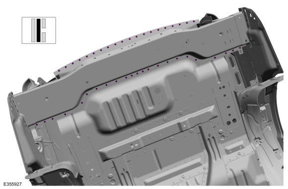
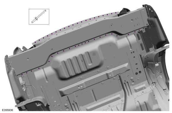
Remove the fasteners.
Use the General Equipment: Self-Piercing Rivet (SPR) Remover/Installer
Use the General Equipment: Belt Sander
Use the General Equipment: Polydrive Bit Socket
 |
-
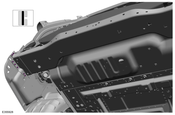
Remove the fasteners.
Use the General Equipment: Self-Piercing Rivet (SPR) Remover/Installer
Use the General Equipment: Belt Sander
Use the General Equipment: Polydrive Bit Socket
 |
-
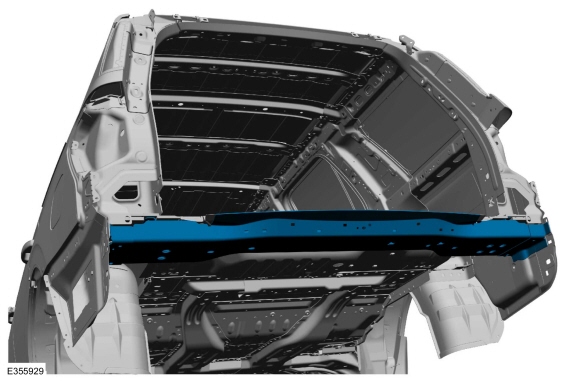
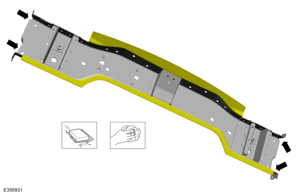
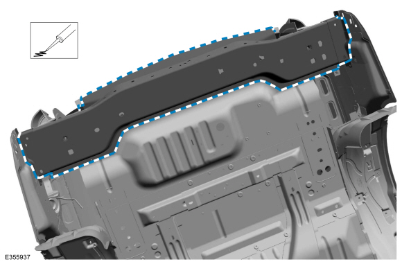
Break the adhesive bond and remove the rear crossmember.
 |
Installation
NOTICE: Panel sectioning is prohibited within 50 mm of door hinge, door striker, restraints and suspension anchoring points.
NOTE: Self-piercing rivet (SPR) fasteners may not be placed directly over original self-piercing rivet (SPR) location. They must be placed adjacent to original location matching original quantity.
NOTE: Aluminum body panels are highly receptive to heat transfer. With the extensive use of structural adhesives and non-structural sealers used in vehicle construction, the potential of heat transfer could impact adhesives and sealers in non-associated panels during the repair process. Many repairs areas that utilize structural adhesive may be separated after fastener removal by using a panel chisel along the joint/flange. Using heat not exceeding 425° F to loosen a bonded panel should only be done when all panels in the joint will be replaced and new adhesive applied.
NOTE: Right-hand (RH) side shown, left-hand (LH) side similar.
NOTE: Standard wheelbase shown, long wheelbase similar.
-
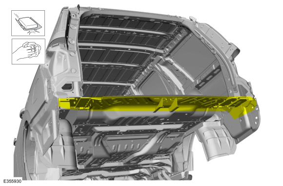
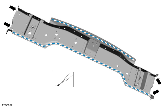
80-120 Grit Sand Paper:
Sand to remove old adhesive, paint, e-coat and clean.
 |
-
80-120 Grit Sand Paper:
Sand to remove e-coat and clean.
 |
-
Apply adhesive.
Material: Metal Bonding Adhesive / TA-1, TA-1-B, 3M™ 08115, LORD Fusor® 108B, Henkel Teroson EP 5055
 |
-
Install, properly position and clamp the rear crossmember, drill for fasteners.
Use the General Equipment: Locking Pliers
Use the General Equipment: 6.5 mm Drill Bit
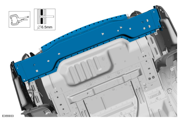 |
-
On Both Sides:
Drill for fasteners.
Use the General Equipment: 6.5 mm Drill Bit
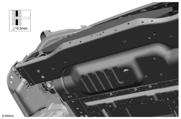 |
-
On Both Sides:
Install the fasteners.
Use the General Equipment: Rivet GunItem SPR Number SPR Code Henrob®, Car-O-Liner ®, CMO®, Chief®, Spanesi®, Wielander and Schill® Mandrel Pro- Spot ® Mandrel Blind Rivet Solid rivet Rivnut® 1 - - - - W702512-S900C - -
 |
-
Install the fasteners.
Use the General Equipment: Rivet GunItem SPR Number SPR Code Henrob®, Car-O-Liner ®, CMO®, Chief®, Spanesi®, Wielander and Schill® Mandrel Pro- Spot ® Mandrel Blind Rivet Solid rivet Rivnut® 1 - - - - W702512-S900C - -
 |
-
Seam Sealing:
All seams must be sealed to production level.
Material: Seam Sealer / TA-2-B, 3M™ 08308, LORD Fusor® 803DTM
 |
-
Refinish the repair using a Ford approved paint system.
-
Restore corrosion protection.
Refer to: Corrosion Prevention (501-25 Body Repairs - General Information, General Procedures).
-
On Both Sides: Install the closeout panel.
Refer to: Rear Lamp Mounting Panel (501-30 Rear End Sheet Metal Repairs, Removal and Installation).
-
On Both Sides:
Install the rear floor panel reinforcement.
Refer to: Rear Floor Panel Reinforcement (501-30 Rear End Sheet Metal Repairs, Removal and Installation).
-
Repower the SRS .
Refer to: Supplemental Restraint System (SRS) Repowering (501-20B Supplemental Restraint System, General Procedures).

 Rear Floor Panel. Removal and Installation
Special Tool(s) /
General Equipment
6.5 mm Drill Bit
Self-Piercing Rivet (SPR) Remover/Installer
Belt Sander
Blind Rivet Gun
Knife
Locking Pliers
Materials
Name
Specification
Metal Bonding AdhesiveTA-1, TA-1-B, 3M™ 08115, LORD Fusor® 108B, Henkel Teroson EP 5055
-
Seam SealerTA-2-B, 3M™ 08308, LORD Fuso..
Other information:
Lincoln Navigator 2018-2026 Workshop Manual: Upshift Paddle Switch. Removal and Installation
Removal NOTE: Removal steps in this procedure may contain installation details. Remove the screw, disconnect the electrical connector and remove the upshift paddle switch. Installation To install, reverse the removal procedure. ..
Lincoln Navigator 2018-2026 Workshop Manual: Battery Drain Check. General Procedures
Check NOTE: No factory-equipped vehicle should have more than a 25 mA (0.025 amp) – 50 mA (0.050) draw depending on the vehicle's accessories. Check for current drains on the battery in excess of 25 mA (0.025 amp) – 50 mA (0.050) with all the electrical accessories off and the vehicle at rest for at least 75 minutes (depending on region). Current drains can be tested with the fo..
Categories
- Manuals Home
- 4th Gen Lincoln Navigator Service Manual (2018 - 2026)
- Front Bumper Cover. Removal and Installation
- Front Seat. Removal and Installation
- Liftgate Trim Panel. Removal and Installation
- Telematics Control Unit (TCU) Module. Removal and Installation
- Brake Service Mode Activation and Deactivation. General Procedures
Front Driveshaft. Removal and Installation
Special Tool(s) / General Equipment
Crimping ToolMaterials
Name Specification Motorcraft® Premium Long-Life GreaseXG-1-E1 ESA-M1C75-B
Removal
With the vehicle in NEUTRAL, position the vehicle on a hoist.Refer to: Jacking and Lifting (100-02 Jacking and Lifting, Description and Operation).
Remove the bolts and the transmission shield.