Lincoln Navigator: Front End Sheet Metal Repairs / Dash Panel. Removal and Installation
Special Tool(s) / General Equipment
| 6.5 mm Drill Bit | |
| Polydrive Bit Socket | |
| Rivet Gun | |
| Self-Piercing Rivet (SPR) Remover/Installer | |
| Belt Sander | |
| Hot Air Gun | |
| Locking Pliers |
Materials
| Name | Specification |
|---|---|
| Metal Bonding Adhesive TA-1, TA-1-B, 3M™ 08115, LORD Fusor® 108B, Henkel Teroson EP 5055 |
- |
| Seam Sealer TA-2-B, 3M™ 08308, LORD Fusor® 803DTM |
- |
Removal
NOTE: Aluminum body panels are highly receptive to heat transfer. With the extensive use of structural adhesives and non-structural sealers used in vehicle construction, the potential of heat transfer could impact adhesives and sealers in non-associated panels during the repair process. Many repairs areas that utilize structural adhesive may be separated after fastener removal by using a panel chisel along the joint/flange. Using heat not exceeding 425° F to loosen a bonded panel should only be done when all panels in the joint will be replaced and new adhesive applied.
NOTE: Flow drill screw (FDS) fasteners are not to be reused. Remove and discard.
NOTE: Adequately protect all adjacent areas against cutting, sanding and grinding procedures.
-
Depower the SRS .
Refer to: Supplemental Restraint System (SRS) Depowering (501-20B Supplemental Restraint System, General Procedures).
-
If Required:
Dimensionally restore the vehicle to pre-damage condition.
Refer to: Body and Frame (501-26 Body Repairs - Vehicle Specific Information and Tolerance Checks, Description and Operation).
-
Remove the front bumper.
Refer to: Front Bumper (501-19 Bumpers, Removal and Installation).
-
On Both Sides:
Remove the headlamp assembly.
Refer to: Headlamp Assembly (417-01 Exterior Lighting, Removal and Installation).
-
Remove the hood.
Refer to: Hood (501-02 Front End Body Panels, Removal and Installation).
-
On Both Sides:
Remove the fender and splash shield.
Refer to: Fender (501-02 Front End Body Panels, Removal and Installation).
Refer to: Fender Splash Shield (501-02 Front End Body Panels, Removal and Installation).
-
Remove the cab. For body mount torque specifications:
Refer to: Frame and Body Mounting (502-02 Full Frame and Body Mounting, Description and Operation).
-
On Both Sides:
Remove the front seat.
Refer to: Front Seat Track (501-10A Front Seats, Removal and Installation).
-
On Both Sides:
Remove the A-pillar trim panel.
Refer to: A-Pillar Trim Panel (501-05 Interior Trim and Ornamentation, Removal and Installation).
-
Remove the steering column.
Refer to: Steering Column (211-04 Steering Column, Removal and Installation).
-
Remove the instrument panel and console.
Refer to: Instrument Panel (501-12 Instrument Panel and Console, Removal and Installation).
Refer to: Floor Console (501-12 Instrument Panel and Console, Removal and Installation).
-
Remove the climate control housing.
Refer to: Climate Control Housing (412-00 Climate Control System - General Information, Removal and Installation).
-
Position the carpet, all modules and wiring harnesses away from the working area.
-
Remove the brake master cylinder and brake pedal bracket.
Refer to: Brake Pedal and Bracket (206-06 Hydraulic Brake Actuation, Removal and Installation).
-
Remove the cowl panel.
Refer to: Cowl Panel (501-27 Front End Sheet Metal Repairs, Removal and Installation).
-
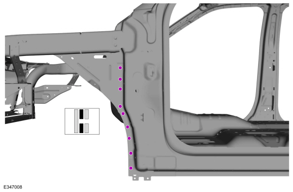
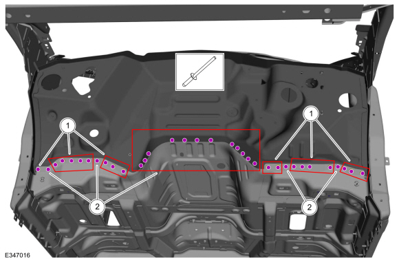
NOTE: Left hand (LH) side shown, right hand (RH) side similar.
NOTE: Flow drill screw (FDS) fasteners are not to be reused. Remove and discard.
On both Sides:
Remove the fasteners.
Use the General Equipment: Self-Piercing Rivet (SPR) Remover/Installer
Use the General Equipment: Belt Sander
Use the General Equipment: Polydrive Bit Socket
 |
-
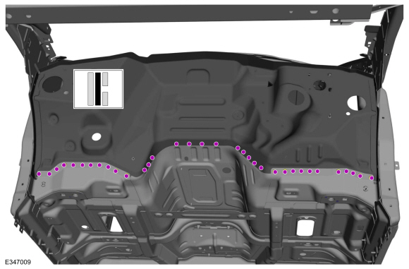
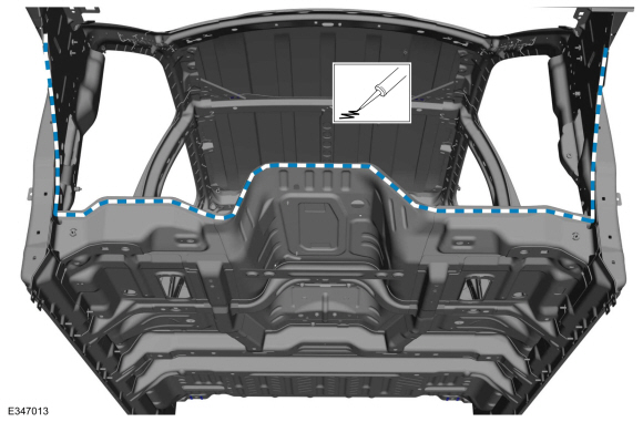
NOTE: Flow drill screw (FDS) fasteners are not to be reused. Remove and discard.
Remove the fasteners.
Use the General Equipment: Self-Piercing Rivet (SPR) Remover/Installer
Use the General Equipment: Belt Sander
Use the General Equipment: Polydrive Bit Socket
 |
-
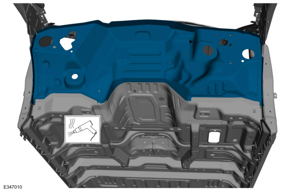
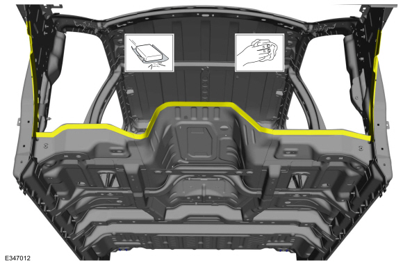
NOTE: Pay particular attention to the location of noise, vibration and harshness (NVH) material, adhesive and sealer used to aid in installation.
Remove the dash panel.
Use the General Equipment: Hot Air Gun
 |
Installation
NOTE: Self-Piercing Rivet (SPR) fasteners may not be placed directly over original self-piercing rivet (SPR) fastener location. They must be placed adjacent to original location matching original quantity.
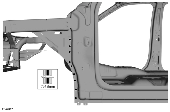
NOTE: Blind or solid rivets may be used in place of self-piercing rivet (SPR) fasteners in the original self-piercing rivet (SPR) fasteners location after enlarging hole to 6.5 mm.
NOTE: Adequately protect all adjacent areas against cutting and grinding and sanding procedures.
-
80-120 Grit Sand Paper:
Sand to remove e-coat and clean.
 |
-
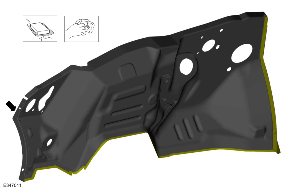
80-120 Grit Sand Paper:
Sand to remove old adhesive, paint and clean.
 |
-
Apply adhesive.
Material: Metal Bonding Adhesive / TA-1, TA-1-B, 3M™ 08115, LORD Fusor® 108B, Henkel Teroson EP 5055
 |
-
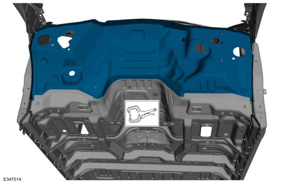
Install, properly position and clamp the dash panel.
Use the General Equipment: Locking Pliers
 |
-
Drill for fasteners.
Use the General Equipment: 6.5 mm Drill Bit
 |
-
Install the fasteners.
Use the General Equipment: Rivet GunItem SPR Number SPR Code Henrob®, Car-OLiner®, CMO®, Chief®, Spanesi®, Wielander and Schill® Mandrel Pro-Spot® Mandrel Blind Rivet Solid Rivet Rivnut® 1 - - - - W708777-S900C - - 2 - - - - W707639-S900C - -
 |
-
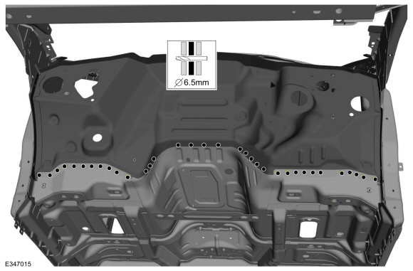
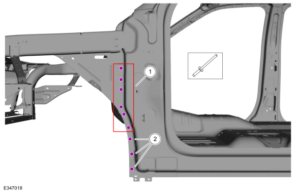
NOTE: Left hand (LH) side shown, right hand (RH) side similar.
Drill for fasteners.
Use the General Equipment: 6.5 mm Drill Bit
 |
-
Install the fasteners.
Use the General Equipment: Rivet GunItem SPR Number SPR Code Henrob®, Car-OLiner®, CMO®, Chief®, Spanesi®, Wielander and Schill® Mandrel Pro-Spot® Mandrel Blind Rivet Solid Rivet Rivnut® 1 - - - - W708777-S900C - - 2 - - - - W702554-S900C - -
 |
-
Install the cowl panel.
Refer to: Cowl Panel (501-27 Front End Sheet Metal Repairs, Removal and Installation).
-
All seams must be sealed to production level.
Material: Seam Sealer / TA-2-B, 3M™ 08308, LORD Fusor® 803DTM
-
Refinish the entire repair using a Ford approved paint system.
-
Restore corrosion protection.
Refer to: Corrosion Prevention (501-25 Body Repairs - General Information, General Procedures).
-
Install the climate control housing.
Refer to: Climate Control Housing (412-00 Climate Control System - General Information, Removal and Installation).
-
Reposition all wiring harnesses, modules and the carpet to original locations.
-
Install the cab: For body mount torque specifications:
Refer to: Frame and Body Mounting (502-02 Full Frame and Body Mounting, Description and Operation).
-
Install the brake master cylinder and brake pedal bracket.
Refer to: Brake Pedal and Bracket (206-06 Hydraulic Brake Actuation, Removal and Installation).
-
Install the steering column.
Refer to: Steering Column (211-04 Steering Column, Removal and Installation).
-
Install the instrument panel and console.
Refer to: Instrument Panel (501-12 Instrument Panel and Console, Removal and Installation).
Refer to: Floor Console (501-12 Instrument Panel and Console, Removal and Installation).
-
On Both Sides:
Install the A-pillar trim panel.
Refer to: A-Pillar Trim Panel (501-05 Interior Trim and Ornamentation, Removal and Installation).
-
On Both Sides:
Install the front seat.
Refer to: Front Seat Track (501-10A Front Seats, Removal and Installation).
Refer to: Front Seat (501-10A Front Seats, Removal and Installation).
-
On Both Sides:
Install the fender and splash shield.
Refer to: Fender (501-02 Front End Body Panels, Removal and Installation).
Refer to: Fender Splash Shield (501-02 Front End Body Panels, Removal and Installation).
-
On Both Sides:
Install the headlamp assembly.
Refer to: Headlamp Assembly (417-01 Exterior Lighting, Removal and Installation).
-
Install and align the hood.
Refer to: Hood (501-02 Front End Body Panels, Removal and Installation).
Refer to: Hood Alignment (501-03 Body Closures, General Procedures).
-
Install the front bumper.
Refer to: Front Bumper (501-19 Bumpers, Removal and Installation).
Refer to: Front Bumper Cover (501-19 Bumpers, Removal and Installation).
-
Repower the SRS .
Refer to: Supplemental Restraint System (SRS) Repowering (501-20B Supplemental Restraint System, General Procedures).

 Fender Apron Panel Reinforcement. Removal and Installation
Special Tool(s) /
General Equipment
6.5 mm Drill Bit
Polydrive Bit Socket
Self-Piercing Rivet (SPR) Remover/Installer
Belt Sander
Blind Rivet Gun
Hot Air Gun
Locking Pliers
Materials
Name
Specification
Metal Bonding AdhesiveTA-1, TA-1-B, 3M™ 08115, LORD Fusor® 108B, Henkel Teroson EP 5055
-
Seam S..
Other information:
Lincoln Navigator 2018-2026 Workshop Manual: Transmission Cooling - Component Location. Description and Operation
Item Description 1 Transmission fluid heater coolant control valve 2 Transmission fluid heat exchanger coolant inlet hose 3 Transmission fluid heat exchanger coolant outlet hose 4 Transmission fluid heat exchanger ..
Lincoln Navigator 2018-2026 Workshop Manual: Hydraulic Brake Actuation - System Operation and Component Description. Description and Operation
System Operation System Diagram – Adjustable Pedals *.sttxt { visibility: hidden; } *.stcallout { visibility: visible; } 1 Adjustable Pedal Motor E344587 2 RKE ..
Categories
- Manuals Home
- 4th Gen Lincoln Navigator Service Manual (2018 - 2026)
- Body Control Module (BCM). Removal and Installation
- Head Up Display (HUD) Module Calibration. General Procedures
- Front Bumper Cover. Removal and Installation
- SYNC Module [APIM]. Removal and Installation
- Rear View Mirrors - System Operation and Component Description. Description and Operation
Diagnostic Methods. Description and Operation
This document provides critical diagnostic knowledge required for successful repair outcomes. It identifies technical competencies expected by users of this manual.
Ford Diagnostic Assumptions
Ford diagnostics assume the vehicle concern described by the test title is currently present. Exceptions to this rule are noted in each test. Do not replace modules or other components as directed by a diagnostic if the concern is not present at the time of testing.