Lincoln Navigator: Front End Sheet Metal Repairs / Fender Apron Panel Reinforcement. Removal and Installation
Special Tool(s) / General Equipment
| 6.5 mm Drill Bit | |
| Polydrive Bit Socket | |
| Self-Piercing Rivet (SPR) Remover/Installer | |
| Belt Sander | |
| Blind Rivet Gun | |
| Hot Air Gun | |
| Locking Pliers |
Materials
| Name | Specification |
|---|---|
| Metal Bonding Adhesive TA-1, TA-1-B, 3M™ 08115, LORD Fusor® 108B, Henkel Teroson EP 5055 |
- |
| Seam Sealer TA-2-B, 3M™ 08308, LORD Fusor® 803DTM |
- |
Removal
NOTE: Aluminum body panels are highly receptive to heat transfer. With the extensive use of structural adhesives and non-structural sealers used in vehicle construction, the potential of heat transfer could impact adhesives and sealers in non-associated panels during the repair process. Many repairs areas that utilize structural adhesive may be separated after fastener removal by using a panel chisel along the joint/flange. Using heat not exceeding 425° F to loosen a bonded panel should only be done when all panels in the joint will be replaced and new adhesive applied.
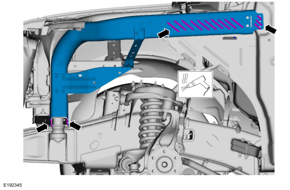
NOTE: The fender apron panel reinforcement must be replaced at the factory seams. No sectioning procedure is approved or permitted.
NOTE: The fender apron panel reinforcement is made of hydro-formed HSLA (High-Strength Low Alloy) steel and may be separated at weld joints. The following assumes full component replacement. Adjust to meet repair needs.
NOTE: LH side shown, RH side similar.
-
Depower the SRS .
Refer to: Supplemental Restraint System (SRS) Depowering (501-20B Supplemental Restraint System, General Procedures).
-
Remove the air cleaner.
Refer to: Air Cleaner (303-12 Intake Air Distribution and Filtering - 3.5L EcoBoost (272kW/370PS), Removal and Installation).
-
Remove the battery.
Refer to: Battery (414-01 Battery, Mounting and Cables, Removal and Installation).
-
Remove the fender and splash shield.
Refer to: Fender (501-02 Front End Body Panels, Removal and Installation).
Refer to: Fender Splash Shield (501-02 Front End Body Panels, Removal and Installation).
-
Remove the front door.
Refer to: Front Door (501-03 Body Closures, Removal and Installation).
-
Remove the hood and the hood hinges.
Refer to: Hood (501-02 Front End Body Panels, Removal and Installation).
-
Remove the cowl panel grille and cowl panel.
Refer to: Cowl Panel Grille (501-02 Front End Body Panels, Removal and Installation).
Refer to: Cowl Panel (501-02 Front End Body Panels, Removal and Installation).
-
Remove the front bumper.
Refer to: Front Bumper (501-19 Bumpers, Removal and Installation).
-
Remove the cooling module.
Refer to: Cooling Module (303-03 Engine Cooling - 3.5L EcoBoost (272kW/370PS), Removal and Installation).
-
If Required:
Dimensionally restore the vehicle to pre-damage condition..
Refer to: Body and Frame (501-26 Body Repairs - Vehicle Specific Information and Tolerance Checks, Description and Operation).
-
Position aside all modules and wiring harnesses.
-
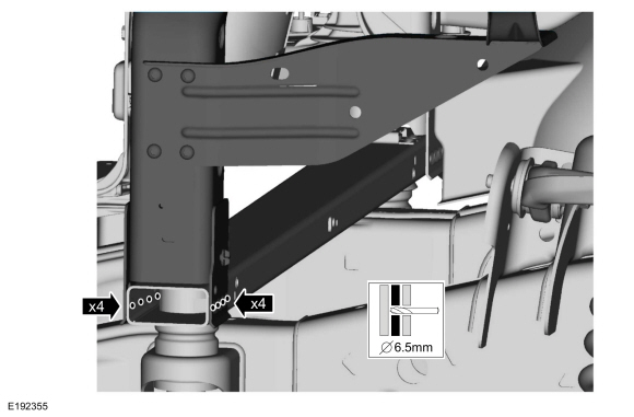
Remove and discard the FDS fasteners.
Use the General Equipment: Polydrive Bit Socket
 |
-
Remove the bolts.
 |
-
Remove the SPR fasteners.
Use the General Equipment: Self-Piercing Rivet (SPR) Remover/Installer
Use the General Equipment: Belt Sander
 |
-
Remove and discard the FDS and SPR fasteners.
 |
-
NOTE: Aluminum body panels are highly receptive to heat transfer. With the extensive use of structural adhesives and non-structural sealers used in vehicle construction, the potential of heat transfer could impact adhesives and sealers in non-associated panels during the repair process. Many repairs areas that utilize structural adhesive may be separated after fastener removal by using a panel chisel along the joint/flange. Using heat not exceeding 425° F to loosen a bonded panel should only be done when all panels in the joint will be replaced and new adhesive applied.
Break the adhesive bond and remove the fender apron panel reinforcement.
Use the General Equipment: Hot Air Gun
 |
Installation
NOTE: The fender apron panel reinforcement must be replaced at the factory seams. No sectioning procedure is approved or permitted.
NOTE: The fender apron panel reinforcement is made of hydro-formed HSLA (High-Strength Low Alloy) steel and may be separated at weld joints. The following assumes full component replacement. Adjust to meet repair needs.
NOTE: SPR fasteners may not be placed directly over original SPR location. They must be placed adjacent to original location matching original quantity.
NOTE: LH side shown, RH side similar.
-
80-120 Grit Sand Paper:
Sand to remove old adhesive and clean.
 |
-
80-120 Grit Sand Paper:
Sand to remove e-coat and clean.
 |
-
Apply adhesive.
Material: Metal Bonding Adhesive / TA-1, TA-1-B, 3M™ 08115, LORD Fusor® 108B, Henkel Teroson EP 5055
 |
-
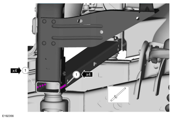
Install, properly position and clamp the fender apron panel reinforcement.
Use the General Equipment: Locking Pliers
 |
-
Install the bolts.
Torque: 22 lb.ft (30 Nm)
|
-
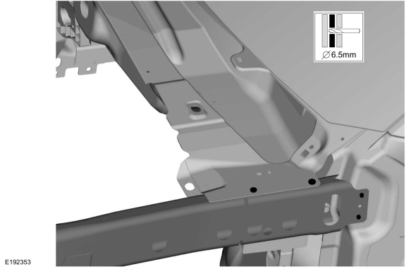
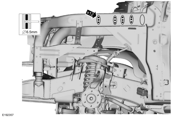
Drill for fasteners.
Use the General Equipment: 6.5 mm Drill Bit
 |
-
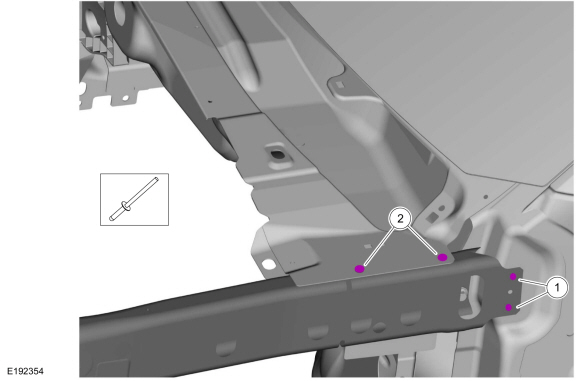
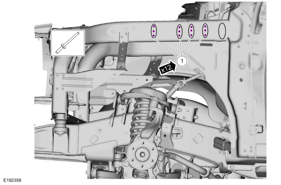
Install blind rivet fasteners.
Use the General Equipment: Blind Rivet GunItem SPR Number SPR Code Henrob®, Car-O-Liner ®, CMO®, Chief®, Spanesi®, Wielander and Schill® Mandrel Pro-Spot® Mandrel Blind Rivet Solid Rivet Rivenut® 1 - - - - W708777-S900C - - 2 - - - - W702512-S900C - -
 |
-
Drill for fasteners.
Use the General Equipment: 6.5 mm Drill Bit
 |
-
Install blind rivet fasteners.
Use the General Equipment: Blind Rivet GunItem SPR Number SPR Code Henrob®, Car-O-Liner ®, CMO®, Chief®, Spanesi®, Wielander and Schill® Mandrel Pro-Spot® Mandrel Blind Rivet Solid Rivet Rivenut® 1 - - - - W708777-S900C - -
 |
-
Seam Sealing:
All seams must be sealed to production level.
Material: Seam Sealer / TA-2-B, 3M™ 08308, LORD Fusor® 803DTM
-
Refinish the repair using a Ford approved paint system.
-
Restore corrosion protection.
Refer to: Corrosion Prevention (501-25 Body Repairs - General Information, General Procedures).
-
Reposition all modules and wiring harnesses to original locations.
-
Install the cooling module.
Refer to: Cooling Module (303-03 Engine Cooling - 3.5L EcoBoost (272kW/370PS), Removal and Installation).
-
Install the front bumper.
Refer to: Front Bumper (501-19 Bumpers, Removal and Installation).
Refer to: Front Bumper Cover (501-19 Bumpers, Removal and Installation).
-
Install the cowl panel grille and cowl panel.
Refer to: Cowl Panel (501-02 Front End Body Panels, Removal and Installation).
Refer to: Cowl Panel Grille (501-02 Front End Body Panels, Removal and Installation).
-
Install the hood and the hood hinges.
Refer to: Hood (501-02 Front End Body Panels, Removal and Installation).
-
Install the front door.
Refer to: Front Door (501-03 Body Closures, Removal and Installation).
-
Install the fender and splash shield.
Refer to: Fender (501-02 Front End Body Panels, Removal and Installation).
Refer to: Fender Splash Shield (501-02 Front End Body Panels, Removal and Installation).
-
Install the battery.
Refer to: Battery (414-01 Battery, Mounting and Cables, Removal and Installation).
-
Install the air cleaner.
Refer to: Air Cleaner (303-12 Intake Air Distribution and Filtering - 3.5L EcoBoost (272kW/370PS), Removal and Installation).
-
Repower the SRS .
Refer to: Supplemental Restraint System (SRS) Repowering (501-20B Supplemental Restraint System, General Procedures).

 Radiator Support Assembly. Removal and Installation
Special Tool(s) /
General Equipment
6.5 mm Drill Bit
Polydrive Bit Socket
Rivet Gun
Self-Piercing Rivet (SPR) Remover/Installer
Belt Sander
Hot Air Gun
Materials
Name
Specification
Seam SealerTA-2-B, 3M™ 08308, LORD Fusor® 803DTM
-
Removal
NOTE:
Aluminum body panels are highly receptive to heat tra..
Other information:
Lincoln Navigator 2018-2026 Workshop Manual: Brake Service Mode Activation and Deactivation. General Procedures
Activation WARNING: Service actions on vehicles equipped with electronic parking brakes may cause unexpected parking brake application, which could result in injury to hands or fingers. Put the electronic parking brake system into service mode prior to servicing or removing rear brake components. Failure to follow this instruction may result in serious personal injury. ..
Lincoln Navigator 2018-2026 Workshop Manual: Information and Entertainment System - System Operation and Component Description. Description and Operation
System Operation Audio System Overview NOTE: Refer to the Owner Literature for additional details of the audio system. AM / FM Radio The ACM can operate when the ignition is on or off. The accessory delay feature powers the audio system, after the ignition has been turned off, for a preset time or until a front door is opened. The ACM is connected to the vehicle netw..
Categories
- Manuals Home
- 4th Gen Lincoln Navigator Service Manual (2018 - 2026)
- Vehicle Dynamics Control Module (VDM). Removal and Installation
- Liftgate Trim Panel. Removal and Installation
- Remote Function Actuator (RFA) Module. Removal and Installation
- SYNC Module [APIM]. Removal and Installation
- Windshield Washer Pump. Removal and Installation
Front Stabilizer Bar Link. Removal and Installation
Removal
NOTICE: Suspension fasteners are critical parts that affect the performance of vital components and systems. Failure of these fasteners may result in major service expense. Use the same or equivalent parts if replacement is necessary. Do not use a replacement part of lesser quality or substitute design. Tighten fasteners as specified.
NOTE: Removal steps in this procedure may contain installation details.
With the vehicle in NEUTRAL, position it on a hoist.Refer to: Jacking and Lifting (100-02 Jacking and Lifting, Description and Operation).
NOTICE: Do not use power tools to remove or install the stabilizer bar