Lincoln Navigator: Rear End Sheet Metal Repairs / Rear Wheelhouse. Removal and Installation
Special Tool(s) /
General Equipment
| 6.5 mm Drill Bit |
| Spherical Cutter |
| Self-Piercing Rivet (SPR) Remover/Installer |
| Belt Sander |
| Blind Rivet Gun |
| Air Body Saw |
| MIG/MAG Welding Equipment |
| Locking Pliers |
Materials
| Name |
Specification |
Metal Bonding Adhesive
TA-1, TA-1-B, 3M™ 08115, LORD Fusor® 108B, Henkel Teroson EP 5055 |
-
|
Seam Sealer
TA-2-B, 3M™ 08308, LORD Fusor® 803DTM |
-
|
Flexible Foam Repair
3M™ 08463, LORD Fusor® 121 |
-
|
Removal
NOTICE:
Bodyside sectioning is prohibited within 50 mm of door hinge, door striker and restraints anchoring points.
NOTE:
The wheelhouse outer panel may be sectioned for repair using
a backer plate, adhesive and blind rivets. The following steps assume
full component replacement. Adjust to meet repair needs.
NOTE:
SPR fasteners may not be placed directly over original SPR location.
They must be placed adjacent to original location matching original
quantity.
NOTE:
LH side shown, RH side similar.
NOTE:
Aluminum body panels are highly receptive to heat transfer.
With the extensive use of structural adhesives and non-structural
sealers used in vehicle construction, the potential of heat transfer
could impact adhesives and sealers in non-associated panels during the
repair process. Many repairs areas that utilize structural adhesive may
be separated after fastener removal by using a panel chisel along the
joint/flange. Using heat not exceeding 425° F to loosen a bonded panel
should only be done when all panels in the joint will be replaced and
new adhesive applied.
NOTE:
LH side shown, RH side shown.
-
Remove the liftgate.
Refer to: Liftgate (501-03 Body Closures, Removal and Installation).
-
Remove the C-pillar trim panel.
Refer to: C-Pillar Trim Panel (501-05 Interior Trim and Ornamentation, Removal and Installation).
-
Remove the loadspace interior trim.
Refer to: Loadspace Trim Panel (501-05 Interior Trim and Ornamentation, Removal and Installation).
-
Remove the wheel and tire on the affected side.
Refer to: Wheel and Tire (204-04A Wheels and Tires, Removal and Installation).
-
Remove the quarter panel.
Refer to: Quarter Panel (501-30 Rear End Sheet Metal Repairs, Removal and Installation).
-
Remove the wheel opening splash shield.
-
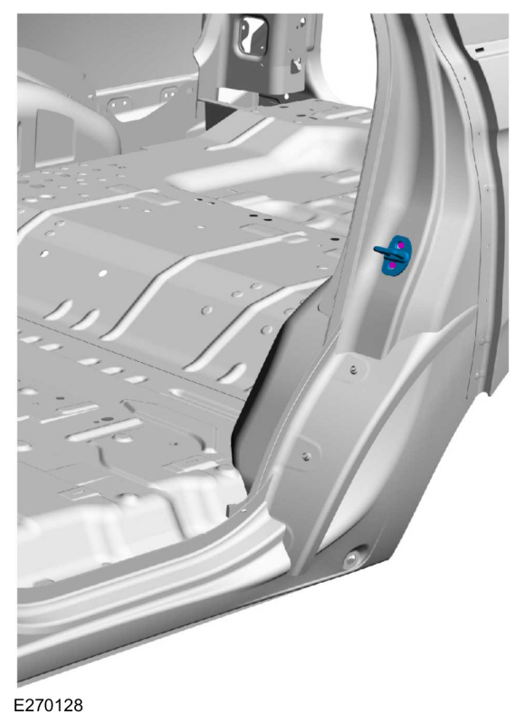
Remove the rear door striker.
-
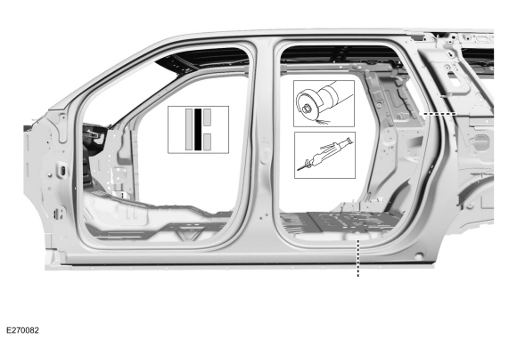
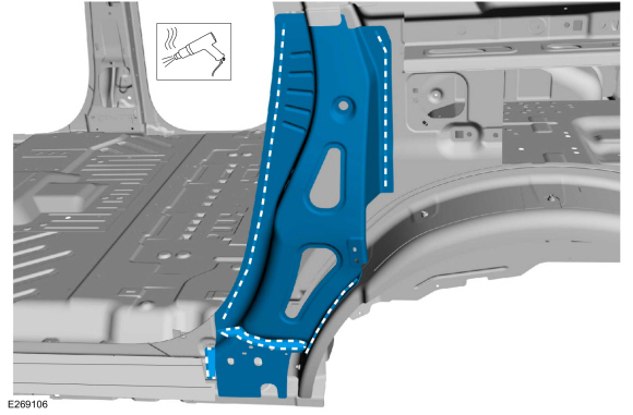
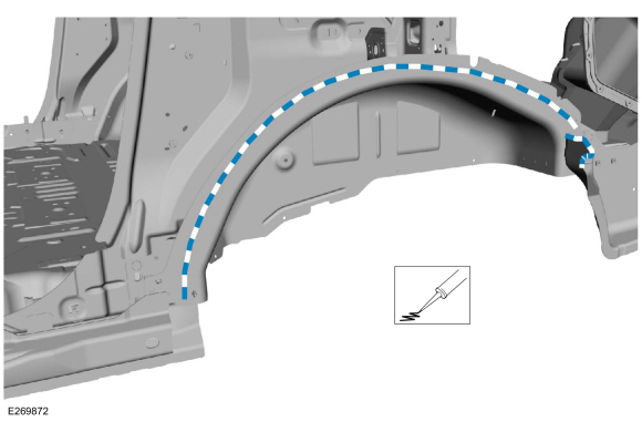
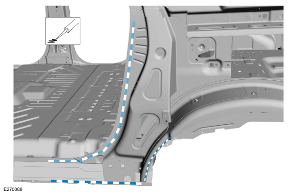
Cut section of the rear dear opening panel outer layer only as indicated.
Use the General Equipment: Air Body Saw
Use the General Equipment: Spherical Cutter
-
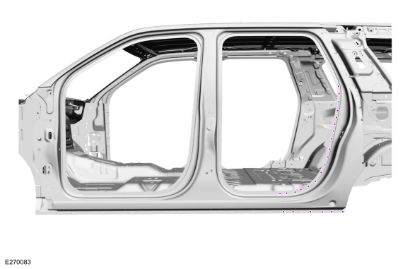
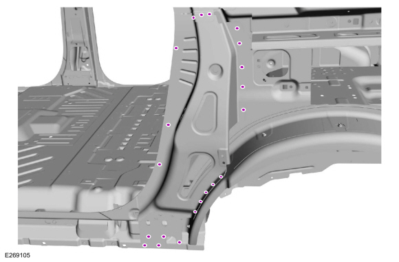
Remove the rivet fasteners from the rear door opening panel.
Use the General Equipment: Self-Piercing Rivet (SPR) Remover/Installer
Use the General Equipment: Belt Sander
-
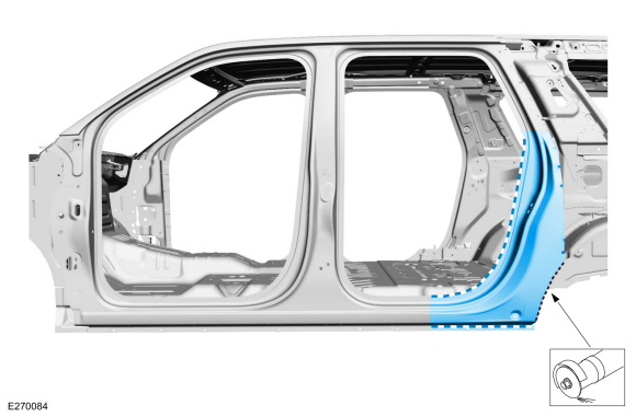
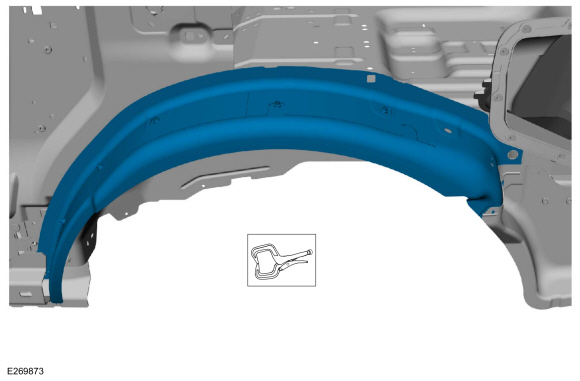
Break the adhesive bond, remove the wheel opening flange material and remove the door opening panel section.
Use the General Equipment: Spherical Cutter
-
Position aside the roof opening panel water drain tube, if equipped.
-
Remove the C-pillar lower reinforcement fasteners.
Use the General Equipment: Self-Piercing Rivet (SPR) Remover/Installer
Use the General Equipment: Belt Sander
-
NOTE:
Long wheelbase (LWB) shown, short wheelbase (SWB) similar.
Note NVH foam locations when removing panel.
Break the adhesive bond and remove the C-pillar lower reinforcement.
-
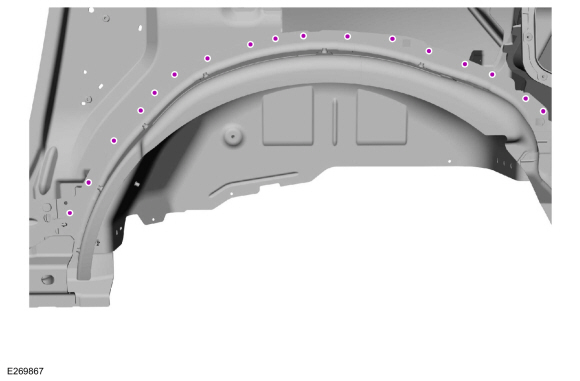
Remove the fasteners.
Use the General Equipment: Self-Piercing Rivet (SPR) Remover/Installer
Use the General Equipment: Belt Sander
-
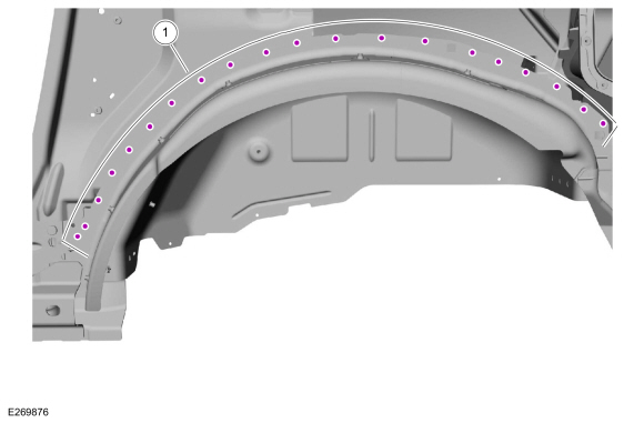
Remove the upper flange fasteners.
Use the General Equipment: Self-Piercing Rivet (SPR) Remover/Installer
Use the General Equipment: Belt Sander
-
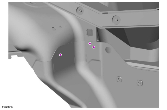
Remove the fasteners.
Use the General Equipment: Self-Piercing Rivet (SPR) Remover/Installer
Use the General Equipment: Belt Sander
-
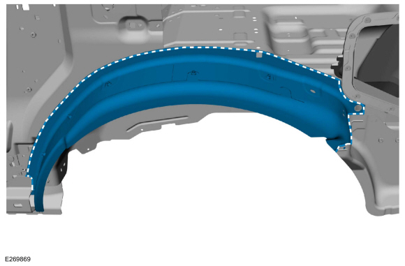
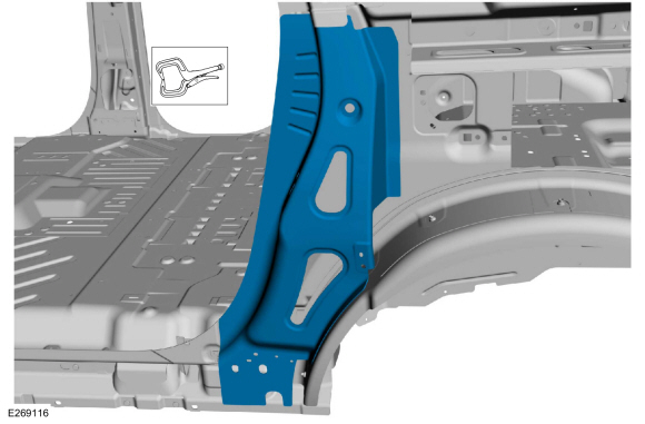
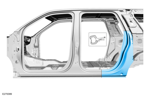
Break the adhesive and sealer bond and remove the outer wheelhouse panel.
Installation
NOTE:
Aluminum body panels are highly receptive to heat transfer.
With the extensive use of structural adhesives and non-structural
sealers used in vehicle construction, the potential of heat transfer
could impact adhesives and sealers in non-associated panels during the
repair process. Many repairs areas that utilize structural adhesive may
be separated after fastener removal by using a panel chisel along the
joint/flange. Using heat not exceeding 425° F to loosen a bonded panel
should only be done when all panels in the joint will be replaced and
new adhesive applied.
NOTE:
SPR fasteners may not be placed directly over original SPR location.
They must be placed adjacent to original location matching original
quantity.
NOTE:
Blind or solid rivet fasteners may be used in place of SPR fasteners after enlarging holes to 6.5 mm.
-
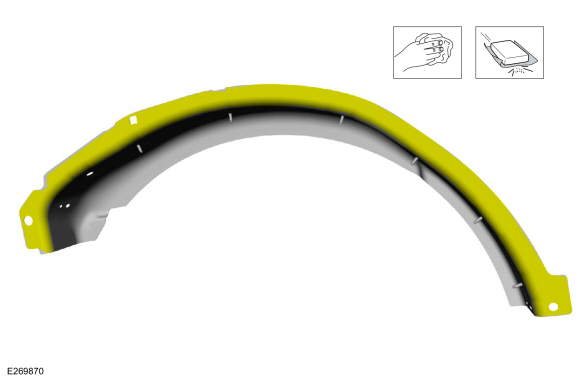
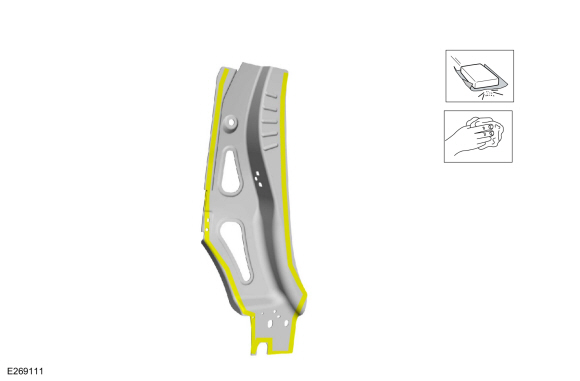
Sand to remove e-coating using 80-120 grit sandpaper on the replacement panel.
-
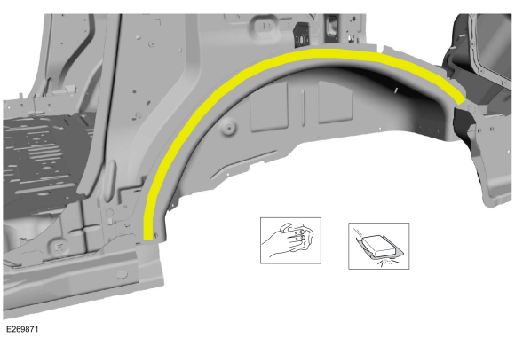
Sand inner wheelhouse mating surface using 80-120 grit sandpaper.
-
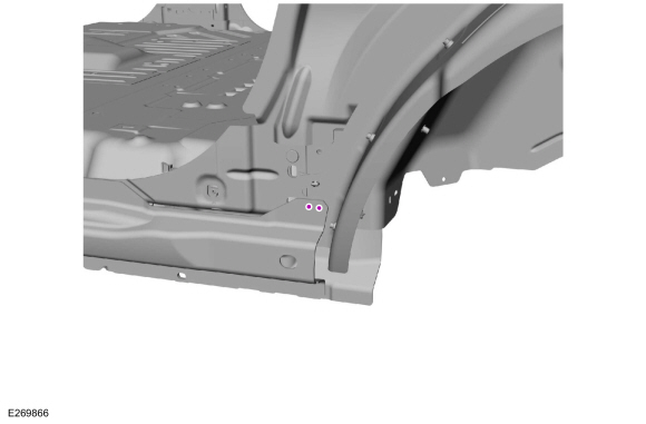
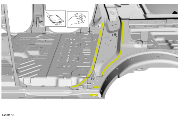
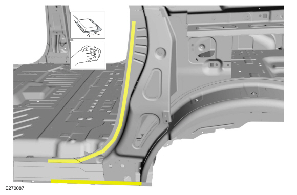
Apply adhesive and NVH foam as indicated.
Material: Metal Bonding Adhesive
/ TA-1, TA-1-B, 3M™ 08115, LORD Fusor® 108B, Henkel Teroson EP 5055
Material: Flexible Foam Repair
/ 3M™ 08463, LORD Fusor® 121
-
Install and clamp the wheelhouse panel in position.
Refer to: Joining Techniques (501-25 Body Repairs - General Information, General Procedures).
Use the General Equipment: Locking Pliers
-
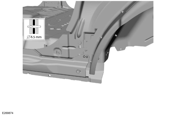
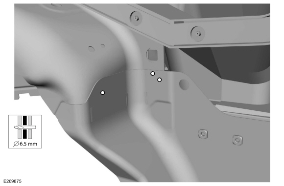
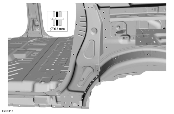
Drill for rivets.
Use the General Equipment: 6.5 mm Drill Bit
-
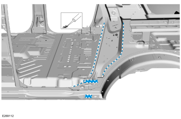
Install blind rivet fasteners.
|
Item
|
SPR Number
|
SPR Code
|
Henrob® Mandrel
|
Pro-Spot® Mandrel
|
Blind Rivet
|
Solid Rivet
|
Rivnut®
|
|
1
|
-
|
-
|
-
|
-
|
W708777-S900C
|
-
|
-
|
Use the General Equipment: Blind Rivet Gun
-
Install rivet fasteners.
|
Item
|
SPR Number
|
SPR Code
|
Henrob® Mandrel
|
Pro-Spot® Mandrel
|
Blind Rivet
|
Solid Rivet
|
Rivnut®
|
|
1
|
-
|
-
|
-
|
-
|
W702554-S900C
|
-
|
-
|
-
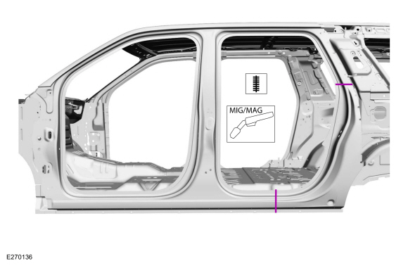
Drill for MIG plug welds.
Use the General Equipment: 6.5 mm Drill Bit
-
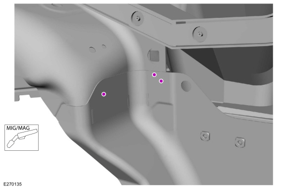
Install MIG plug welds.
Use the General Equipment: MIG/MAG Welding Equipment
-
Sand and clean the mating surface using 80-120 grit sandpaper.
-
Sand and clean the mating surface using 80-120 grit sandpaper.
-
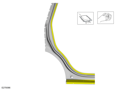
Apply adhesive and NVH foam as indicated.
Material: Metal Bonding Adhesive
/ TA-1, TA-1-B, 3M™ 08115, LORD Fusor® 108B, Henkel Teroson EP 5055
Material: Flexible Foam Repair
/ 3M™ 08463, LORD Fusor® 121
-
Install and clamp the C-pillar lower reinforcement panel.
Use the General Equipment: Locking Pliers
-
Drill for blind rivet fasteners.
Use the General Equipment: 6.5 mm Drill Bit
-
NOTE:
SPR fasteners may be replaced with solid rivets or blind rivet fasteners after enlarging hole to 6.5 mm.
NOTE:
SPR
fasteners may not be placed directly over original location. They must
equal original quantity and be placed adjacent to original location.
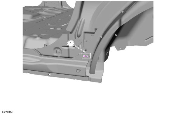
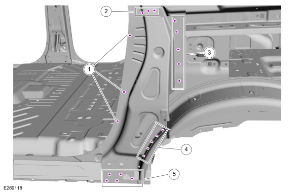
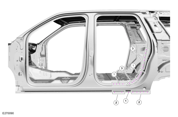
Install rivet fasteners.
|
Item
|
SPR Number
|
SPR Code
|
Henrob® Mandrel
|
Pro-Spot® Mandrel
|
Blind Rivet
|
Solid Rivet
|
Rivnut®
|
|
1
|
W712218-S900
|
DB
|
DZ09-025/H
|
SA-0400/SA-0401
|
W702512-S900C
|
W790376-S900
|
-
|
|
2
|
-
|
-
|
-
|
-
|
W702512-S900C
|
-
|
-
|
|
3
|
-
|
-
|
-
|
-
|
W702512-S900C
|
-
|
-
|
|
4
|
-
|
-
|
|
-
|
W707638-S900C
|
-
|
-
|
|
5
|
-
|
-
|
-
|
-
|
W08777-S900C
|
-
|
-
|
Use the General Equipment: Self-Piercing Rivet (SPR) Remover/Installer
-
Cut section from the service panel to fit repair.
Use the General Equipment: Spherical Cutter
Use the General Equipment: Air Body Saw
-
Sand to remove e-coating on flanges of replacement section.
-
Sand to remove old adhesive on mating surfaces.
-
Apply adhesive and NVH foam to mating surfaces as indicated.
Material: Metal Bonding Adhesive
/ TA-1, TA-1-B, 3M™ 08115, LORD Fusor® 108B, Henkel Teroson EP 5055
Material: Flexible Foam Repair
/ 3M™ 08463, LORD Fusor® 121
-
NOTE:
The use of a backer plate when creating butt weld joints will produce a stronger and more uniform repair.
In butt-weld areas: Create a backer plate
from an unused portion of the old body panel or service replacement
panel and install on the vehicle at each sectioning joint.
Refer to: Joining Techniques (501-25 Body Repairs - General Information, General Procedures).
-
Install and clamp the door opening panel section in position.
Use the General Equipment: Locking Pliers
-
NOTE:
SPR fasteners may be replaced with solid rivets or blind rivet fasteners after enlarging hole to 6.5 mm.
NOTE:
SPR
fasteners may not be placed directly over original location. They must
equal original quantity and be placed adjacent to original location.
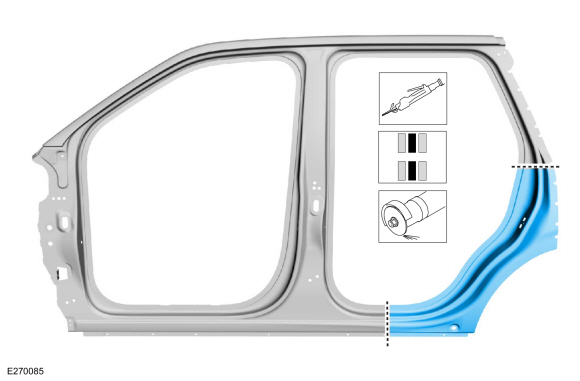
Install fasteners.
|
Item
|
SPR Number
|
SPR Code
|
Henrob® Mandrel
|
Pro-Spot® Mandrel
|
Blind Rivet
|
Solid Rivet
|
Rivnut®
|
|
1
|
W708713-S900
|
AS
|
DZ09-025/H
|
SA-0400/SA-0401
|
-
|
W790376-S900
|
-
|
|
2
|
W717184-S900
|
QA
|
DP10-200/H
|
SA-0400/SA-0402
|
-
|
W790377-S900
|
-
|
|
3
|
W717186-S900
|
EN
|
DP11-200/H
|
SA-0400/SA-0402
|
-
|
W790377-S900
|
-
|
-
Seam weld the sectioning joints.
Use the General Equipment: MIG/MAG Welding Equipment
-
Metal finish the repair using typical aluminum metal finishing techniques and a fiber-based body filler.
Refer to: Special Repair Considerations for Aluminum Repairs (501-25
Body Repairs - General Information, Description and Operation).
-
Seam Sealing:
All areas must be sealed to production level.
Material: Seam Sealer
/ TA-2-B, 3M™ 08308, LORD Fusor® 803DTM
-
Refinish the repair area using a Ford approved paint system and typical refinishing techniques.
-
Install the quarter panel.
Refer to: Quarter Panel (501-30 Rear End Sheet Metal Repairs, Removal and Installation).
-
Install the wheel opening splash shield.
-
Install the C-pillar trim panel.
Refer to: C-Pillar Trim Panel (501-05 Interior Trim and Ornamentation, Removal and Installation).
-
Install the loadspace interior trim.
Refer to: Loadspace Trim Panel (501-05 Interior Trim and Ornamentation, Removal and Installation).
-
Install the wheel and tire on the affected side.
Refer to: Wheel and Tire (204-04A Wheels and Tires, Removal and Installation).
-
Install the rear door striker.
Torque:
Striker :
18 lb.ft (25 Nm)
-
Install the rear door scuff plate and door opening weather strip.
-
Install the liftgate and align as necessary.
Refer to: Liftgate (501-03 Body Closures, Removal and Installation).
Refer to: Liftgate Alignment (501-03 Body Closures, General Procedures).
Special Tool(s) /
General Equipment
6.5 mm Drill Bit
Self-Piercing Rivet (SPR) Remover/Installer
Belt Sander
Blind Rivet Gun
Locking Pliers
Materials
Name
Specification
Metal Bonding AdhesiveTA-1, TA-1-B, 3M™ 08115, LORD Fusor® 108B, Henkel Teroson EP 5055
-
Seam SealerTA-2-B, 3M™ 08308, LORD Fusor® 803DTM
-..
Other information:
Removal
NOTE:
LH seat shown, RH seat similar.
NOTE:
Removal steps in this procedure may contain installation details.
Raise the seat to the full up position.
Disconnect the electrical connector.
Remove the screw.
Torque:
8 lb.in (0.9 Nm)
Remove the seat position sens..
Special Tool(s) /
General Equipment
Interior Trim Remover
Removal
NOTE:
Driver seat shown, passenger seat similar.
Remove the front seat.
Refer to: Front Seat (501-10A Front Seats, Removal and Installation).
Release the front seat wiring harness and electrical
connector retainers and position the front seat wiring harnesses asid..

 Water Drain Panel. Removal and Installation