Lincoln Navigator: Rear End Sheet Metal Repairs / Rear Lamp Mounting Panel. Removal and Installation
Special Tool(s) /
General Equipment
| 6.5 mm Drill Bit |
| Polydrive Bit Socket |
| Self-Piercing Rivet (SPR) Remover/Installer |
| Belt Sander |
| Blind Rivet Gun |
| Locking Pliers |
Materials
| Name |
Specification |
Metal Bonding Adhesive
TA-1, TA-1-B, 3M™ 08115, LORD Fusor® 108B, Henkel Teroson EP 5055 |
-
|
Flexible Foam Repair
3M™ 08463, LORD Fusor® 121 |
-
|
Removal
NOTE:
Pay particular attention to location of NVH sealers and adhesives during removal to aid in installation.
NOTE:
Aluminum body panels are highly receptive to heat transfer.
With the extensive use of structural adhesives and non-structural
sealers used in vehicle construction, the potential of heat transfer
could impact adhesives and sealers in non-associated panels during the
repair process. Many repairs areas that utilize structural adhesive may
be separated after fastener removal by using a panel chisel along the
joint/flange. Using heat not exceeding 425° F to loosen a bonded panel
should only be done when all panels in the joint will be replaced and
new adhesive applied.
NOTE:
LH side shown, RH side similar.
-
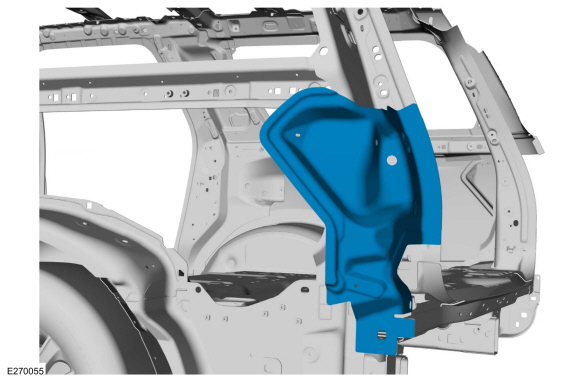
Remove the drain panel.
Refer to: Water Drain Panel (501-30 Rear End Sheet Metal Repairs, Removal and Installation).
-
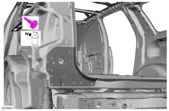
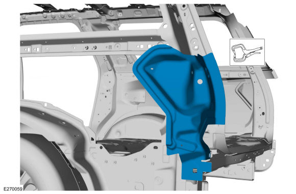
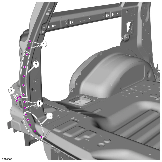
Remove and discard the FDS fasteners.
Use the General Equipment: Polydrive Bit Socket
-
Remove the fasteners.
Use the General Equipment: Self-Piercing Rivet (SPR) Remover/Installer
Use the General Equipment: Belt Sander
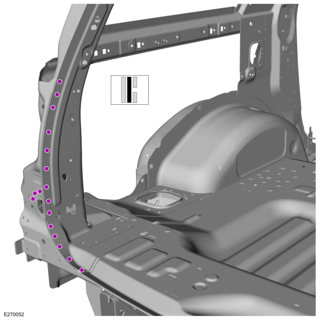
-
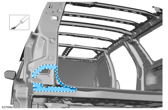
Remove the closeout panel.
-
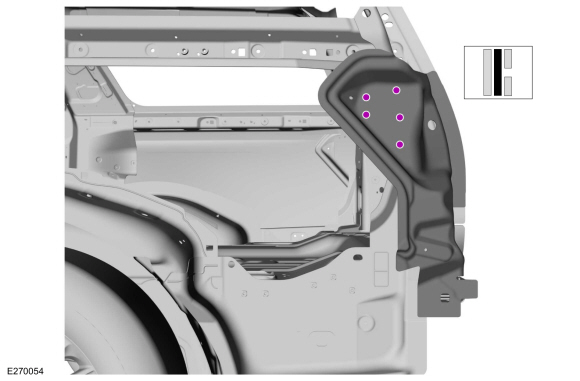
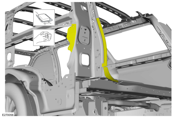
Remove the fasteners.
Use the General Equipment: Self-Piercing Rivet (SPR) Remover/Installer
Use the General Equipment: Belt Sander
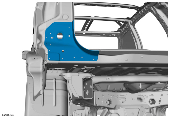
-
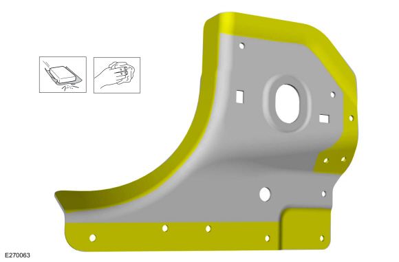
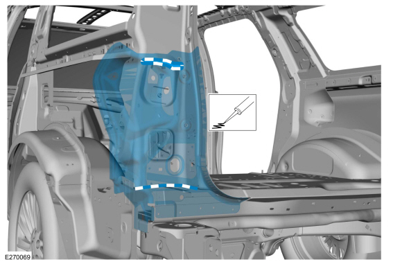
Remove the lamp panel.
Installation
NOTE:
SPR fasteners may not be placed directly over original SPR location.
They must be placed adjacent to original location matching original
quantity.
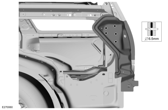
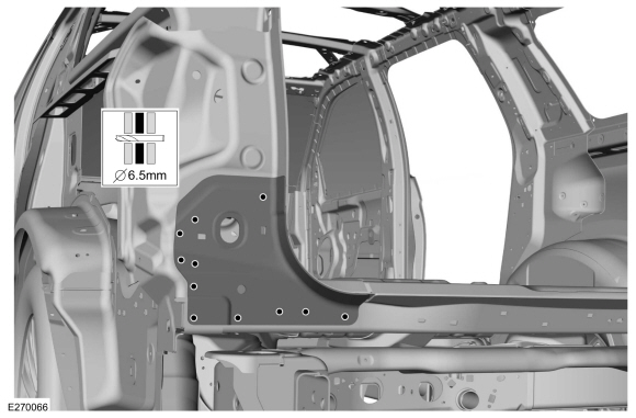
NOTE:
Blind or solid rivet fasteners may be used in place of SPR fasteners
after enlarging holes to 6.5 mm. Blind or sold rivets must equal
original fasteners in both location and quantity.
-
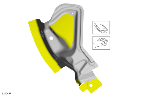
80-120 grit sandpaper.
Sand to remove old adhesive and sealer and clean.
-
80-120 grit sandpaper.
Sand to remove e-coat and clean.
-
Apply adhesive.
Material: Metal Bonding Adhesive
/ TA-1, TA-1-B, 3M™ 08115, LORD Fusor® 108B, Henkel Teroson EP 5055
-
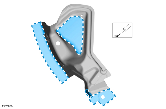
Install, properly position and clamp.
Use the General Equipment: Locking Pliers
-
Drill for fasteners.
Use the General Equipment: 6.5 mm Drill Bit
-
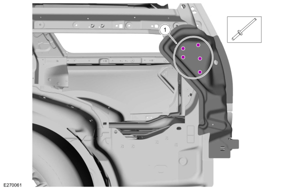
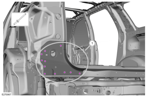
Install fasteners.
|
Item
|
SPR Number
|
SPR code
|
Henrob®, Car-O-Liner ®, CMO®, Chief®, Spanesi®, Wielander and Schill® Mandrel
|
Pro-Spot® Mandrel
|
Blind Rivet
|
Solid Rivet
|
Rivnut®
|
|
1
|
-
|
-
|
-
|
-
|
W708777-S900C
|
-
|
-
|
Use the General Equipment: Blind Rivet Gun
-
80-120 grit sandpaper.
Sand to remove old adhesive and e-coat and clean.
-
80-120 grit sandpaper.
Sand to remove e-coat and clean.
-
Apply adhesive.
Material: Metal Bonding Adhesive
/ TA-1, TA-1-B, 3M™ 08115, LORD Fusor® 108B, Henkel Teroson EP 5055
-
Install, properly position and clamp.
Use the General Equipment: Locking Pliers
-
Drill for fasteners.
Use the General Equipment: 6.5 mm Drill Bit
-
Install fasteners.
|
Item
|
SPR Number
|
SPR Code
|
Henrob®, Car-O-Liner ®, CMO®, Chief®, Spanesi®, Wielander and Schill® Mandrel
|
Pro-Spot® Mandrel
|
Blind Rivet
|
Solid Rivet
|
Rivnut®
|
|
1
|
-
|
-
|
-
|
-
|
W708777-S900C
|
-
|
-
|
Use the General Equipment: Blind Rivet Gun
-
Install fasteners.
|
Item
|
SPR Number
|
SPR code
|
Henrob®, Car-O-Liner ®, CMO®, Chief®, Spanesi®, Wielander and Schill® Mandrel
|
Pro-Spot® Mandrel
|
Blind Rivet
|
Solid Rivet
|
Rivnut®
|
|
1
|
W717182-S900
|
QC
|
DP10-200/H
|
SA-0400/SA-0402
|
-
|
W708777-S900
|
-
|
|
2
|
-
|
-
|
-
|
-
|
W708777-S900C
|
-
|
-
|
|
3
|
W712218-S900
|
DB
|
DP09-025/H
|
SA-0400/SA-0401
|
-
|
W708776-S900
|
-
|
Use the General Equipment: Self-Piercing Rivet (SPR) Remover/Installer
Use the General Equipment: Blind Rivet Gun
-
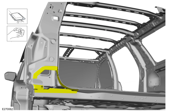
Install NVH foam in areas noted during removal.
Material: Flexible Foam Repair
/ 3M™ 08463, LORD Fusor® 121
-
Install the drain panel.
Refer to: Water Drain Panel (501-30 Rear End Sheet Metal Repairs, Removal and Installation).
Special Tool(s) /
General Equipment
6.5 mm Drill Bit
Spherical Cutter
Self-Piercing Rivet (SPR) Remover/Installer
Belt Sander
Blind Rivet Gun
Air Body Saw
MIG/MAG Welding Equipment
Locking Pliers
Materials
Name
Specification
Metal Bonding AdhesiveTA-1, TA-1-B, 3M™ 08115, LORD Fusor® 108B, Henkel Teroson EP 5..
Other information:
Removal
NOTE:
Removal steps in this procedure may contain installation details.
NOTE:
LH (left-hand) rear lamp assembly shown, RH (right-hand) rear lamp assembly simlar.
Remove the rear bumper cover.
Refer to: Rear Bumper Cover (501-19 Bumpers, Removal and Installation).
Remove the nuts and the rear lamp side trim.
Release the cli..
Removal
Remove the third row double seat backrest cover.
Refer to: Third Row Double Seat Backrest Cover (501-10C)
.
Remove the third row double seat frame.
Refer to: Third Row Double Seat Frame (501-10C Third Row Seats, Removal and Installation).
Installation
NOTE:
Transfer components to the new third row double seat backrest as ..


 Rear Wheelhouse. Removal and Installation