Lincoln Navigator: Automatic Transmission - 10-Speed Automatic Transmission – 10R80 / E Clutch. Removal and Installation
Special Tool(s) /
General Equipment
 |
100-002
(TOOL-4201-C)
Holding Fixture with Dial Indicator Gauge |
 |
205-1018
Installation Tube |
 |
307-003
(T57L-500-B)
Holding Fixture, Transmission |
 |
307-091
Handle, Torque Converter
TKIT-2009TC-F |
 |
307-346
(T97T-7902-A)
Retainer, Torque Converter
TKIT-1998-LM (NavigatoR)
TKIT-1997-F/FLM/LT |
 |
307-651
Bracket, Pump Remover/Installer |
 |
307-651-01
Adapter for 307-651 (Super Sub Assembly Lifting) |
 |
307-653
Sizer, Input Shaft Teflon Seal |
 |
307-661
Gauge, End Play
TKIT-2009C-F
TKIT-2009C-ROW |
 |
307-661-01
Spacers/Plate, Clearance Gage |
 |
307-662
Gauge, Clutch Pack Endplay
TKIT-2009C-F
TKIT-2009C-ROW |
 |
307-741
Spring Compressor, F Clutch |
 |
307-747
Installer/ Sizer , Input Shaft Solid Sealing Rings; Large |
 |
307-748
Installer/Sizer, Input Shaft Solid Sealing Rings; Small |
 |
307-750
Installer, Converter Seal |
 |
307-790
Endplay Check Gauge |
 |
307-797
Installer, Alignment Studs (3) & Alignment Pin (All 10R) |
| Hydraulic Press |
| Magnet |
Materials
| Name |
Specification |
Motorcraft® MERCON® ULV Automatic Transmission Fluid
XT-12-QULV |
WSS-M2C949-A,
MERCON® ULV
|
Removal
-
Remove the transmission assembly.
Refer to: Transmission (307-01 Automatic Transmission - 10-Speed Automatic Transmission – 10R80, Removal and Installation).
-
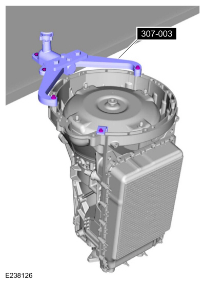
Using the special tool, install the transmission on a bench.
Use Special Service Tool: 307-003
(T57L-500-B)
Holding Fixture, Transmission.
-
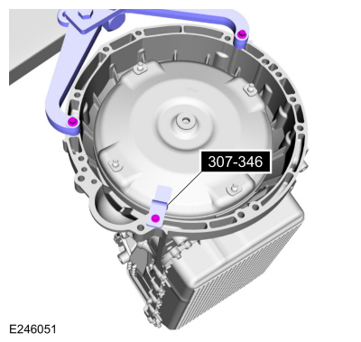
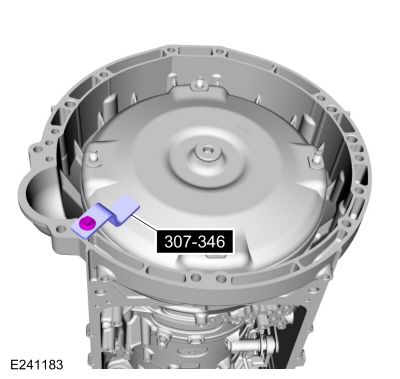
Remove the special tool.
Use Special Service Tool: 307-346
(T97T-7902-A)
Retainer, Torque Converter.
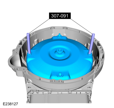
-
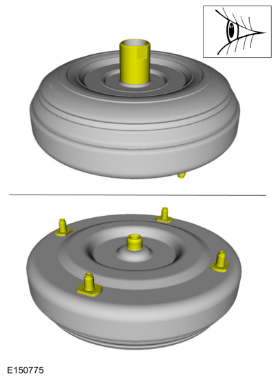
Using the special tool, remove the torque converter.
Use Special Service Tool: 307-091
Handle, Torque Converter.
-
A new or remanufactured torque converter must be installed if one or more of the following statements are true:
-
The sealing surface has a groove worn from the seal.
-
A torque converter malfunction has been determined based on complete diagnostic procedures.
-
The torque converter stud or studs, threaded pads, impeller hub or bushing are damaged.
-
The torque converter exhibits external discoloration (due to overheating).
-
There is evidence of water or antifreeze contamination.
-
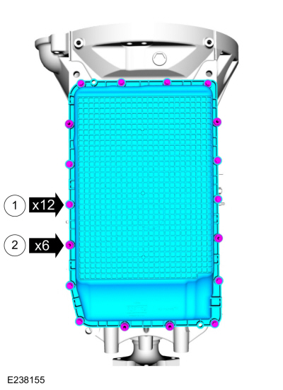
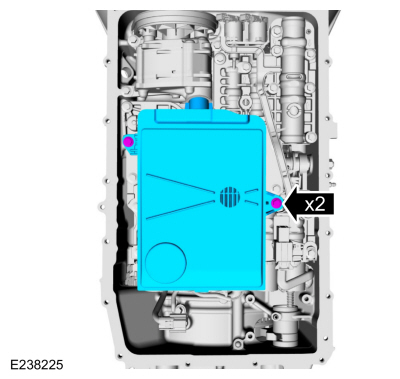
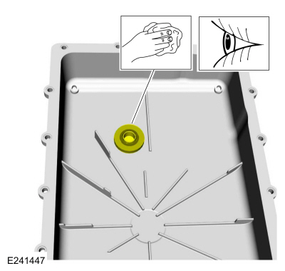
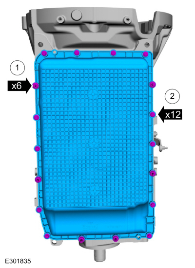
NOTE:
Note the location of the bolts and studbolts for assembly.
Remove the bolts and studbolts and the transmission fluid pan.
-
Bolts
-
Studbolts
-
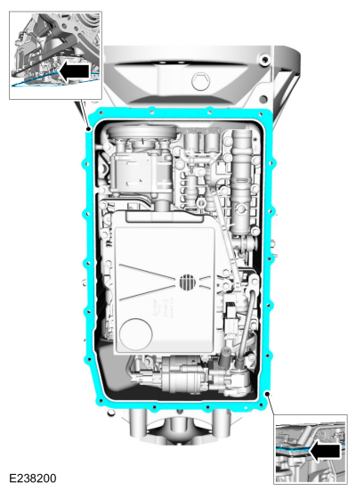
NOTE:
The transmission fluid pan gasket can be reused if not damaged.
NOTE:
Note the location of the alignment tabs.
Remove the transmission fluid pan gasket.
-
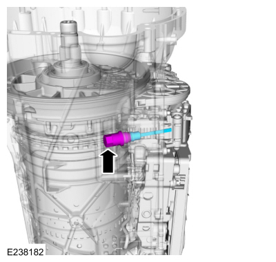
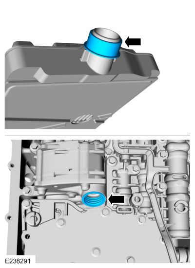
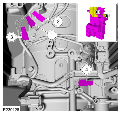
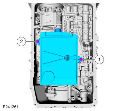
Remove the transmission fluid level indicator and plug assembly.
Auto-Start-Stop vehicles
-
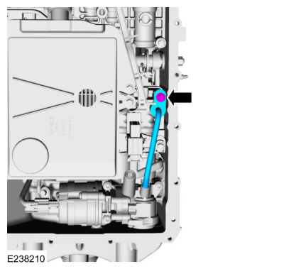
Remove the bolt and the transmission fluid auxiliary pump tube.
-
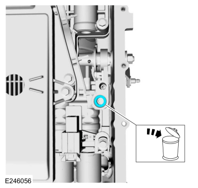
Remove and discard the transmission fluid auxiliary pump tube seal.
-
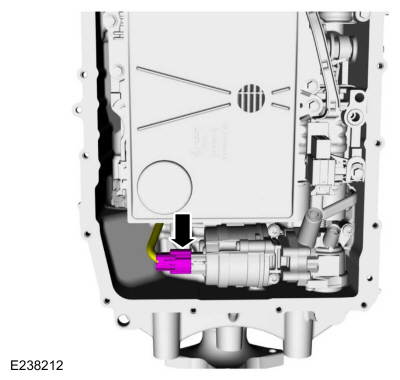
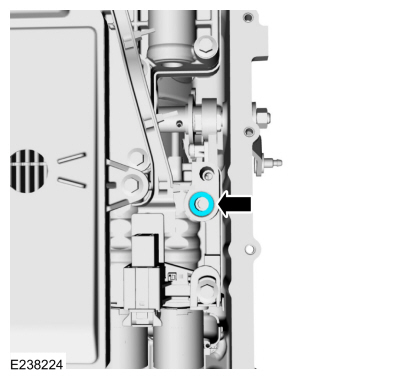
Disconnect the transmission fluid auxiliary pump electrical connector.
-
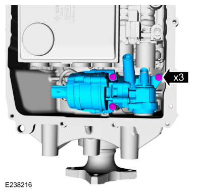
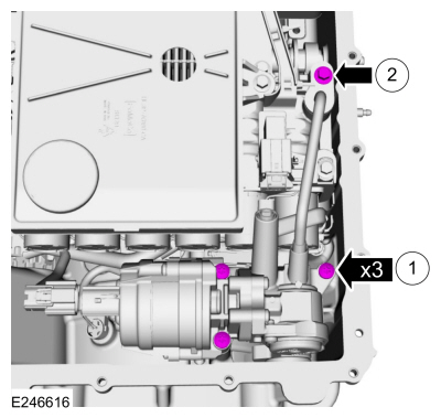
NOTE:
If the transmission fluid was contaminated from a
catastrophic failure, replace the transmission fluid auxiliary pump.
Remove the bolts and the transmission fluid auxiliary pump.
All vehicles
-
NOTE:
The transmission fluid filter may be reused if no excessive contamination is indicated.
Remove the 71 mm and 20 mm bolts and the transmission fluid filter.
-
NOTE:
The transmission fluid filter seal will either
come off with the transmission fluid filter or it will be stuck in the
pump.
Remove the transmission fluid filter seal.
-
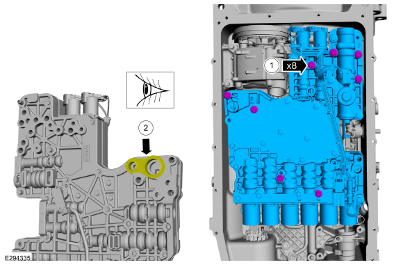
Disconnect the main control main electrical connector.
-
-
Remove the 68 mm bolts and the main control assembly.
-
Check to see if the main control-to-transmission fluid pump seal is attached to the main control.
-
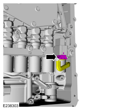
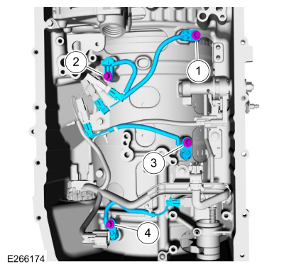
Unlock and disconnect the speed sensors.
-
Intermediate Speed Sensor A (ISSA)
-
TSS sensor
-
Intermediate Speed Sensor B (ISSB)
-
OSS sensor
-
Remove the speed sensors.
-
Intermediate Speed Sensor A (ISSA)
-
TSS sensor
-
Intermediate Speed Sensor B (ISSB)
-
OSS sensor
-
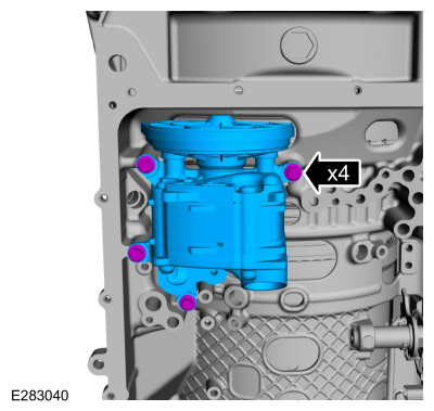
Remove the bolts and the transmission fluid pump.
-
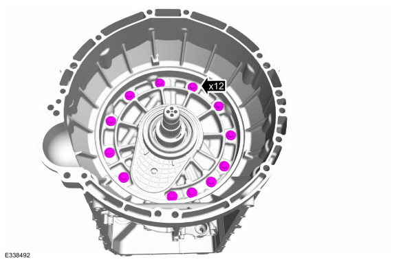
Rotate the transmission to a vertical position. Remove the front support assembly bolts.
-
-
NOTE:
Front support bolts with External Torx Plus® Low Profile (EPL) bolt heads may be reused.
Remove and discard the seals.
-
NOTE:
Front support bolts with external hex flange heads with sealant on the flange are not reusable.
Discard the bolts.
-
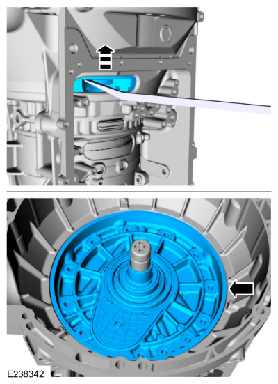
NOTICE:
Be careful not to contact the transmission fluid pump drive gear, or damage to the gear can occur.
Using a prybar, pry the front support assembly out
of the transmission case and remove the front support assembly.
-
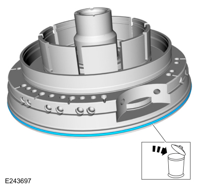
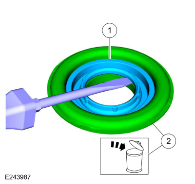
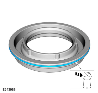
Remove and discard the front support-to-case seal.
-
-
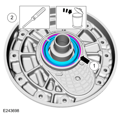
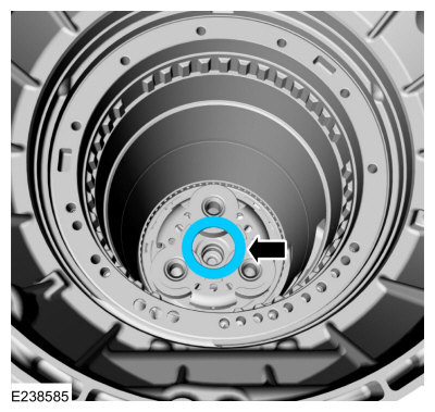
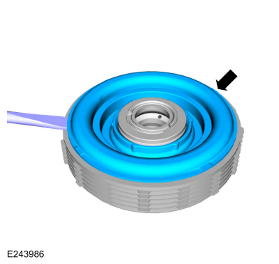
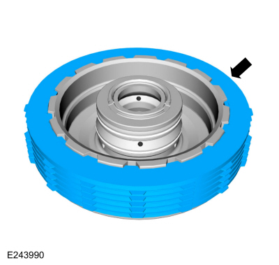
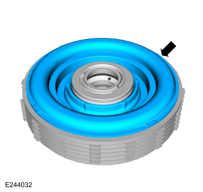
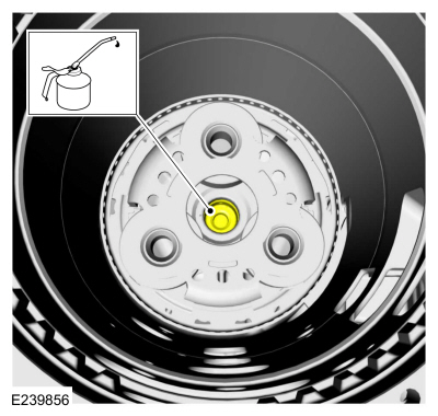
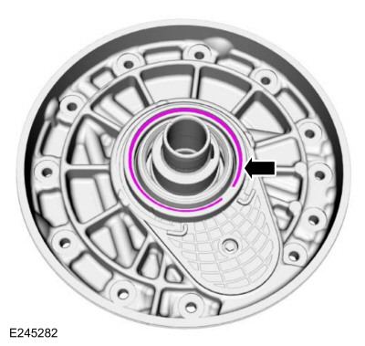
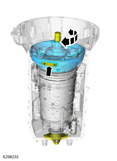
Remove the torque converter hub seal snap ring.
-
NOTE:
When removing the torque converter hub seal
use care not to scratch the front support cover sealing surface.
Remove and discard the torque converter hub seal.
-
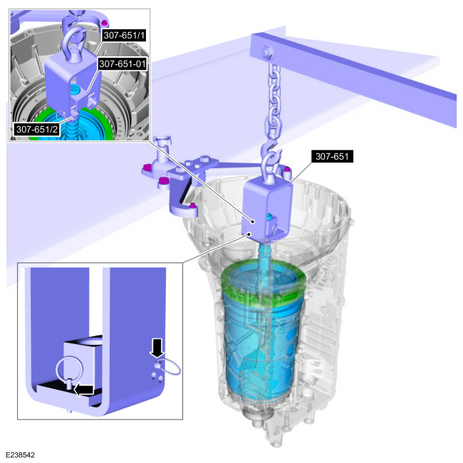
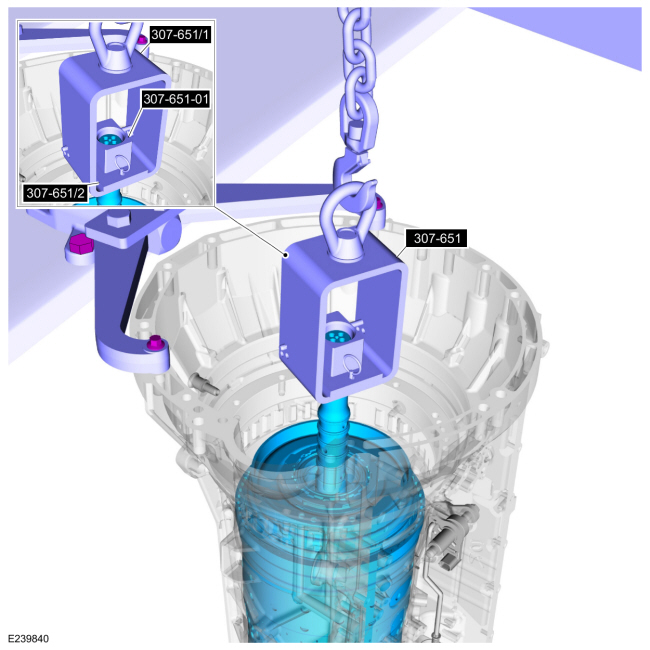
Using the special tools and a floor crane, remove the clutch and planetary assembly.
Use Special Service Tool: 307-651
Bracket, Pump Remover/Installer.
, 307-651-01
Adapter for 307-651 (Super Sub Assembly Lifting).
-
Remove the (T9) thrust bearing.
-
Remove the A clutch assembly. If the clutch plates
are not excessively worn or damaged, they can be reused.
-
Using a magnet, remove the selective shim and the (T3) thrust bearing.
Use the General Equipment: Magnet
-
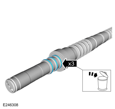
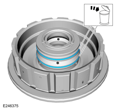
Remove and discard the input shaft front Teflon® seals.
-
Remove one side of the No. 1 planetary carrier snap ring.
-
Flip the clutch and planetary assembly over with the
input shaft through a hole in the bench. Remove the No. 1 planetary
carrier snap ring and remove the clutch and planetary container
cylinder.
-
Remove the (T8) thrust bearing.
-
Remove the E clutch and input shaft assembly.
-
NOTE:
Pry up from the 2 tabs to prevent the bearing from separating.
Remove the (T6) thrust bearing.
-
Remove the snap ring and the No. 3 ring gear.
-
Remove the rear No. 3 ring gear snap ring.
-
Remove the input shaft and the E clutch from No. 4 shell and sun gear.
-
NOTE:
Pry up from the 2 tabs to prevent the bearing from separating.
Remove the (T7) thrust bearing.
-
Remove the snap ring and remove the input shaft from the E clutch assembly.
-
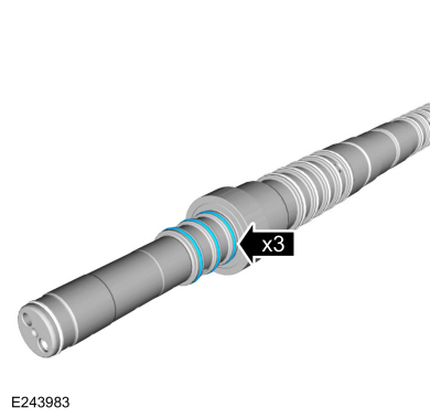
Remove and discard the input shaft-to-sun gear No. 3 shaft Teflon® seals.
-
NOTE:
The input shaft may contain D-ring or O-ring E
clutch seals, depending on the production level of the transmission.
Remove and discard the input shaft D-ring or O-ring seals.
-
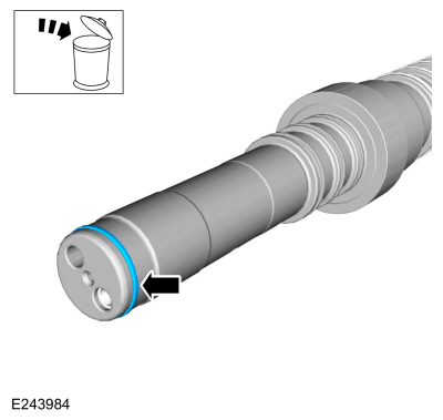
Remove and discard the input shaft Teflon® seal.
-
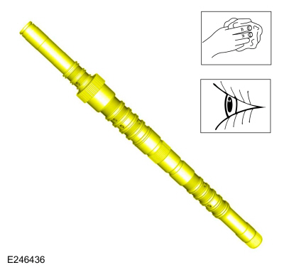
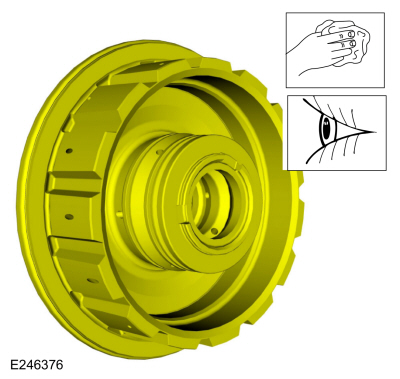
Clean and inspect the input shaft.
-
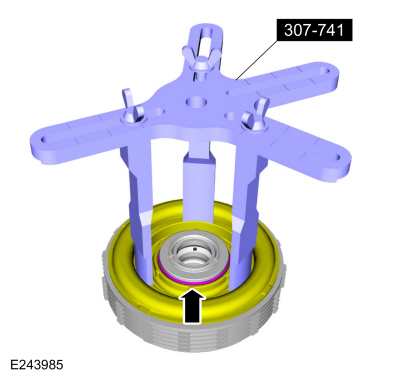
NOTICE:
Do not compress the balance dam too far or
damage to the E clutch hub can occur. Only compress the E clutch hub far
enough to remove the retainer.
Using the special tool and a press, compress the E clutch balance dam and remove the retainer.
Use Special Service Tool: 307-741
Spring Compressor, F Clutch.
Use the General Equipment: Hydraulic Press
-
Pry the E clutch piston and balance dam upward and remove the piston and balance dam from the E clutch hub.
-
Remove the E clutch balance dam and discard the E clutch piston.
-
E clutch balance dam
-
E clutch piston
-
Remove and discard the E clutch balance dam outer seal.
-
Remove the E clutch piston return spring.
-
Remove the E clutch assembly. Inspect the clutch
plates for excessive wear or damage. If the clutch plates are
excessively worn or damaged replace as necessary. If the clutch plates
are not excessively worn or damaged, they can be reused.
-
Remove and discard the E clutch piston and balance dam inner seals.
-
Clean and inspect the E clutch hub.
Installation
-
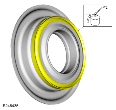
Install the new E clutch piston and balance dam inner seals. Lubricate the seals with petroleum jelly.
-
NOTE:
Clutch plate quantity is model dependant based on engine displacement.
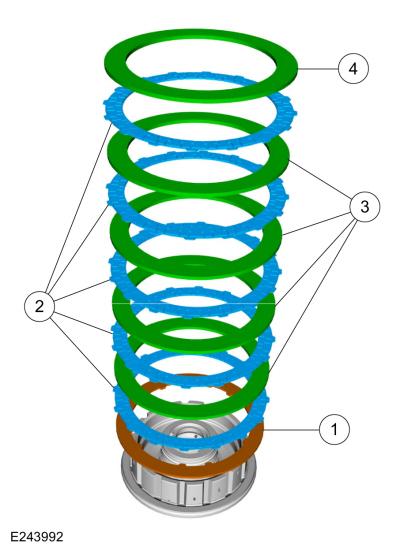
Soak the E clutch plates in clean transmission fluid. Install the E clutch assembly.
-
Pressure plate (select fit)
-
Friction plates
Material: Motorcraft® MERCON® ULV Automatic Transmission Fluid
/ XT-12-QULV
(WSS-M2C949-A, )
(MERCON® ULV)
-
NOTE:
Align the inner splines of the steel plates with the pressure plate internal splines.
Steel plates
-
Apply plate (2.9-3.0)
-
Install the E clutch piston return spring.
-
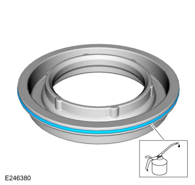
Install a new E clutch balance dam outer seal. Lubricate the seal with petroleum jelly.
-
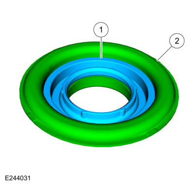
Install the E clutch balance dam in the new E clutch piston.
-
E clutch balance dam
-
E clutch piston
-
Lubricate the new E clutch piston seal with petroleum jelly.
-
Install the new E clutch piston and balance dam in the E clutch hub.
-
NOTICE:
Do not compress the balance dam too far or damage to
the E clutch hub can occur. Only compress the E clutch hub far enough
to install the retainer.
Using the special tool and a press, compress the E clutch balance dam and install the retainer.
Use Special Service Tool: 307-741
Spring Compressor, F Clutch.
Use the General Equipment: Hydraulic Press
-
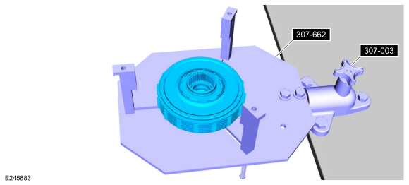
Assemble the special tools and position the E clutch assembly on the special tool.
Use Special Service Tool: 307-662
Gauge, Clutch Pack Endplay.
, 307-003
(T57L-500-B)
Holding Fixture, Transmission.
-
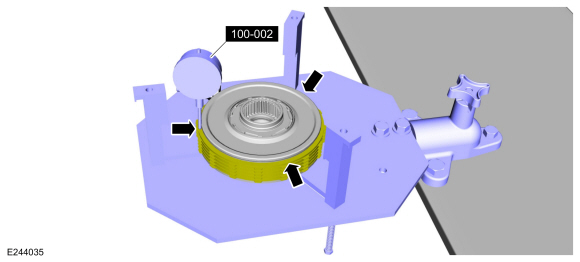
Using the special tool, measure the E clutch clearance.
Position the plunger so it rests on the top surface of the pressure
plate. Zero the dial indicator. Pull up on the pressure plate and
measure and record the clutch clearance in 3 different places. Average
the 3 recorded clutch clearance measurements and compare the measurement
to the clutch clearance chart in specifications to determine the
correct size pressure plate. Install the correct E clutch pressure
plate.
Refer to: Specifications (307-01 Automatic Transmission - 10-Speed Automatic Transmission – 10R80, Specifications).
Use Special Service Tool: 100-002
(TOOL-4201-C)
Holding Fixture with Dial Indicator Gauge.
-
NOTE:
The E clutch seals have been updated to O-ring
seals. The new seal kit may contain D-ring seals or O-ring seals, either
can be used.
Install the new input shaft E clutch seals.
-
Install the input shaft in the E clutch and install the snap ring.
-
Install the (T7) thrust bearing onto the E clutch with the tab locators up. Snap the bearing into place.
-
NOTE:
Align the outer splines on the friction plates.
Install the input shaft and the E clutch into the No. 4 shell and sun gear.
-
Install the lower rear No. 3 ring gear snap ring.
-
Install the No. 3 ring gear and the snap ring. Align the snap ring gap 180° from the bottom snap ring gap.
-
Install the (T6) thrust bearing onto the E clutch with the tab locators down. Snap the bearing into place.
-
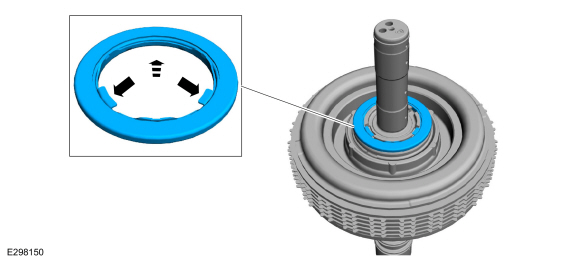
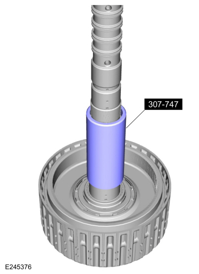
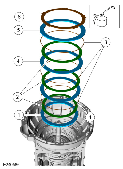
Install the special tool and adjust the special tool to
align the bottom edge of the tool with the top edge of the bottom
Teflon® seal groove.
Use Special Service Tool: 307-747
Installer/ Sizer , Input Shaft Solid Sealing Rings; Large.
-
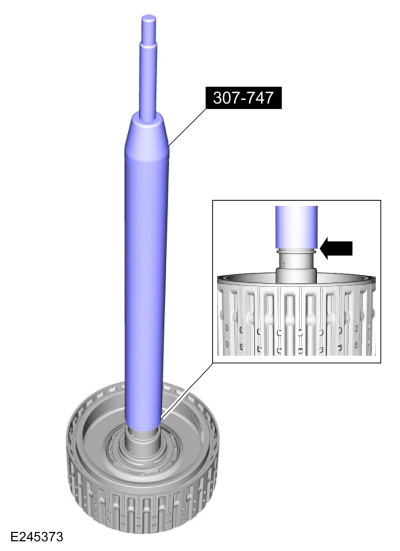
Install a new Teflon® seal on the special tool.
Use Special Service Tool: 307-747
Installer/ Sizer , Input Shaft Solid Sealing Rings; Large.
-
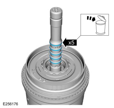
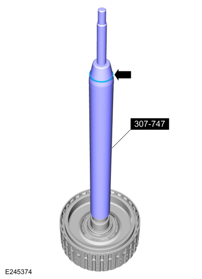
Using the top half of the special tool, slide the
Teflon® seal into the groove. Remove the special tools and repeat the
steps for the other 4 Teflon® seals.
Use Special Service Tool: 307-747
Installer/ Sizer , Input Shaft Solid Sealing Rings; Large.
-
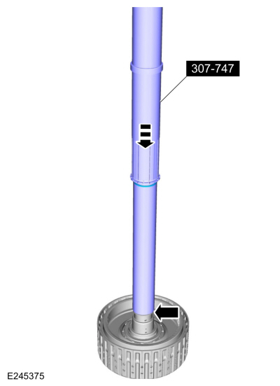
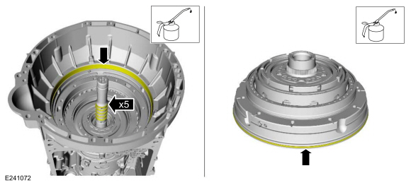
Install the special tool to size the 5 Teflon® seals.
Use Special Service Tool: 307-747
Installer/ Sizer , Input Shaft Solid Sealing Rings; Large.
-
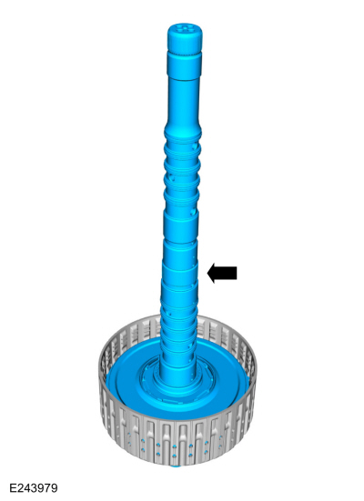
Install the E clutch and input shaft assembly.
-
Install the (T8) thrust bearing.
-
-
NOTE:
Some early build transmissions are not equipped with lazer applied ink marks.
Inspect the No. 1 planetary carrier and the clutch
and planetary container cylinder for lazer applied ink marks.
-
NOTICE:
If ink marks are present the marks must be aligned or a transmission vibration can occur.
If ink marks are present align the marks and install
the clutch and planetary container cylinder onto the No. 1 planetary
carrier and install the snap ring. Make sure the snap ring is seated.
-
Install the No. 1 planetary carrier snap ring. Make sure the snap ring is seated.
-
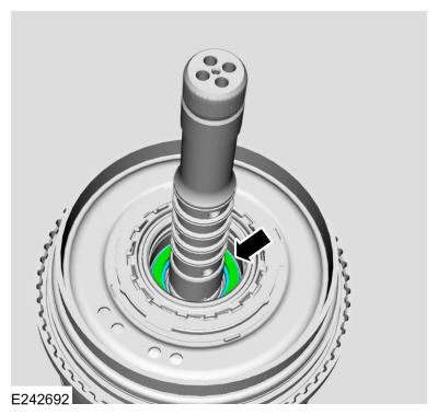
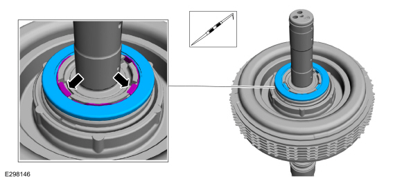
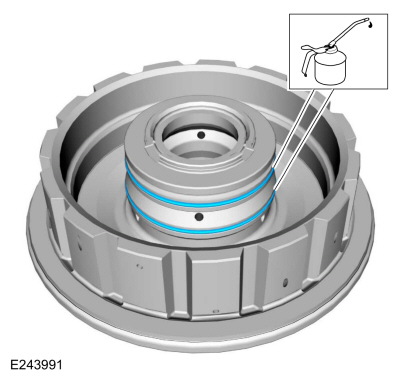
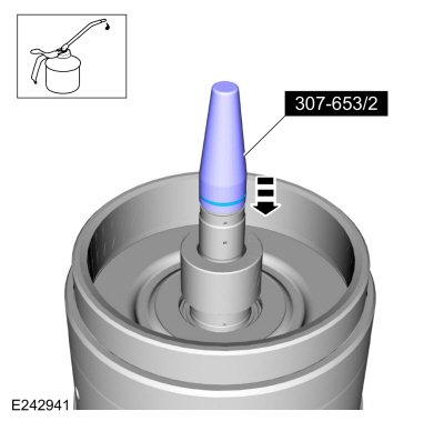
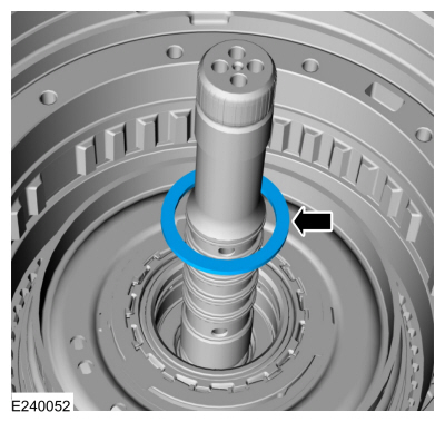
Using the special tool, install a new Teflon® seal in the groove on the input shaft.
Use Special Service Tool: 307-653
Sizer, Input Shaft Teflon Seal.
-
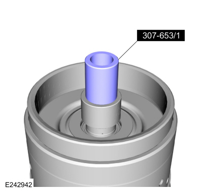
Using the special tool, size the Teflon® seal.
Use Special Service Tool: 307-653
Sizer, Input Shaft Teflon Seal.
-
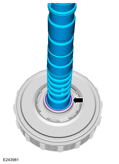
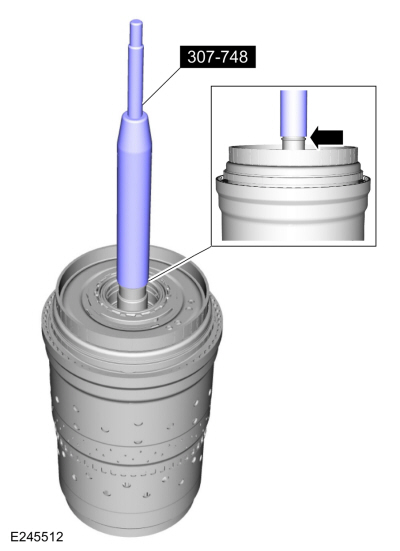
Install the special tool and adjust the special tool to
align the bottom edge of the tool with the top edge of the bottom
Teflon® seal groove.
Use Special Service Tool: 307-748
Installer/Sizer, Input Shaft Solid Sealing Rings; Small.
-
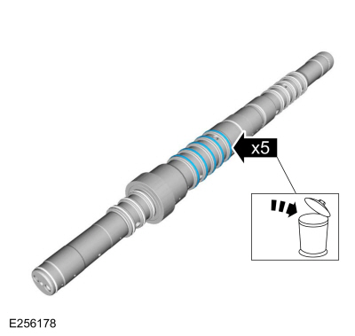
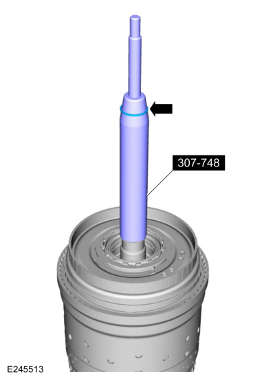
Install a new Teflon® seal on the special tool.
Use Special Service Tool: 307-748
Installer/Sizer, Input Shaft Solid Sealing Rings; Small.
-
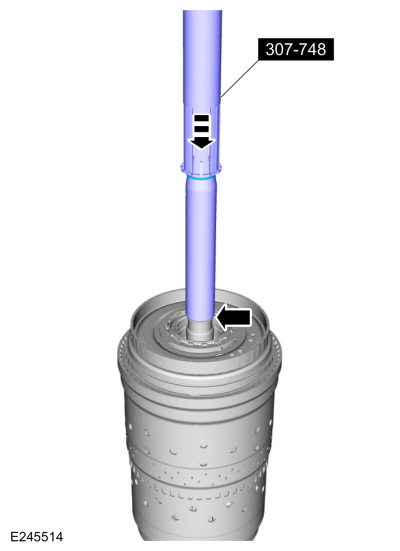
Using the top half of the special tool, slide the
Teflon® seal into the groove. Remove the special tools and repeat the
steps for the other 4 Teflon® seals.
Use Special Service Tool: 307-748
Installer/Sizer, Input Shaft Solid Sealing Rings; Small.
-
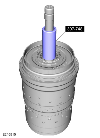
Install the special tool to size the 5 Teflon® seals.
Use Special Service Tool: 307-748
Installer/Sizer, Input Shaft Solid Sealing Rings; Small.
-
Install the (T9) thrust bearing.
-
Lubricate the output shaft bushing with petroleum jelly.
-
Using the special tools and a floor crane, install the clutch and planetary assembly.
Use Special Service Tool: 307-651
Bracket, Pump Remover/Installer.
, 307-651-01
Adapter for 307-651 (Super Sub Assembly Lifting).
-
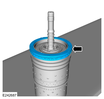
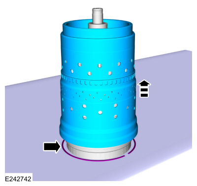
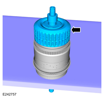
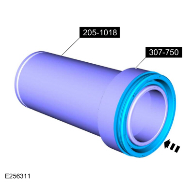
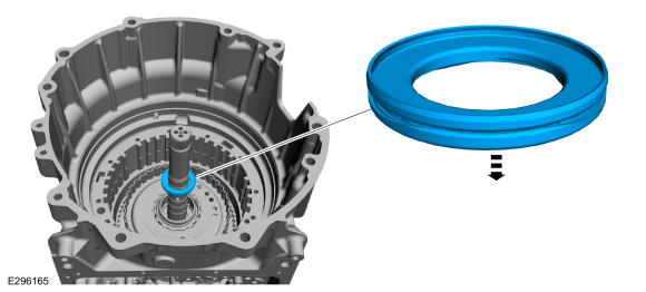
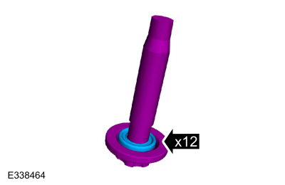
Install the new torque converter hub seal on the special tools.
Use Special Service Tool: 307-750
Installer, Converter Seal.
, 205-1018
Installation Tube.
-
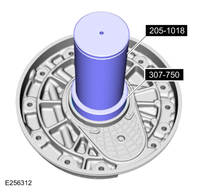
Using the special tools, install the new torque converter hub seal.
Use Special Service Tool: 307-750
Installer, Converter Seal.
, 205-1018
Installation Tube.
-
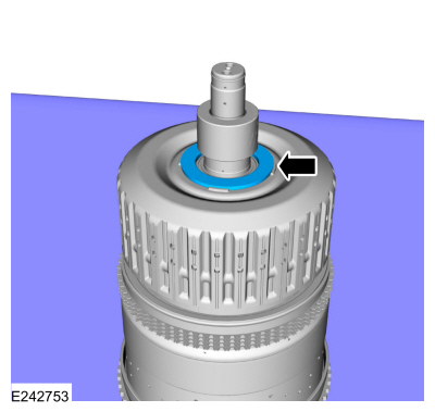
Install the torque converter hub seal snap ring.
-
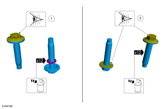
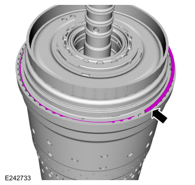
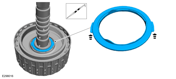
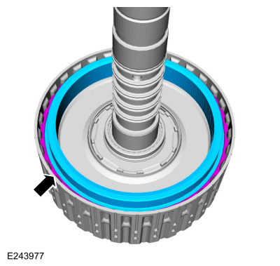
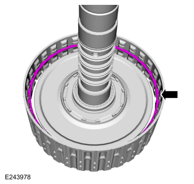
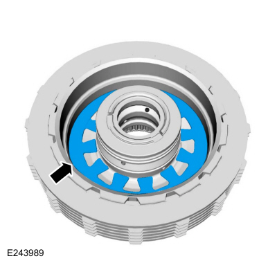
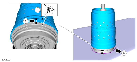
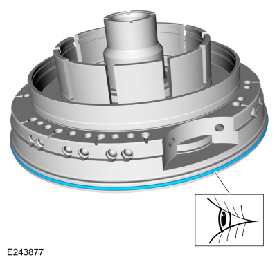
Install the new front support-to-case seal with the seal color visible from the outside.
-
Install the (T3) thrust bearing.
-
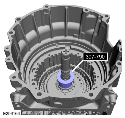
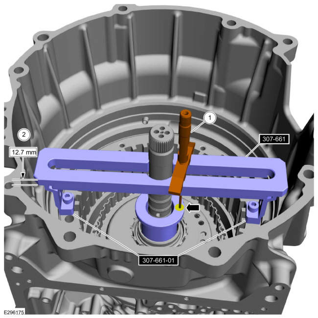
Install the special tool.
Use Special Service Tool: 307-790
Endplay Check Gauge.
-
NOTE:
The special tool height 0.50 in (12.7 mm) must be
subtracted from the measurement to get the correct measurement A height.
Using the special tools and a depth gauge, measure the
distance from the top of the special tool to the top of the (T3) thrust
bearing special tool in 2 different places. Average the measurements and
subtract 0.50 in (12.7 mm). Record this as measurement A.
-
Measure it
-
Subtract it
Use Special Service Tool: 307-661
Gauge, End Play.
, 307-661-01
Spacers/Plate, Clearance Gage.
-
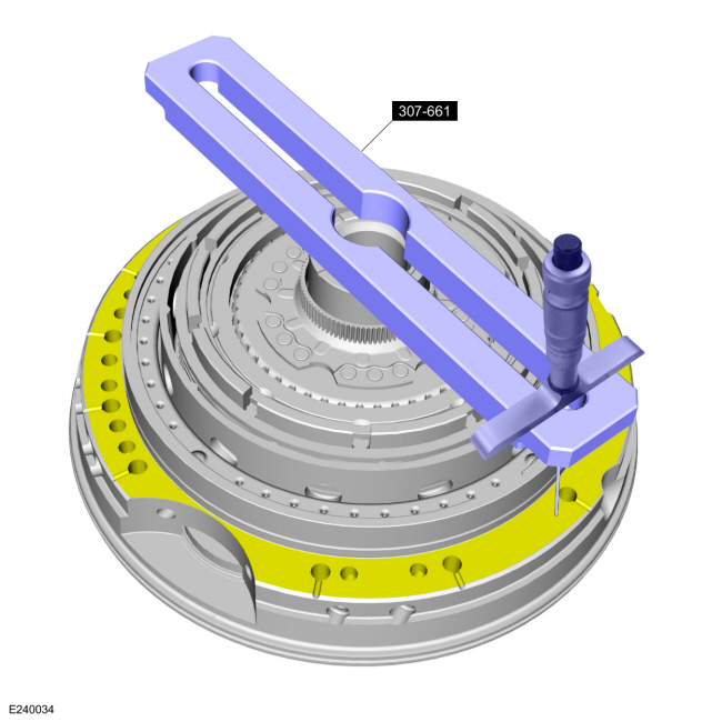
Using the special tool and a depth gauge, measure the
distance from the top of the special tool to the transmission deck
mating surface in 2 different places. Average the measurements. Record
this measurement as measurement B.
Use Special Service Tool: 307-661
Gauge, End Play.
-
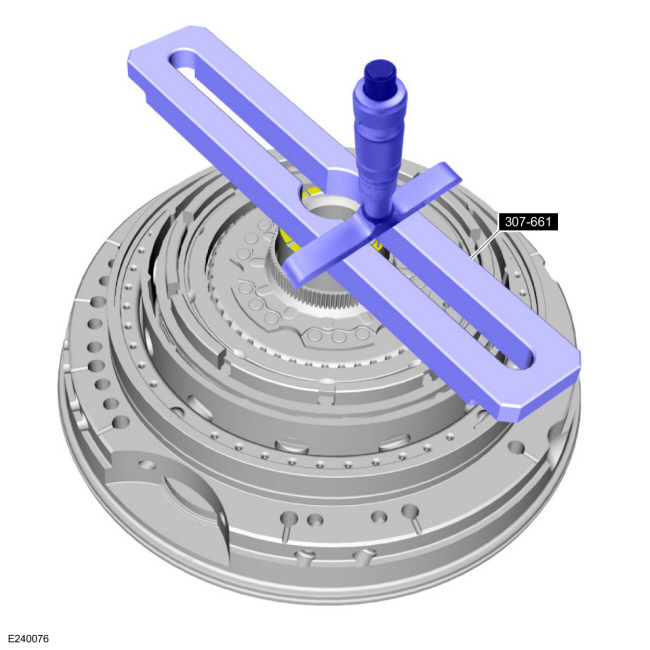
Using the special tool and a depth gauge, measure the
distance from the top of the special tool to (T3) thrust bearing surface
in 2 different places. Average the measurements. Record this as
measurement C.
Use Special Service Tool: 307-661
Gauge, End Play.
-
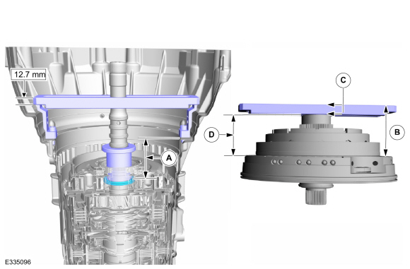
NOTE:
Recorded measurement A compensates for the differences in height of the special tool.
Calculate the correct shim thickness. Subtract
measurement C from measurement B and record this as measurement D.
Subtract measurement D from measurement A to get the clearance between
the front support and the (T3) thrust bearing. Using the Selective Fit
Shim Charts in specifications, select the correct shim to bring the
transmission end clearance into specification.
Refer to: Specifications (307-01 Automatic Transmission - 10-Speed Automatic Transmission – 10R80, Specifications).
-
Install the selective shim.
-
NOTICE:
If replacing A clutch separating springs, all
separating springs must be replaced as a matching set or damage can
occur.
NOTE:
Clutch plate quantity is model dependant based on engine displacement.
Soak the A clutch plates in clean transmission fluid. Install the A clutch assembly.
-
Pressure plate
-
Friction plates
Material: Motorcraft® MERCON® ULV Automatic Transmission Fluid
/ XT-12-QULV
(WSS-M2C949-A, )
(MERCON® ULV)
-
Separator springs
-
Steel plates
-
Apply plate (select fit)
-
Wave spring
-
Lubricate the transmission case-to-front support sealing
surface, the Teflon seals and the front support O-ring with petroleum
jelly.
-
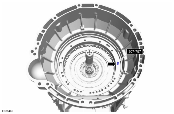
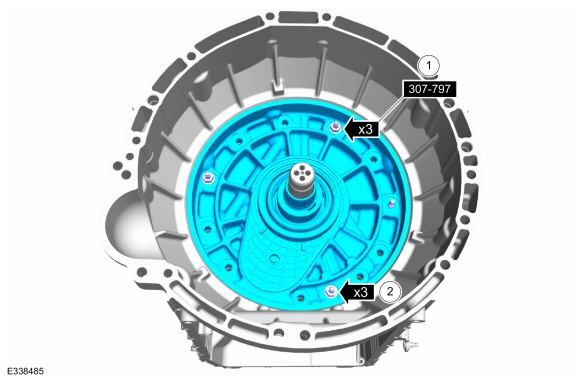
Install the special tool in the location shown.
Use Special Service Tool: 307-797
Installer, Alignment Studs (3) & Alignment Pin (All 10R).
-
Install the front support into the transmission case.
Align the pump gear to the pump drive gear pocket area. Rotate the input
shaft to align the one-way clutch splines with the No. 1 sun gear.
-
-
Install the special tool studs, washers and nuts in the location shown.
Use Special Service Tool: 307-797
Installer, Alignment Studs (3) & Alignment Pin (All 10R).
-
Tighten the special tool nuts evenly to seat the front support assembly to the transmission case.
-
NOTE:
New bolts are produced with the washers installed.
If the bolts are being reused the new washers must be installed.
If necessary, install the new front support assembly bolt washers.
-
-
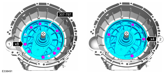
With the special tools installed, hand tight the front support bolts in a crisscross pattern.
-
Remove the special tools and install the front support bolts hand tight in a crisscross pattern..
-
Tighten the front support bolts in a crisscross pattern.
Torque:
26 lb.ft (35 Nm)
-
Using the special tool, install the torque converter.
Use Special Service Tool: 307-091
Handle, Torque Converter.
-
Install the special tool to hold the torque converter.
Use Special Service Tool: 307-346
(T97T-7902-A)
Retainer, Torque Converter.
-
Install the speed sensors.
-
Intermediate Speed Sensor A (ISSA)
-
TSS sensor
-
Intermediate Speed Sensor B (ISSB)
-
OSS sensor
-
Connect and lock the speed sensors.
-
Intermediate Speed Sensor A (ISSA)
-
TSS sensor
-
Intermediate Speed Sensor B (ISSB)
-
OSS sensor
-
Install the transmission fluid pump and the bolts.
Torque:
71 lb.in (8 Nm)
-
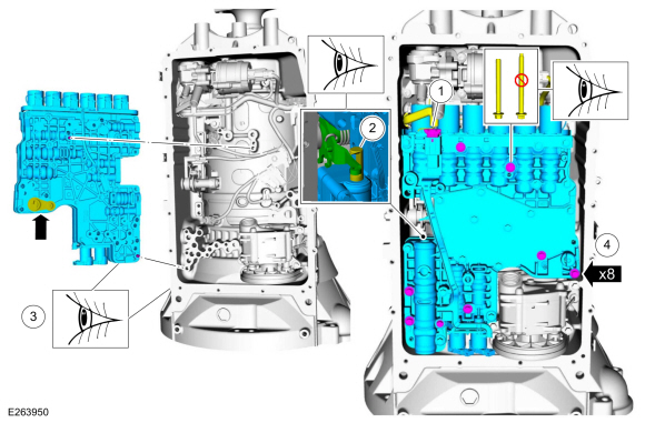
NOTICE:
Do not install a 71 mm length bolt in the location
shown or the transmission clutch and planetary container will be damaged
and result in transmission failure.
Loosely install the main control valve body.
-
NOTE:
Be sure the main control-to-case seal is attached to the main control.
Connect the internal wiring harness electrical connector while installing the main control valve body.
-
If equipped with a park pawl lock valve, align the TR sensor with the park pawl lock valve.
-
Align the guide pins on the main control valve body with the alignment holes in the transmission case.
-
Loosely install the 68 mm length main control-to-transmission case bolts.
-
Tighten the bolts in the sequence shown.
Torque:
89 lb.in (10 Nm)
-
Lock the main control main electrical connector.
-
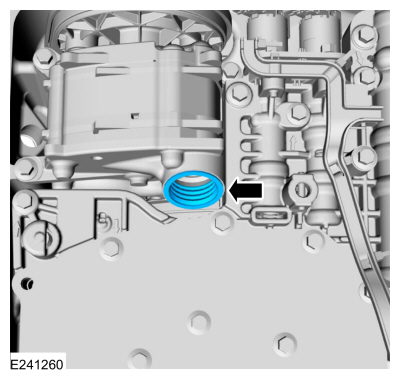
Install the filter seal in the pump.
-
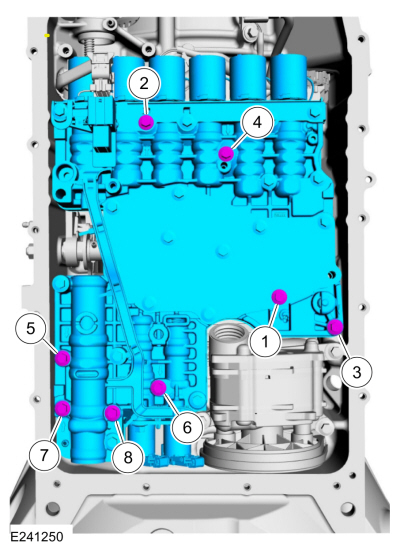
NOTICE:
If the bolts are installed in the wrong locations, transmission damage will occur.
NOTE:
The transmission fluid filter may be reused if no excessive contamination is indicated.
Install the filter and the bolts in the correct locations.
-
Short bolt 20 mm
-
Long bolt 71 mm
-
Torque:
93 lb.in (10.5 Nm)
Auto-Start-Stop vehicles
-
Install the transmission fluid auxiliary pump and loosely install the bolts.
-
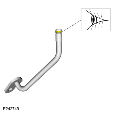
Install the new transmission fluid auxiliary pump tube seal.
-
Inspect the transmission fluid auxiliary pump tube O-ring.
-
Install the transmission fluid auxiliary pump tube and loosely install the bolt.
-
-
Transmission fluid auxiliary pump bolts
Torque:
97 lb.in (11 Nm)
-
Transmission fluid auxiliary pump tube bolt
Torque:
106 lb.in (12 Nm)
-
Connect the transmission fluid auxiliary pump electrical connector.
All vehicles
-
Clean and inspect the magnet and the retainer.
-
NOTE:
The transmission fluid pan gasket can be reused if not damaged.
Align the tabs in the noted location and install the transmission fluid pan gasket.
-
NOTE:
Install the bolts and studbolts in the correct locations noted during removal.
Install the transmission fluid pan and loosely install the bolts and studbolts.
-
Tighten the studbolts in a crisscross pattern.
Torque:
106 lb.in (12 Nm)
-
Tighten the bolts in a crisscross pattern.
Torque:
89 lb.in (10 Nm)
-
Loosely install the transmission fluid level indicator.
-
Install the transmission assembly.
Refer to: Transmission (307-01 Automatic Transmission - 10-Speed Automatic Transmission – 10R80, Removal and Installation).
Removal
NOTE:
The Solenoid Body Strategy Data Download procedure must be performed if a new main control valve body is installed.
NOTE:
If a main control valve body overhaul is carried out or a new SS is
installed, carry out the adaptive learning drive cycle procedure at the
end of the repair...
Other information:
Inspection
Recover the refrigerant.
Refer to: Air Conditioning (A/C) System Recovery, Evacuation and
Charging (412-00 Climate Control System - General Information, General
Procedures).
Disconnect the condenser from the A/C system...
Special Tool(s) /
General Equipment
Flat-Bladed Screwdriver
Interior Trim Remover
Materials
Name
Specification
3M™ Super-Fast Repair Adhesive04747
-
Removal
Remove the following items:
On both sides...


 Main Control Valve Body. Removal and Installation