Lincoln Navigator: Interior Trim and Ornamentation / Headliner. Removal and Installation
Special Tool(s) / General Equipment
| Flat-Bladed Screwdriver | |
| Interior Trim Remover |
Materials
| Name | Specification |
|---|---|
| 3M™ Super-Fast Repair Adhesive 04747 |
- |
Removal
-
Remove the following items:
-
On both sides.
Remove the A-pillar trim panel.
Refer to: A-Pillar Trim Panel (501-05 Interior Trim and Ornamentation, Removal and Installation).
-
On both sides.
Remove the B-pillar trim panel.
Refer to: B-Pillar Trim Panel (501-05 Interior Trim and Ornamentation, Removal and Installation).
-
On both sides.
Remove the C-pillar trim panel.
Refer to: C-Pillar Trim Panel (501-05 Interior Trim and Ornamentation, Removal and Installation).
-
On both sides.
Remove the D-pillar trim panel.
Refer to: D-Pillar Trim Panel - Short Wheelbase (501-05 Interior Trim and Ornamentation, Removal and Installation).
Refer to: D-Pillar Trim Panel - Long Wheelbase (501-05 Interior Trim and Ornamentation, Removal and Installation).
-
On RH side.
Remove the front seat.
Refer to: Front Seat (501-10A Front Seats, Removal and Installation).
-
Remove the glove compartment.
Refer to: Glove Compartment (501-12 Instrument Panel and Console, Removal and Installation).
-
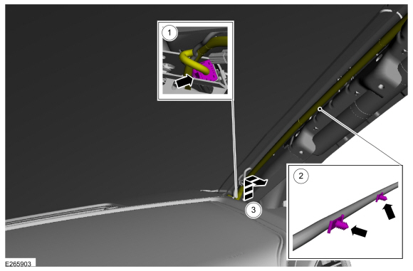
On both sides.
-
Position the headliner wiring harness aside.
-
Disconnect the headliner wiring harness.
-
Release the headliner wiring harness clips.
-
Disconnect the headliner wiring harness.
 |
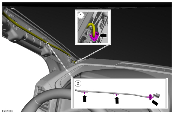
-
On LH side.
Position the headliner wiring harness aside.
-
Disconnect headliner wiring harness electrical connector.
-
Release the headliner wiring harness retainers.
-
Disconnect headliner wiring harness electrical connector.
 |
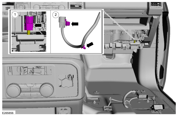
-
On RH side.
Position the headliner wiring harness aside.
-
Disconnect the headliner wiring harness electrical connector.
-
Release the headliner wiring harness retainers.
-
Feed the headliner wiring harness up past the instrument panel.
-
Disconnect the headliner wiring harness electrical connector.
 |
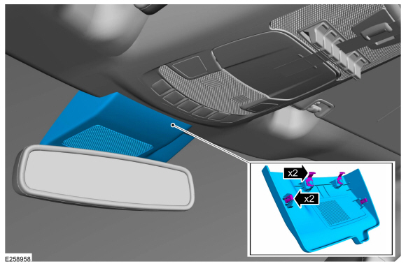
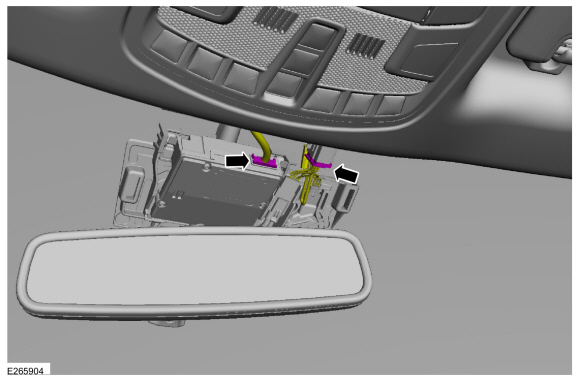
Vehicles with image processing module
-
Release the clips and remove the IPMA cover.
 |
-
Disconnect the IPMA and the rain sensor wiring harness electrical connectors.
 |
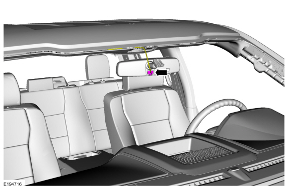
All vehicles
-
If equipped.
Disconnect the rear view mirror electrical connector.
 |
-
If equipped.
Release the clips and remove the rain sensor outer covers.
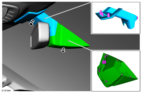 |
-
If equipped.
Disconnect the rain sensor electrical connectors.
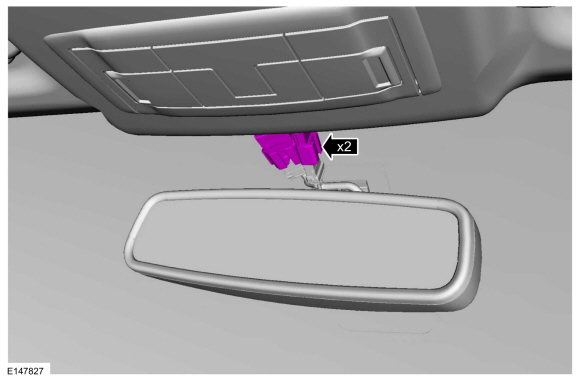 |
-
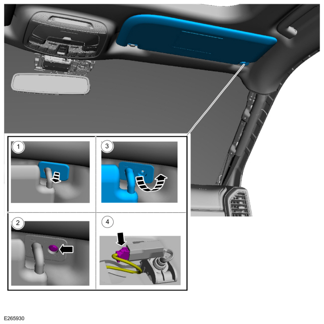
NOTE: RH shown, LH similar.
On both sides.
Remove the sun visor.
-
Remove the bolt cover.
-
Remove the bolt.
-
Remove the sun visor.
-
Disconnect the sun visor electrical connector.
-
Remove the bolt cover.
 |
-
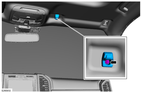
NOTE: RH shown, LH similar.
On both sides.
Remove the bolt and the sun visor clip.
 |
-
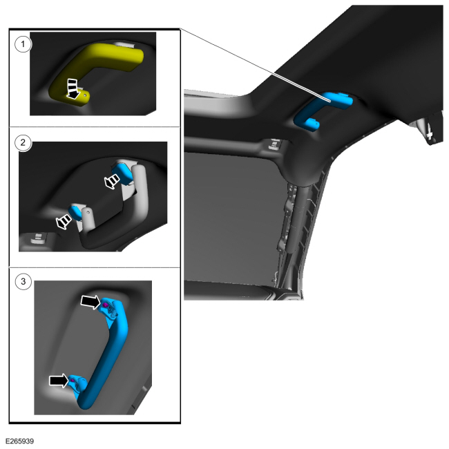
On RH side.
Remove the front passenger assist handle.
-
Position the front passenger assist handle down.
-
Remove the bolt covers.
-
Remove the bolts.
-
Position the front passenger assist handle down.
 |
-
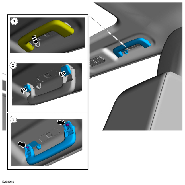
NOTE: RH shown, LH similar.
On both sides.
Remove the rear passenger assist handle.
-
Position the rear passenger assist handle down.
-
Remove the bolt covers.
-
Remove the bolts.
-
Position the rear passenger assist handle down.
 |
-
NOTE: RH shown, LH similar.
On both sides.
Remove the rear coat hook.
-
Position the rear coat hook down.
-
Remove the bolt.
-
Position the rear coat hook down.
 |
Long wheel base
-
NOTE: LH shown, RH similar.
On both sides.
Remove the third row outer seatbelt retractor D-ring bolt cover.
 |
-
NOTE: LH shown, RH similar.
On both sides.
Remove the third row outer seatbelt retractor D-ring bolt.
Torque: 30 lb.ft (40 Nm)
 |
-
NOTE: LH shown, RH similar.
On both sides.
Remove the pin-type retainer and the third row outer seatbelt retractor bracket cover.
Use the General Equipment: Interior Trim Remover
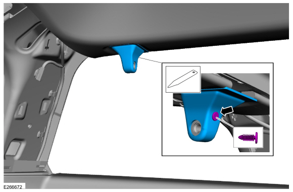 |
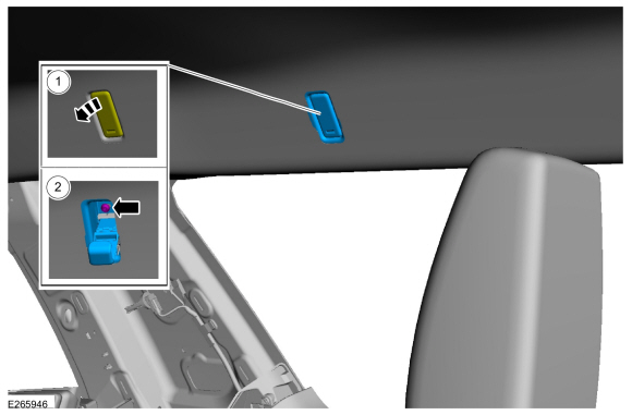
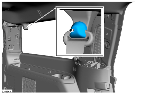
-
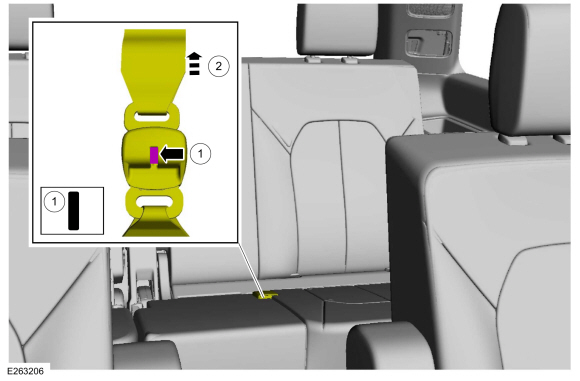
Disconnect the third row center seatbelt retractor from the third row center seatbelt retractor mini-buckle.
-
Press the release button.
Use the General Equipment: Flat-Bladed Screwdriver
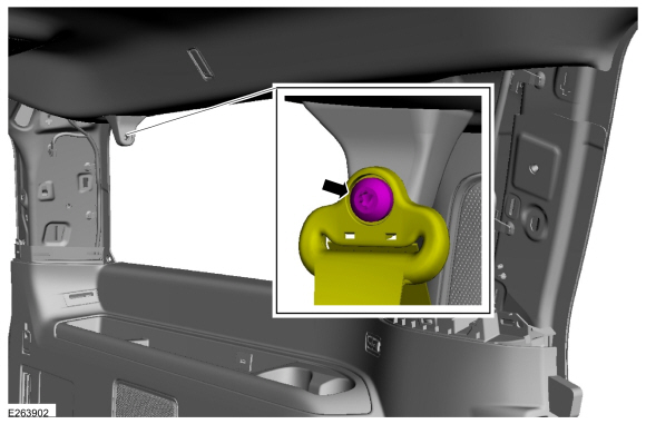
-
Release the third row center seatbelt retractor.
-
Press the release button.
 |
-
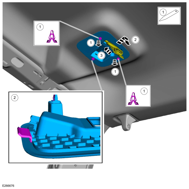
Remove the third row center seatbelt retractor cover.
-
Release the clips.
Use the General Equipment: Interior Trim Remover
-
Slide cover forward and down to release the rear tab.
-
Feed the third row center seatbelt through.
-
Release the clips.
 |
All vehicles
-
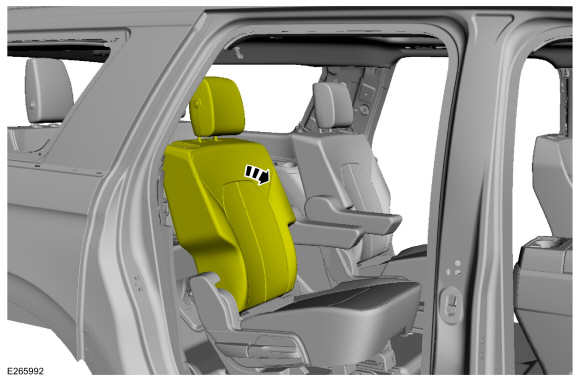
On both sides.
Position the second row seat backrest in the full flat position.
 |
-
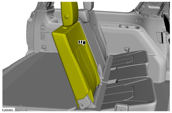
On both sides.
Position the third row seat backrest in the full flat position.
 |
-
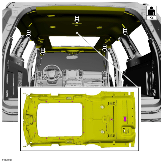
NOTE: Long wheel base with roof opening panel shown, all others similar.
Release the magnets and lower the headliner.
 |
-
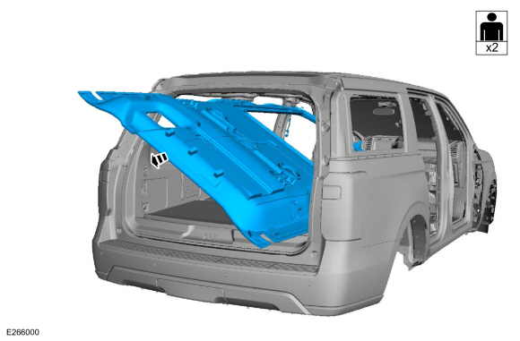
Remove the headliner.
 |
Installation
-
NOTE: These steps are only necessary when installing a new component.
NOTE: When transferring the headliner harness to a new headliner note the location of each electrical connector during removal and maintain those locations when transferring the harness. If equipped with noise cancellation the microphone connectors are the same but are not interchangeable and must maintain their original locations for the system to operate correctly.
NOTE: Obtain the specified adhesive commercially. Depending on the headliner and optional wiring harness(es), the purchase of multiple tubes is suggested.
-
Using tape, mark the wire at the exit points for proper length from headliner-to-body / roof connectors.
-
Carefully remove the wiring harness from the original headliner.
-
Using a marking tool, mark the new headliner with
the routing and exit points of the wiring harness from the original
headliner.
-
NOTICE: Make sure not to damage the wiring harness when cutting the excess adhesive from the wiring harness.
Cut and remove any excess adhesive from the wiring harness.
-
Position the wiring harness onto the new headliner,
making sure the harness has enough length to be connected to the body /
roof connectors at the tape location(s) applied earlier. Apply tape to
temporarily hold the wiring harness in position on the headliner.
-
Apply the adhesive in the same location as the
factory installed adhesive along the full length of the wiring
harness-to-headliner to avoid any NVH concern(s).
Material: 3M™ Super-Fast Repair Adhesive / 04747
-
Using tape, mark the wire at the exit points for proper length from headliner-to-body / roof connectors.
-
NOTE: Transfer parts as necessary.
NOTE: During installation, make sure the seatbelt webbing is not twisted and the seatbelts and buckles are accessible to the occupants.
To install, reverse the removal procedure.
-
Check the active restraint system for correct operation.
Refer to: Seatbelt Systems (501-20A Seatbelt Systems, Diagnosis and Testing).
 Front Door Trim Panel. Removal and Installation
Special Tool(s) /
General Equipment
Pick Hook
Interior Trim Remover
Removal
Release the clip and remove the sail panel trim panel...
 Headliner - Lowering. Removal and Installation
Special Tool(s) /
General Equipment
Flat-Bladed Screwdriver
Interior Trim Remover
Remove the following items:
On both sides...
Other information:
Lincoln Navigator 2018-2026 Workshop Manual: Welding Precautions. General Procedures
Check WARNING: Invisible ultraviolet and infrared rays emitted in welding can injure unprotected eyes and skin. Always use protection such as a welder's helmet with dark-colored filter lenses of the correct density. Electric welding will produce intense radiation, therefore, filter plate lenses of the deepest shade providing adequate visibility are recommended...
Lincoln Navigator 2018-2026 Workshop Manual: Tire Pressure Monitoring System (TPMS) Sensor Activation. General Procedures
Special Tool(s) / General Equipment 204-D081A (204-D081) Tire Pressure Monitor (TPMS) Activation NOTE: The tire pressure sensors will go into a "sleep mode" when a vehicle is stationary to conserve battery power...
Categories
- Manuals Home
- 4th Gen Lincoln Navigator Service Manual (2018 - 2026)
- Head Up Display (HUD) Module Calibration. General Procedures
- Front Seat. Removal and Installation
- Transmission Fluid Level Check. General Procedures
- All Terrain Control Module (ATCM). Removal and Installation
- Body Control Module (BCM). Removal and Installation
Rear Camber Adjustment. General Procedures
Special Tool(s) / General Equipment
Wheel Alignment SystemActivation
NOTICE: Suspension fasteners are critical parts that affect the performance of vital components and systems. Failure of these fasteners may result in major service expense. Use the same or equivalent parts if replacement is necessary. Do not use a replacement part of lesser quality or substitute design. Tighten fasteners as specified.
Using alignment equipment and the manufacturer's instructions, measure the rear camber.Use the General Equipment: Wheel Alignment System