Lincoln Navigator: Automatic Transmission - 10-Speed Automatic Transmission – 10R80 / Transmission. Removal and Installation
Special Tool(s) / General Equipment
 |
307-346
(T97T-7902-A)
Retainer, Torque Converter TKIT-1998-LM (NavigatoR) TKIT-1997-F/FLM/LT |
| Transmission Jack | |
Materials
| Name | Specification |
|---|---|
| Motorcraft® Multi-Purpose Grease Spray XL-5-A |
ESB-M1C93-B |
| Motorcraft® MERCON® ULV Automatic Transmission Fluid XT-12-QULV |
WSS-M2C949-A, MERCON® ULV |
Removal
-
With the vehicle in NEUTRAL, position it on a hoist.
Refer to: Jacking and Lifting (100-02 Jacking and Lifting, Description and Operation).
-
Remove the following items:
-
Remove the starter motor assembly.
Refer to: Starter Motor (303-06 Starting System - 3.5L EcoBoost (272kW/370PS), Removal and Installation).
-
Remove the transmission fluid heat exchanger.
Refer to: Transmission Fluid Heat Exchanger (307-02 Transmission Cooling, Removal and Installation).
-
Remove the rear driveshaft assembly.
Refer to: Rear Driveshaft (205-01 Driveshaft, Removal and Installation).
-
Remove the starter motor assembly.
-
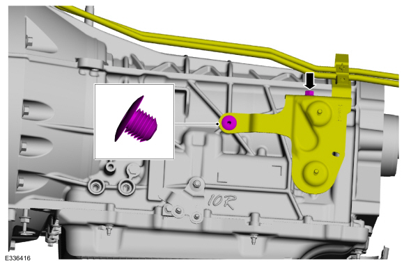
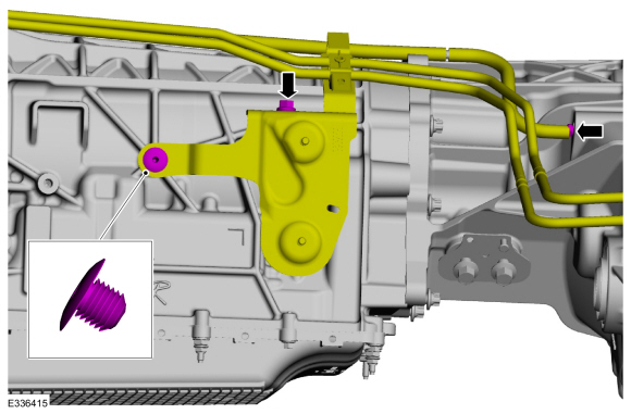
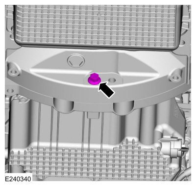
Remove the park override lever bolt.
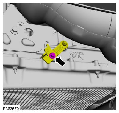 |
-
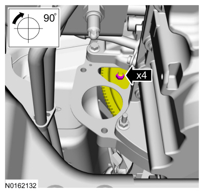
Move the park override lever to the park override position.
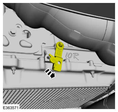 |
-
Loosely install the park override lever bolt.
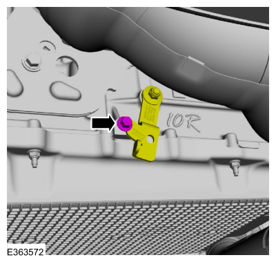 |
Four-Wheel Drive (4WD) vehicles
-
Remove the front driveshaft assembly.
Refer to: Front Driveshaft (205-01 Driveshaft, Removal and Installation).
Rear Wheel Drive (RWD) vehicles
-
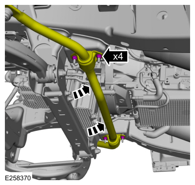
Remove and discard the stabilizer bar bracket nuts and allow the stabilizer bar to swing downward.
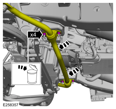 |
All vehicles
-
Remove the nut and release the retainer, position aside the transmission fluid cooler tubes.
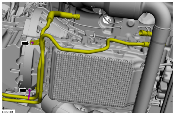 |
-
Remove the retainers and heatshield.
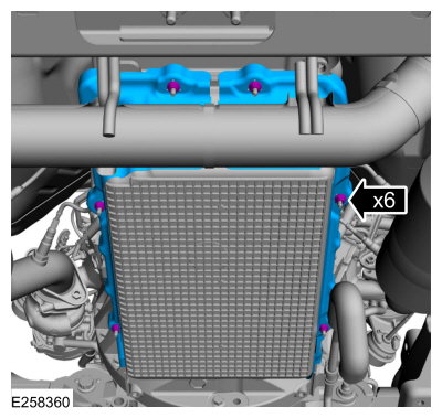 |
-
NOTE: If transmission disassembly or installation of a new transmission is necessary, drain the transmission fluid.
NOTE: Note the location of the bolts and studbolts for assembly.
Remove the bolts and the transmission fluid pan.
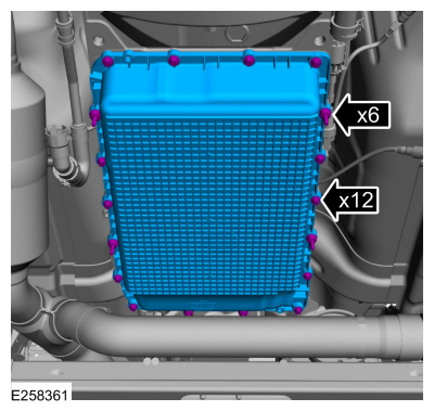 |
-
NOTE: It is not necessary to torque transmission fluid pan bolts at this time.
Install the transmission fluid pan and the bolts.
|
-
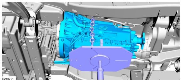
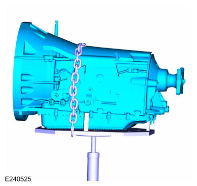
NOTICE: Secure the transmission to the transmission jack with a safety strap.
NOTE: Make sure the transmission jack makes contact on the outer ribs of the transmission fluid pan.
Using a high-lift transmission jack, support the transmission.
Use the General Equipment: Transmission Jack
 |
-
Remove the LH catalytic converter.
Refer to: Catalytic Converter LH (309-00 Exhaust System - 3.5L EcoBoost (272kW/370PS), Removal and Installation).
-
Remove the transmission support insulator.
Refer to: Transmission Support Insulator (307-01 Automatic Transmission - 10-Speed Automatic Transmission – 10R80, Removal and Installation).
-
Loosen the clamps, release the tabs and slide the clamps back on the muffler.
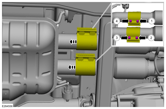 |
-
Disconnect the electrical connectors and detach the wire clips.
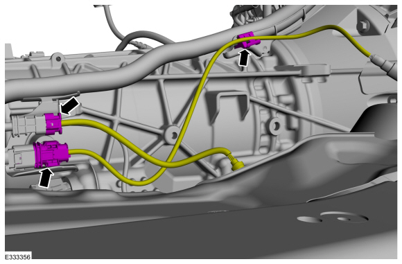 |
-
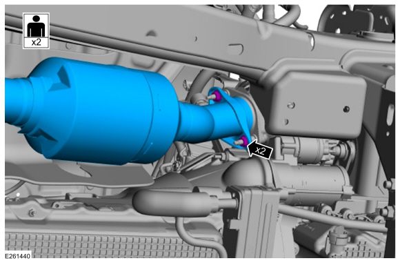
NOTE: Clean all exhaust connections before reassembly.
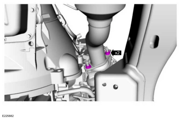
Remove and discard the catalytic converter nuts and remove the catalytic converter. Discard the gasket.
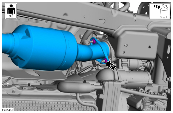 |
Rear Wheel Drive (RWD) vehicles
-
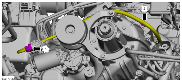
Remove the fuel line bracket bolt and push pin retainer.
 |
Four-Wheel Drive (4WD) vehicles
-
Remove the fuel line bracket bolt and push pin retainer, disconnect the transfer case vent tube.
 |
-
-
Disconnect the transfer case electrical connector.
-
Remove the wiring harness retainer and position aside.
-
Disconnect the transfer case electrical connector.
 |
All vehicles
-
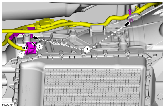
NOTICE: Do not pull on the wire harness to disconnect the electrical connector or damage to the electrical connector will occur.
-
Slide the lock tab.
-
Rotate lever to disconnect the transmission electrical connector.
-
Detach the retainer from the transmission.
-
Slide the lock tab.
 |
-
Remove the pin-type retainers and the access cover.
 |
-
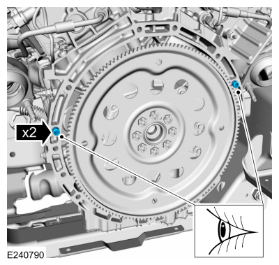
NOTE: Using the crankshaft pulley bolt, turn the engine clockwise.
-
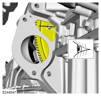
Index mark one stud and the flexplate for assembly reference.
-
Remove and discard the torque converter nuts.
-
Index mark one stud and the flexplate for assembly reference.
 |
-
Remove the lower bellhousing bolt.
 |
-
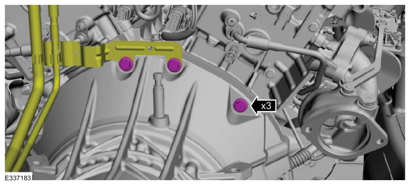
Remove the RH side bellhousing bolts.
 |
-
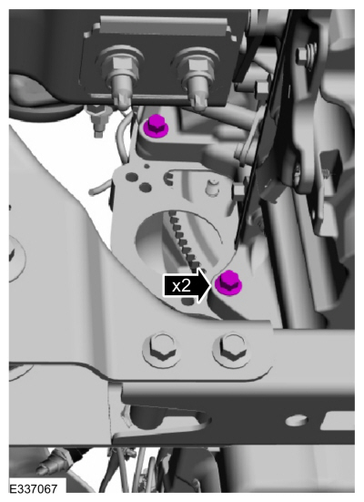
Remove the top bellhousing bolts and position aside the bracket.
 |
-
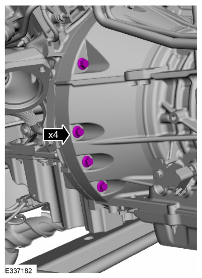
Remove the LH bellhousing bolts.
 |
-
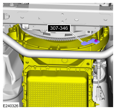
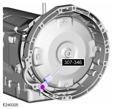
Slide the transmission back enough to install the special tool.
Use Special Service Tool: 307-346 (T97T-7902-A) Retainer, Torque Converter.
 |
Rear Wheel Drive (RWD) vehicles
-
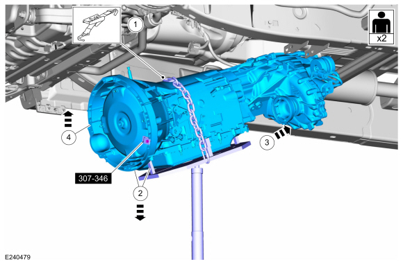
Using the high-lift transmission jack, remove the transmission from the vehicle.
Use the General Equipment: Transmission Jack
 |
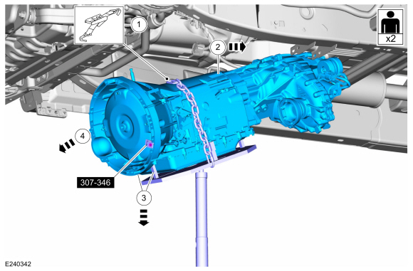
Four-Wheel Drive (4WD) vehicles
-
-
Make sure the transmission is securely fastened to the transmission jack.
-
Slide the transmission towards the rear of the vehicle.
-
Tilt the front of the transmission down.
-
Remove the transmission from the vehicle.
-
Make sure the transmission is securely fastened to the transmission jack.
 |
-
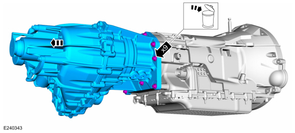
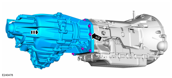
If the transmission is to be overhauled or if
installing a new or re-manufactured transmission, remove and discard the
bolts and separate the transfer case from the transmission.
 |
All vehicles
-
NOTICE: Failure to clean the transmission fluid cooler tubes can result in transmission failure.
If the transmission is to be overhauled or if installing a new or re-manufactured transmission, carry out the transmission fluid cooler backflushing and cleaning procedure.
Refer to: Transmission Fluid Cooler - Backflushing and Cleaning (307-02 Transmission Cooling, General Procedures).
Installation
-
Prior to installing a new transmission or an overhauled
transmission with a new main control, record the solenoid strategy
identification tag. If a new main control was installed, install the
replacement solenoid body tag over the original identification tag.
-
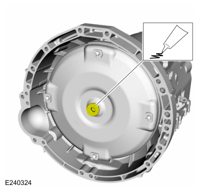
NOTICE: Prior to installation of the transmission, lubricate the torque converter pilot hub or damage to the torque converter or the engine crankshaft can occur.
Lubricate the torque converter pilot hub with multi-purpose grease.
Material: Motorcraft® Multi-Purpose Grease Spray / XL-5-A (ESB-M1C93-B)
 |
-
NOTICE: If the transmission is not positioned on the dowel pins, damage to the transmission may occur.
If the dowel pins were pulled out of the engine block during removal, install new dowel pins in the engine block.
 |
-
Install the special tool.
Use Special Service Tool: 307-346 (T97T-7902-A) Retainer, Torque Converter.
 |
-
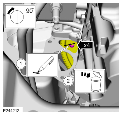
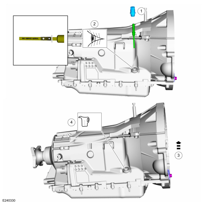
NOTE: If transmission is being replaced, remove the transmission fluid fill plug and verify that the transmission is filled with transmission fluid.
NOTE: If transmission was disassembled, add transmission fluid to the transmission.
NOTE: Rear Wheel Drive (RWD) shown, Four-Wheel Drive (4WD) similar.
-
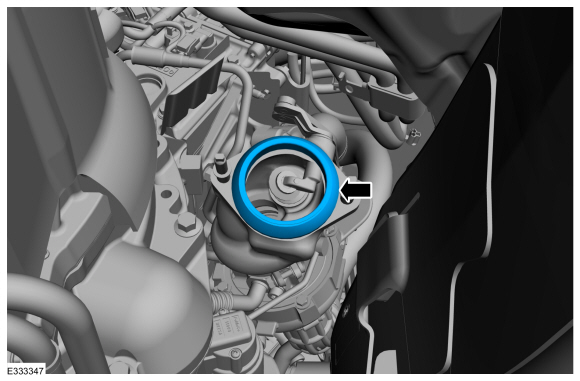
Remove the transmission fluid fill plug transmission fluid level indicator assembly.
-
Verify transmission is filled with transmission fluid.
-
Slightly tilt the transmission rearward.
-
If the transmission was disassembled, add 12.30L (13
qt) of transmission fluid to the transmission through the transmission
fluid fill hole.
Material: Motorcraft® MERCON® ULV Automatic Transmission Fluid / XT-12-QULV (WSS-M2C949-A, ) (MERCON® ULV)
-
Loosely install the transmission fluid plug when finished.
-
Remove the transmission fluid fill plug transmission fluid level indicator assembly.
 |
-
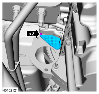
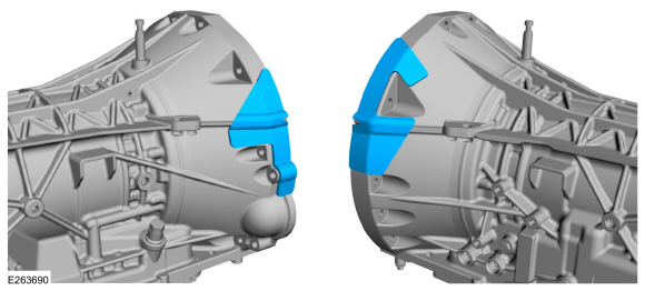
If installing a new or re-manufactured transmission, install the new stick on heat shields to the bellhousing.
 |
Four-Wheel Drive (4WD) vehicles
-
If removed, install the transfer case and the new bolts.
-
Tighten the bolts evenly in a star pattern.
Torque: 150 lb.in (17 Nm)
-
Tighten the bolts evenly in a star pattern.
 |
-
NOTICE: Secure the transmission to the transmission jack with a safety strap.
NOTE: Make sure the transmission jack makes contact on the outer ribs of the transmission fluid pan.
Using a high-lift transmission jack, support the transmission.
-
Make sure the transmission is securely fastened to the transmission jack.
Use the General Equipment: Transmission Jack
-
Tilt the front of the transmission down.
-
Slide the transmission towards the rear of the vehicle.
-
Raise the front of the transmission into a horizontal position.
-
Make sure the transmission is securely fastened to the transmission jack.
 |
Rear Wheel Drive (RWD) vehicles
-
NOTICE: Secure the transmission to the transmission jack with a safety strap.
NOTE: Make sure the transmission jack makes contact on the outer ribs of the transmission fluid pan.
Using a high-lift transmission jack, position the transmission in the vehicle.
Use the General Equipment: Transmission Jack
|
All vehicles
-
Remove the special tool.
Use Special Service Tool: 307-346 (T97T-7902-A) Retainer, Torque Converter.
|
-
Align the index-mark made during removal.
 |
-
NOTE: Make sure the torque converter is fully seated in the transmission before aligning the transmission to the engine.
NOTE: With the transmission in a horizontal position, move it toward the engine and position it on the dowel pins.
Position the bracket and install the top bellhousing bolts.
Torque: 35 lb.ft (48 Nm)
|
-
Install the LH bellhousing bolts.
Torque: 35 lb.ft (48 Nm)
|
-
Install the RH bellhousing bolts.
Torque: 35 lb.ft (48 Nm)
|
-
Install the lower bellhousing bolt.
Torque: 35 lb.ft (48 Nm)
|
-
NOTE: Using the crankshaft pulley bolt, turn the engine clockwise.
Install the new torque converter nuts.
Torque: 35 lb.ft (48 Nm)
 |
-
Install the access cover and the pin-type retainers.
|
-
-
Push the transmission electrical connector in.
-
Lock the tab to connect the transmission electrical connector.
-
Attach the wiring harness retainers in the transmission.
-
Push the transmission electrical connector in.
 |
Rear Wheel Drive (RWD) vehicles
-
Remove the fuel line bracket bolt and push pin retainer.
Torque: 26 lb.ft (35 Nm)
|
Four-Wheel Drive (4WD) vehicles
-
-
Connect the transfer case electrical connector.
-
Position the wiring harness and install the retainer.
-
Connect the transfer case electrical connector.
|
-
Connect the transfer case vent tube, install the push pin retainer and the fuel line bracket bolt.
Torque: 26 lb.ft (35 Nm)
|
All vehicles
-
NOTE: Make sure that new gasket is installed.
Install the new gasket.
 |
-
NOTE: Loosely install the new RH catalytic converter nuts. Do not tighten at this time.
Position the RH catalytic converter in the vehicle. Loosely install the new RH catalytic converter nuts.
 |
-
Install the transmission support insulator.
Refer to: Transmission Support Insulator (307-01 Automatic Transmission - 10-Speed Automatic Transmission – 10R80, Removal and Installation).
-
Install the LH catalytic converter.
Refer to: Catalytic Converter LH (309-00 Exhaust System - 3.5L EcoBoost (272kW/370PS), Removal and Installation).
-
NOTE: Evenly tighten the catalytic converter nuts.
Tighten the RH catalytic converter nuts.
Torque: 30 lb.ft ( 40 Nm)
 |
-
Connect the electrical connectors and attach the wire clips.
|
-
Tighten the clamps in the sequence shown
Torque: 35 lb.ft (48 Nm)
|
-
Install the retainers and heatshield.
Torque: 80 lb.in (9 Nm)
|
-
Install the rear driveshaft assembly.
Refer to: Rear Driveshaft (205-01 Driveshaft, Removal and Installation).
Four-Wheel Drive (4WD) vehicles
-
Install the front driveshaft assembly.
Refer to: Front Driveshaft (205-01 Driveshaft, Removal and Installation).
-
Check the transfer case fluid level.
Refer to: Transfer Case Draining and Filling (307-07B Transfer Case, General Procedures).
Rear Wheel Drive (RWD) vehicles
-
Install the new stabilizer bar bracket nuts.
Torque: 41 lb.ft (55 Nm)
 |
All vehicles
-
Position back the transmission fluid cooler tubes, install the nut and the retainer.
Torque: 124 lb.in (14 Nm)
|
-
Install the transmission fluid heat exchanger.
Refer to: Transmission Fluid Heat Exchanger (307-02 Transmission Cooling, Removal and Installation).
-
NOTE: If equipped with a underbody splash shield, do not install the splash shield at this time.
Install the starter motor assembly.
Refer to: Starter Motor (303-06 Starting System - 3.5L EcoBoost (272kW/370PS), Removal and Installation).
-
Connect the battery ground cable.
Refer to: Battery Disconnect and Connect (414-01 Battery, Mounting and Cables, General Procedures).
-
After completing the repairs, perform the Misfire
Monitor Neutral Profile Correction procedure using a diagnostic scan
tool.
-
If a new transmission or a new main control was installed, the solenoid body strategy must be updated.
Refer to: Transmission Strategy Download (307-01 Automatic Transmission - 10-Speed Automatic Transmission – 10R80, General Procedures).
-
If the transmission was overhauled, the adaptive drive cycle must be updated.
Refer to: Adaptive Learning Drive Cycle (307-01 Automatic Transmission - 10-Speed Automatic Transmission – 10R80, General Procedures).
-
While driving the vehicle, use the scan tool to verify that the TFT
has reached a temperature of 96.7ºC-102ºC (206ºF-215ºF). This will
circulate the transmission fluid through the torque converter and the
transmission fluid cooling system, eliminating any trapped air in the
transmission fluid cooling system.
-
Check the transmission fluid level
Refer to: Transmission Fluid Level Check (307-01 Automatic Transmission - 10-Speed Automatic Transmission – 10R80, General Procedures).
 Shift Solenoids (SS). Removal and Installation
Materials
Name
Specification
Motorcraft® MERCON® ULV Automatic Transmission FluidXT-12-QULV
WSS-M2C949-A, MERCON® ULV
Removal
NOTE:
If a new SS is installed, carry out the adaptive learning drive cycle procedure at the end of the repair...
 Transmission Fluid Auxiliary Pump. Removal and Installation
Removal
NOTE:
It is not necessary to remove the transmission fluid
filter to remove the transmission fluid auxiliary pump.
Remove the transmission fluid pan and gasket...
Other information:
Lincoln Navigator 2018-2026 Workshop Manual: Interior Rear View Mirror. Removal and Installation
Special Tool(s) / General Equipment Interior Trim Remover Removal NOTE: Removal steps in this procedure may contain installation details. Mirror Types Mirror type 1 Remove the interior rear view mirror...
Lincoln Navigator 2018-2026 Workshop Manual: Specifications
Engine Item Specification Displacement 3.5L Ecoboost (214 CID) No. of cylinders 6 Bore/stroke 92.5/86.7 mm (3.641/3.413 in) Firing order 1-4-2-5-3-6 Spark plug 12405 Spark plug gap 0...
Categories
- Manuals Home
- 4th Gen Lincoln Navigator Service Manual (2018 - 2026)
- Neutral Flat Tow Activation and Deactivation. General Procedures
- Windshield Washer Pump. Removal and Installation
- Body and Paint
- Telematics Control Unit (TCU) Module. Removal and Installation
- Head Up Display (HUD) Module Calibration. General Procedures
Front Driveshaft. Removal and Installation
Special Tool(s) / General Equipment
Crimping ToolMaterials
Name Specification Motorcraft® Premium Long-Life GreaseXG-1-E1 ESA-M1C75-B
Removal
With the vehicle in NEUTRAL, position the vehicle on a hoist.Refer to: Jacking and Lifting (100-02 Jacking and Lifting, Description and Operation).
Remove the bolts and the transmission shield.