Lincoln Navigator: Automatic Transmission - 10-Speed Automatic Transmission – 10R80 / Shift Solenoids (SS). Removal and Installation
Materials
| Name |
Specification |
Motorcraft® MERCON® ULV Automatic Transmission Fluid
XT-12-QULV |
WSS-M2C949-A,
MERCON® ULV
|
Removal
NOTE:
If a new SS is installed, carry out the adaptive learning drive cycle procedure at the end of the repair.
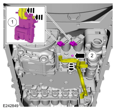
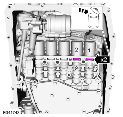
All Solenoids
-
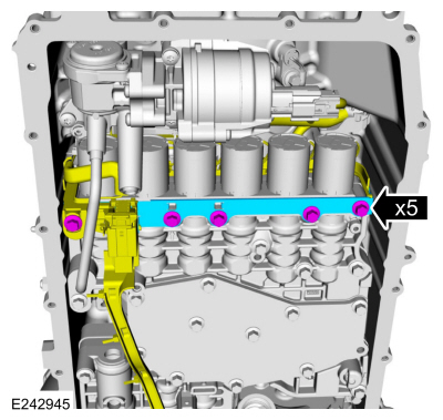
Remove the transmission fluid pan gasket and filter.
Refer to: Transmission Fluid Pan, Gasket and Filter (307-01 Automatic
Transmission - 10-Speed Automatic Transmission – 10R80, Removal and
Installation).
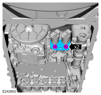
LPC (line pressure control) and TCC (torque converter clutch) Solenoids
-
-
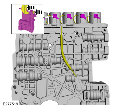
Slide the plastic lock to the unlock position.
While pressing the plastic tab, disconnect the electrical connector.
-
Disconnect the internal wiring harness retainer.
-
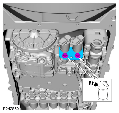
Remove and discard the bolts and remove the solenoid retaining plate.
-
Remove the solenoid(s) from the main control valve body.
-
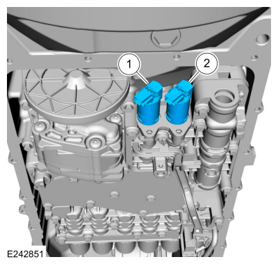
LPC solenoid (7G383)
-
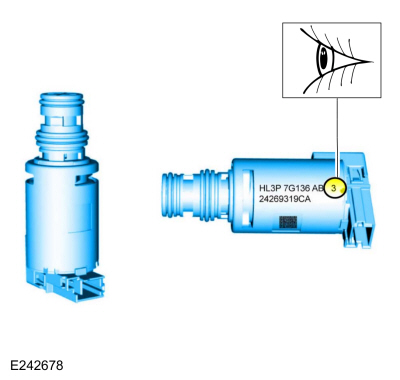
TCC solenoid (7G136)
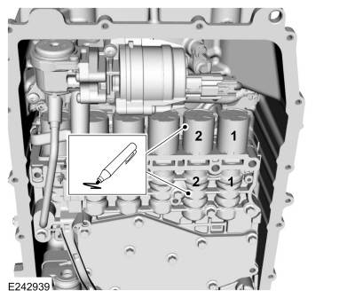
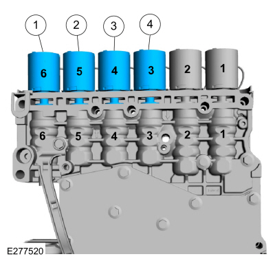
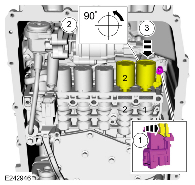
Solenoids D and E
-
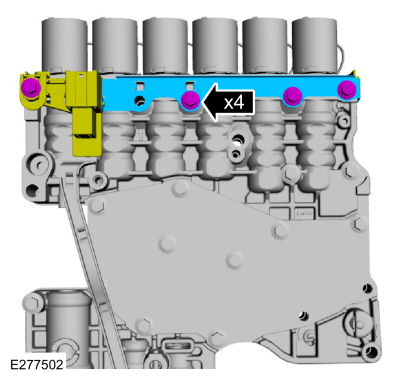
Remove the bolts and the shift solenoid retaining plate.
-
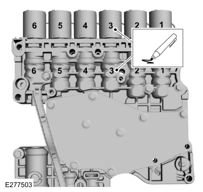
If replacing more then one solenoid, number the
solenoids and number the main control valve body solenoid ports to
correspond to the solenoid.
-
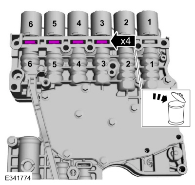
Remove and discard the shift solenoid retainer(s).
-
-
Slide the solenoid(s) out of the main control valve body bore.
-
Rotate the solenoid(s) in a clockwise direction.
-
Slide the plastic lock to the unlock position.
While pressing the plastic tab, disconnect the electrical connector.
-
Remove the solenoid(s) from the main control valve body.
-
SSE (7J136)
-
SSD (7J136)
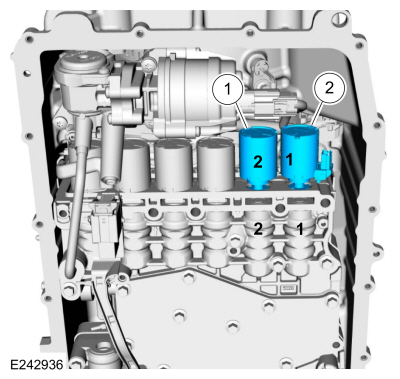
Solenoids A, B, C, and F
-
Remove the main control valve body.
Refer to: Main Control Valve Body (307-01 Automatic Transmission -
10-Speed Automatic Transmission – 10R80, Removal and Installation).
-
Remove the bolts and the shift solenoid retaining plate.
-
If replacing more then one solenoid, number the
solenoids and number the main control valve body solenoid ports to
correspond to the solenoid.
-
Remove and discard the shift solenoid retainer(s).
-
Slide the plastic lock to the unlock position. While
pressing the plastic tab, disconnect the electrical connector(s).
-
Remove the solenoid(s) from the main control valve body.
-
SSA (7J136)
-
SSF (7J136)
-
SSC (7J136)
-
SSB (7J136)
Installation
Solenoids A, B, C, and F
-
NOTICE:
Solenoids are calibrated from the factory and
are not all the same. To replace a solenoid, match the band number with
the original solenoid or harsh shifts or damage to the transmission can
occur.
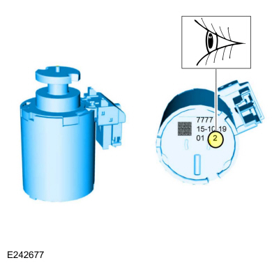
If new solenoids are needed, identify the solenoid band number.
-
Install the solenoid(s) in the main control valve body in the correct port(s) as marked during removal.
-
SSA (7J136)
-
SSF (7J136)
-
SSC (7J136)
-
SSB (7J136)
-
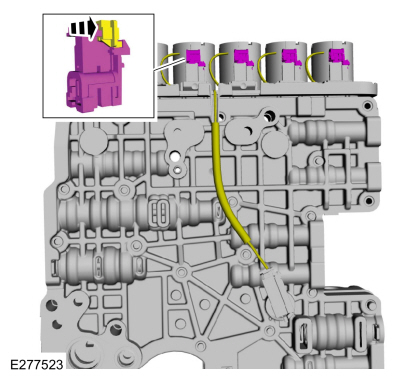
Connect the electrical connectors and slide the plastic lock to the locked position.
-
Install the new shift solenoid retainer(s) with the flat side towards the solenoids.
-
Retainer flat side
-
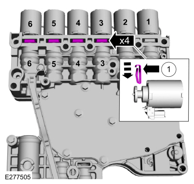
Install and the shift solenoid retaining plate and the bolts.
Torque:
106 lb.in (12 Nm)
-
Install the main control valve body.
Refer to: Main Control Valve Body (307-01 Automatic Transmission -
10-Speed Automatic Transmission – 10R80, Removal and Installation).
Solenoids D and E
-
NOTICE:
Solenoids are calibrated from the factory and
are not all the same. To replace a solenoid, match the band number with
the original solenoid or harsh shifts or damage to the transmission can
occur.
If new solenoids are needed, identify the solenoid band number.
-
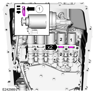
Install the solenoid(s) in the main control valve body in the correct port(s) as marked during removal.
-
SSE (7J136)
-
SSD (7J136)
-
-
Connect the electrical connectors and slide the plastic lock to the locked position.
-
Rotate the solenoid(s) in a counter-clockwise direction.
-
Slide the solenoid(s) into the main control valve body bore.
-
Install new shift solenoid retainer(s) with the flat side towards the solenoids.
-
Retainer flat side
-
Install and the shift solenoid retaining plate and the bolts.
Torque:
106 lb.in (12 Nm)
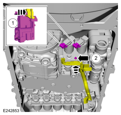
LPC (line pressure control) and TCC (torque converter clutch) Solenoids
-
NOTICE:
Solenoids are calibrated from the factory and
are not all the same. To replace a solenoid, match the replacement
solenoid type (normally high/normally low) and the band number with the
original solenoid or harsh shifts or damage to the transmission can
occur.
If new solenoids are needed, identify which type
(normally high/normally low) of solenoid it is and the solenoid band
number.
-
-
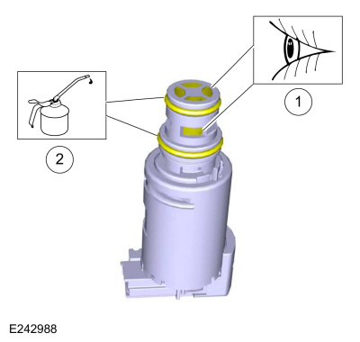
Inspect the solenoid screens for debris that may restrict fluid flow.
-
Lubricate the solenoid O-ring seals.
Material: Motorcraft® MERCON® ULV Automatic Transmission Fluid
/ XT-12-QULV
(WSS-M2C949-A, )
(MERCON® ULV)
-
Install the solenoid(s) in the main control valve body.
-
LPC solenoid (7G383)
-
TCC solenoid (7G136)
-
Install the solenoid retaining plate and the new bolts.
Torque:
80 lb.in (9 Nm)
-
-
Connect the electrical connectors and slide the plastic lock to the locked position.
-
Connect the internal wiring harness retainer.
All Solenoids
-
Install the transmission fluid pan gasket and filter.
Refer to: Transmission Fluid Pan, Gasket and Filter (307-01 Automatic
Transmission - 10-Speed Automatic Transmission – 10R80, Removal and
Installation).
-
If a new SS was installed, carry out the adaptive learning drive cycle procedure.
Refer to: Adaptive Learning Drive Cycle (307-01 Automatic Transmission -
10-Speed Automatic Transmission – 10R80, General Procedures).
Special Tool(s) /
General Equipment
307-549Installer, Shift Shaft Fluid SealTKIT-2005D1-F1
Removal
With the vehicle in NEUTRAL, position it on a hoist...
Special Tool(s) /
General Equipment
307-346
(T97T-7902-A)
Retainer, Torque ConverterTKIT-1998-LM (NavigatoR)TKIT-1997-F/FLM/LT
Transmission Jack
Materials
Name
Specification
Motorcraft® Multi-Purpose Grease SprayXL-5-A
ESB-M1C93-B
Motorcraft® MERCON® ULV Automatic Transmission FluidXT-12-QULV
WSS-M2C949-A, MERCON® ULV
..
Other information:
Removal
With the vehicle in NEUTRAL, position it on a hoist.
Refer to: Jacking and Lifting (100-02 Jacking and Lifting, Description and Operation).
Remove the air cleaner outlet pipe.
Refer to: Air Cleaner Outlet Pipe (303-12)
.
Remove the air cleaner.
Refer to: Air Cleaner (303-12)
.
Disconnect the electr..
Materials
Name
Specification
Motorcraft® Metal Brake Parts CleanerPM-4-A, PM-4-B, APM-4-C
-
Removal
NOTE:
Removal steps in this procedure may contain installation details.
NOTE:
Vehicles with mechanical parking brake shown, vehicles with electronic parking brake EPB similar.
WARNING:
Service actions on vehicles equipp..
 Selector Shaft Seal. Removal and Installation
 Transmission. Removal and Installation
 205-123
(T78P-1177-A)
205-123
(T78P-1177-A)
 308-047
(T77F-1102-A)
308-047
(T77F-1102-A)