Lincoln Navigator: Controller Area Network (CAN) Module Communications Network / Gateway Module A (GWM). Removal and Installation
Removal
NOTE: Removal steps in this procedure may contain installation details.
-
NOTE: If installing a new module, it is necessary to upload the module configuration information to the scan tool prior to removing the module. This information must be downloaded into the new module after installation.
Using a diagnostic scan tool, begin the PMI process for the GWM following the on-screen instructions.
-
Disconnect the battery.
Refer to: Battery Disconnect and Connect (414-01 Battery, Mounting and Cables, General Procedures).
-
Remove the LH C-Pillar trim panel.
Refer to: C-Pillar Trim Panel (501-05 Interior Trim and Ornamentation, Removal and Installation).
-
-
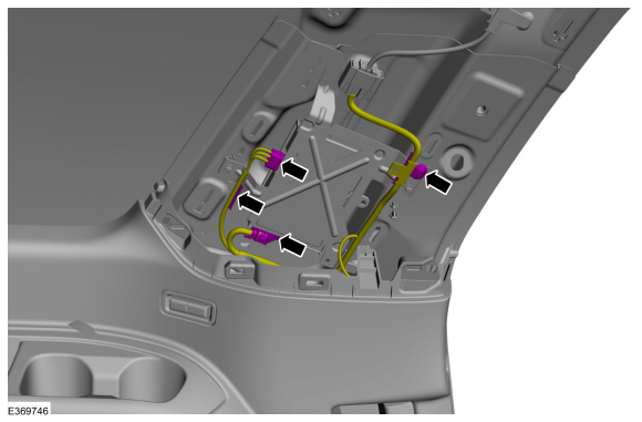
Disconnect the electrical connectors from the GWM .
-
Release the wire guides and position aside the wiring harness from the GWM bracket.
-
Disconnect the electrical connectors from the GWM .
 |
-
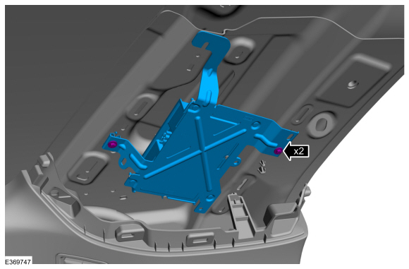
Remove the bolts and the GWM assembly.
Torque: 42 lb.in (4.8 Nm)
 |
-
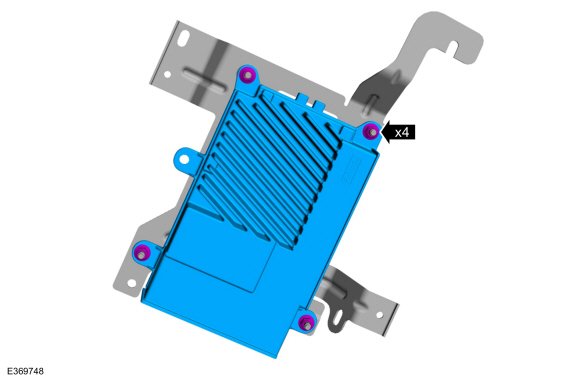
Remove the nuts and the GWM from the bracket.
Torque: 22 lb.in (2.5 Nm)
 |
Installation
-
To install, reverse the removal procedure.
-
NOTE: This step is only necessary when installing a new component.
Using a diagnostic scan tool, complete the PMI process for the GWM following the on-screen instructions.
 Controller Area Network (CAN) Module Communications Network. Diagnosis and Testing
Diagnostic Trouble Code (DTC) Chart
Diagnostics in this manual assume a certain skill level and knowledge of Ford-specific diagnostic practices. REFER to: Diagnostic Methods (100-00 General Information, Description and Operation)...

Other information:
Lincoln Navigator 2018-2026 Workshop Manual: Air Conditioning (A/C) System Recovery, Evacuation and Charging. General Procedures
Recovery NOTICE: Use an A/C refrigerant analyzer before recovering any of the vehicle's A/C refrigerant. Failure to do so puts the shop's bulk refrigerant at risk of contamination. If the vehicle's A/C refrigerant is contaminated, refer the customer to the service facility that carried out the last A/C service. If the customer wishes to pay the additional cost, use the A/C recovery ..
Lincoln Navigator 2018-2026 Workshop Manual: Third Row Double Seat Center Seatbelt Buckle. Removal and Installation
Removal NOTE: Removal steps in this procedure may contain installation details. Remove the third row double seat. Refer to: Third Row Seat (501-10C Third Row Seats, Removal and Installation). Remove the third row double seat center seatbelt buckle. If equipped. Detach the wiring harness retainer. If equipped. Detach and dis..
Categories
- Manuals Home
- 4th Gen Lincoln Navigator Service Manual (2018 - 2026)
- Front Bumper Cover. Removal and Installation
- Body Control Module (BCM). Removal and Installation
- Liftgate Trim Panel. Removal and Installation
- Rear View Mirrors - System Operation and Component Description. Description and Operation
- Neutral Flat Tow Activation and Deactivation. General Procedures
Rear Stabilizer Bar Link. Removal and Installation
Removal
NOTE: Removal steps in this procedure may contain installation details.
With the vehicle in NEUTRAL, position it on a hoist.Refer to: Jacking and Lifting (100-02 Jacking and Lifting, Description and Operation).
NOTE: Use the hex-holding feature to prevent the stud from turning while removing the nut.
Remove and discard the 2 rear stabilizer bar link nuts and remove the rear stabilizer bar link.Torque: 46 lb.ft (63 Nm)
