Lincoln Navigator: Climate Control System - General Information / Climate Control Housing. Disassembly and Assembly
DISASSEMBLY
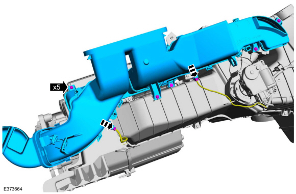
Air Inlet Housing
-
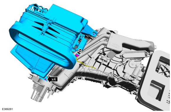
Remove the climate control housing.
Refer to: Climate Control Housing (412-00 Climate Control System - General Information, Removal and Installation).
-
Remove the retainers and remove the air inlet housing.
-
Disconnect the electrical connector.
-
Disconnect the electrical connector.
 |
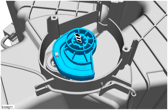
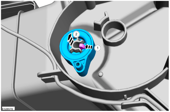
Blower Motor
-
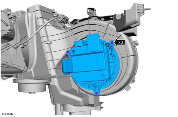
Remove the screws and the blower motor control module assembly.
 |
Heater Core
-
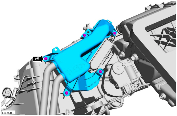
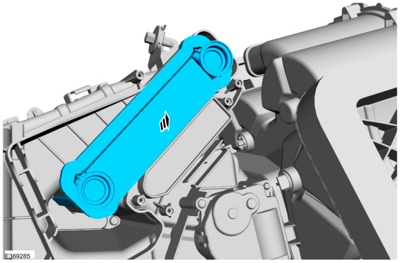
Remove the retainers and remove the heater core tube cover.
 |
-
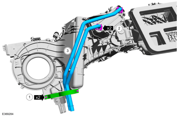
Remove the heater core tubes.
-
Remove the retaining clips.
-
Remove the screws and the tube tube clamp.
-
Remove the heater core tubes.
-
Remove the retaining clips.
 |
-
Remove the heater core.
 |
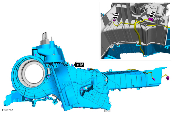
Air Distribution Housing
-
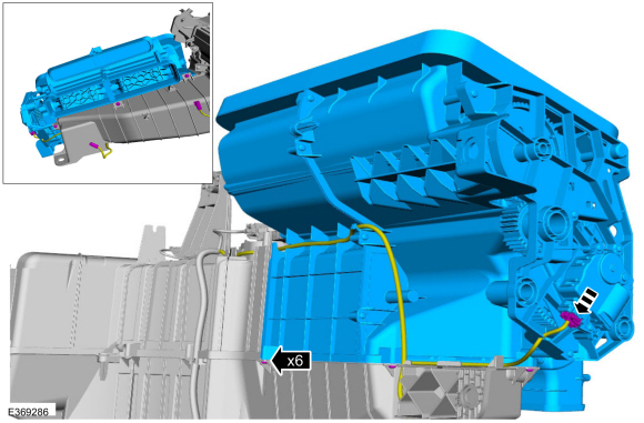
Remove the retainers and the air distribution housing.
-
Disconnect the electrical connector and position aside the electrical harness.
-
Disconnect the electrical connector and position aside the electrical harness.
 |
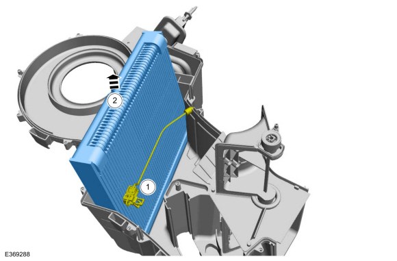
Evaporator
-
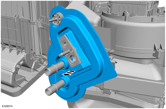
Remove the seal.
 |
-
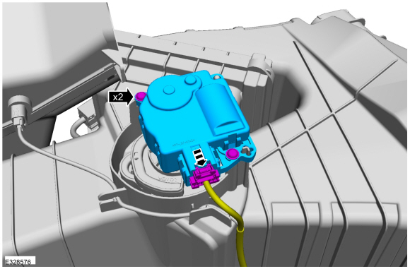
Remove the screws and the temperature door actuator.
-
Disconnect the electrical connector.
-
Disconnect the electrical connector.
 |
-
Remove the retainers and the floor duct.
-
Disconnect the electrical connectors.
-
Disconnect the electrical connectors.
 |
-
Remove the actuator cam.
 |
-
Remove the actuator cam.
-
NOTE: Exercise caution, retainers can be easily damaged.
Depress the tempreature door lever retainer.
-
Remove the tempreature door lever.
-
 |
-
Remove the retainers and the lower climate control housing case.
-
Disconnect the electrical connectors and position aside the harness.
-
Disconnect the electrical connectors and position aside the harness.
 |
-
Remove the evaporator assembly.
-
Postion aside the evaporator tempreature sensor.
-
Remove the evaporator assembly.
-
Postion aside the evaporator tempreature sensor.
 |
ASSEMBLY
-
To assembly, reverse the dissassembly procedure.
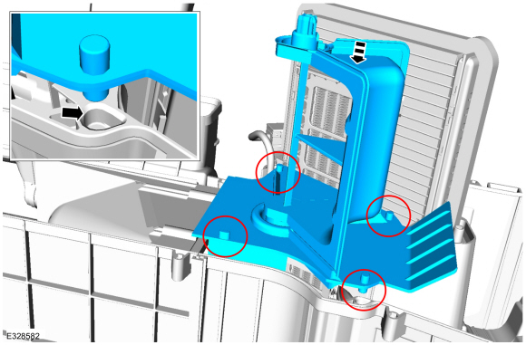
-
Make sure the divider plate dowls are properly aligned
and seated in the upper portion of the climate control housing before
installing the lower the portion of the climate control housing.
 |
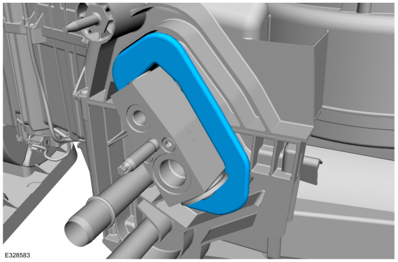
-
Make sure the TXV seal is properly seated aorund the TXV
once the upper and lower portions of the climate control housing are
reassembled.
 |
 Thermostatic Expansion Valve Manifold and Tube Assembly. Removal and Installation
Special Tool(s) /
General Equipment
Flat Headed Screw Driver
Locking Pliers
Removal
NOTICE:
During the removal of components, cap, tape or otherwise
appropriately protect all openings to prevent the ingress of dirt or
other contamination...

Other information:
Lincoln Navigator 2018-2026 Workshop Manual: Steering Column Upper Shaft. Removal and Installation
Removal NOTE: Removal steps in this procedure may contain installation details. NOTE: Do not allow the steering column to rotate while the steering column shaft is disconnected or damage to the steering column internal sensor may result. NOTE: Use a steering wheel holding device (such as Hunter® 28-75-1 or equivalent). Keep the steering wheel in the s..
Lincoln Navigator 2018-2026 Workshop Manual: Engine Mount LH. Removal and Installation
Special Tool(s) / General Equipment 303-1246Engine Spreader BarTKIT-2006UF-FLMTKIT-2006UF-ROW 303-1654Lift Eyes 303-F070Support Bar, EngineTKIT-1999A-F/LTTKIT-1999A-FM/FLM Vehicle/Axle Stands Removal NOTICE: Use care when positioning the front axle housing or the vacuum lines to the axle solenoid may become disconnected or damaged. ..
Categories
- Manuals Home
- 4th Gen Lincoln Navigator Service Manual (2018 - 2026)
- Transmission Fluid Drain and Refill. General Procedures
- Transmission Fluid Level Check. General Procedures
- Power Running Board (PRB). Diagnosis and Testing
- Windshield Washer Pump. Removal and Installation
- Rear View Mirrors - System Operation and Component Description. Description and Operation
Differential Case Runout Check. General Procedures
Special Tool(s) / General Equipment
 205-1016
Installer, Differential Bearing
TKIT-2014D-ROW2
TKIT-2014D-FL_ROW
 205-153
(T80T-4000-W)
205-153
(T80T-4000-W)
Handle
 205-D061
(D83T-4205-C2)
205-D061
(D83T-4205-C2)
Step Plate Dial Indicator Three Leg Puller Punch