Lincoln Navigator: Automatic Transmission - 10-Speed Automatic Transmission – 10R80 / Transmission Internal Wiring Harness. Removal and Installation
Special Tool(s) /
General Equipment
 |
307-746
Remover, Transmission Wiring Harness Connector |
Removal
-
Remove the main control valve body.
Refer to: Main Control Valve Body (307-01 Automatic Transmission -
10-Speed Automatic Transmission – 10R80, Removal and Installation).
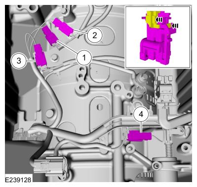
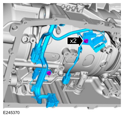
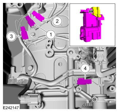
Main Control Valve Body Harness
-
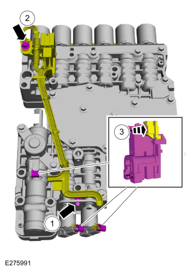
Disconnect the internal wiring harness.
-
Slide the plastic lock to the unlock position. Disconnect the TCC
solenoid and the LPC solenoid electrical connectors. If equipped,
disconnect the park lock pawl solenoid electrical connector.
-
Remove internal wiring harness retaining bolt.
-
Disconnect the internal wiring harness retainer.
-
Disconnect the internal wiring harness electrical connectors.
-
Slide the plastic lock to the unlock position.
While pressing the plastic tab, disconnect the electrical connector.
-
Release the retainer and remove the internal wiring harness assembly.
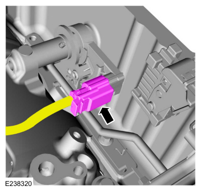
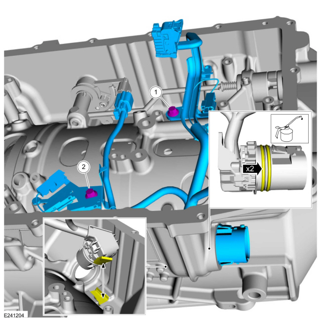
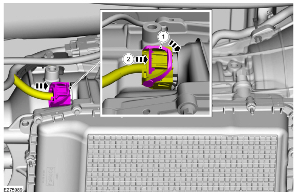
Transmission Case Harness
-
-
Slide the safety lock out.
-
Press the connector tab in.
-
Rotate the locking arm up and disconnect the transmission electrical connector.
-
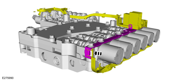
NOTE:
To disconnect the electrical connectors, slide
the plastic lock to the unlocked position. While pressing the plastic
tab, disconnect the electrical connector.
Unlock and disconnect the speed sensors.
-
TSS sensor
-
Intermediate speed A sensor
-
Intermediate speed B sensor
-
OSS sensor
-
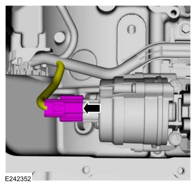
Disconnect the TR sensor electrical connector.
-
If equipped, disconnect the transmission fluid auxiliary pump electrical connector.
-
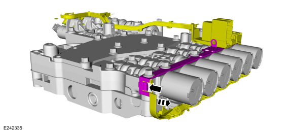
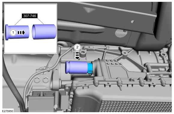
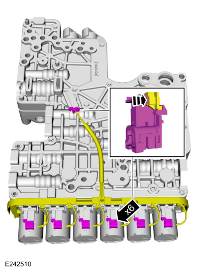
-
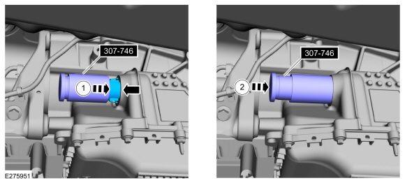
Assemble the special tool.
Use Special Service Tool: 307-746
Remover, Transmission Wiring Harness Connector.
-
Position the special tool onto the transmission internal wiring harness connector.
-
Using the special tool, disconnect the transmission
internal wiring harness connector from the transmission case.
-
Slide the special tool over the connector flush with the transmission case.
Use Special Service Tool: 307-746
Remover, Transmission Wiring Harness Connector.
-
Use the special tool to push the connector through the transmission case.
-
Remove the bolts and the transmission internal wiring harness.
Installation
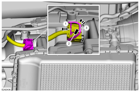
Transmission Case Harness
-
Install the wiring harness. Lubricate the O-ring
seals with petroleum jelly. Align the tab on the electrical connector
with the indention in the transmission case and install the main
electrical connector in the transmission case. Align the wiring harness
and install the bolts.
-
Torque:
97 lb.in (11 Nm)
-
Torque:
106 lb.in (12 Nm)
-
If equipped, connect the transmission fluid auxiliary pump electrical connector.
-
Support the opposite side of the TR sensor and connect the electrical connector.
-
NOTE:
After connecting the electrical connectors, slide the plastic lock to the locked position.
Connect and lock the speed sensors.
-
TSS sensor
-
Intermediate speed A sensor
-
Intermediate speed B sensor
-
OSS sensor
-
-
Rotate the locking arm down and connect the transmission electrical connector.
-
Slide the safety lock in.
Main Control Valve Body Harness
-
Install the internal wiring harness assembly and attach the retainer.
-
Connect the internal wiring harness electrical connectors.
-
Slide the plastic lock to the locked position.
-
Connect the internal wiring harness.
-
Connect the internal wiring harness retainer.
-
Install the internal wiring harness retaining bolt.
Torque:
106 lb.in (12 Nm)
-
Connect the TCC solenoid and the LPC
solenoid electrical connectors. If equipped, connect the park lock
pawl solenoid electrical connector. Slide the plastic lock to the locked
position.
All Harnesses
-
Install the main control valve body.
Refer to: Main Control Valve Body (307-01 Automatic Transmission -
10-Speed Automatic Transmission – 10R80, Removal and Installation).
Removal
Remove the main control valve body.
Refer to: Main Control Valve Body (307-01 Automatic Transmission -
10-Speed Automatic Transmission – 10R80, Removal and Installation)...
Special Tool(s) /
General Equipment
307-783Installer, Roll Pin
Rubber Mallet
Punch
Removal
Remove the main control valve body...
Other information:
Removal
NOTE:
Removal steps in this procedure may contain installation details.
Remove the front bumper cover.
Refer to: Front Bumper Cover (501-19 Bumpers, Removal and Installation).
Remove the front bumper nuts...
Removal
NOTE:
Removal steps in this procedure may contain installation details.
Remove the fuel tank.
Refer to: Fuel Tank (310-01 Fuel Tank and Lines - 3.5L EcoBoost (272kW/370PS), Removal and Installation).
Remove three nuts and remove the support guard...
 Transmission Fluid Temperature (TFT) Sensor. Removal and Installation
 Transmission Range (TR) Sensor. Removal and Installation