Lincoln Navigator: Automatic Transmission - 10-Speed Automatic Transmission – 10R80 / Transmission Range (TR) Sensor. Removal and Installation
Special Tool(s) /
General Equipment
 |
307-783
Installer, Roll Pin |
| Rubber Mallet |
| Punch |
Removal
-
Remove the main control valve body.
Refer to: Main Control Valve Body (307-01 Automatic Transmission -
10-Speed Automatic Transmission – 10R80, Removal and Installation).
-
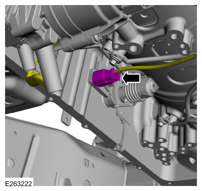
Disconnect the TR sensor electrical connector and position the transmission wiring harness aside.
-
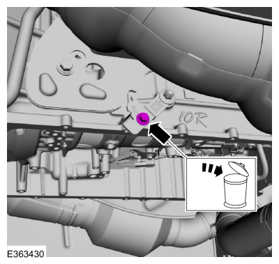
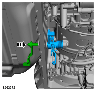
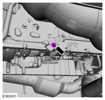
Remove and discard the park override lever bolt (7P219).
-
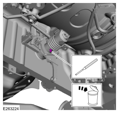
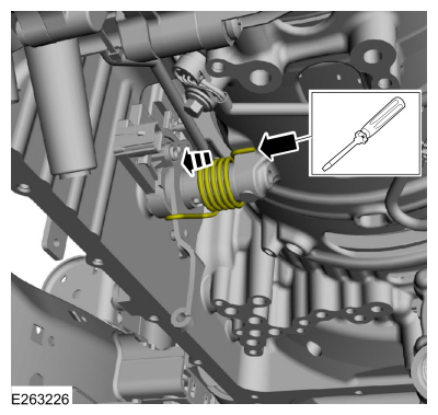
Using a punch, remove and discard the manual shaft-to-TR sensor roll pin (7G100).
Use the General Equipment: Punch
-
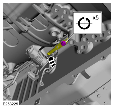
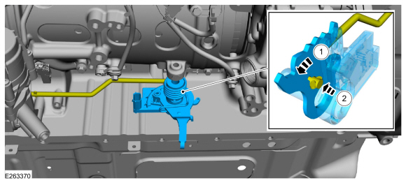
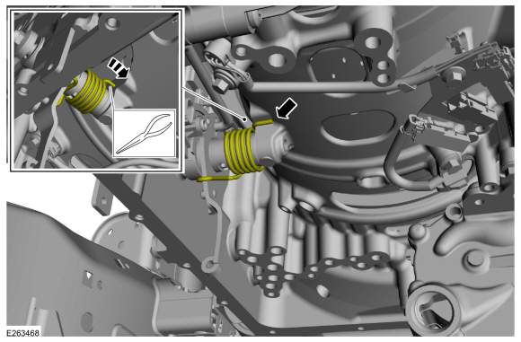
Loosen the detent spring bolt and the detent spring enough to remove the tension from the TR sensor.
-
Release the tension from the park return spring.
-
Slide the end of the park return spring off the transmission case.
-
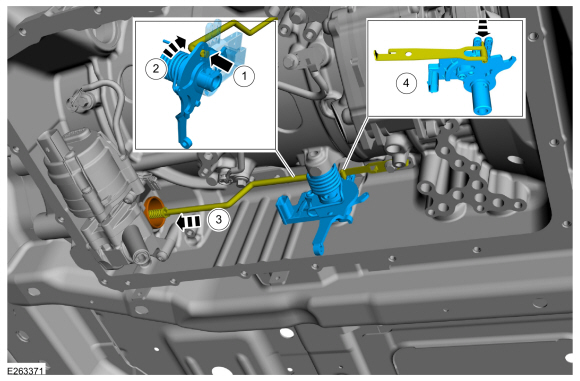
Remove the manual shaft and park override lever from the TR sensor.
-
Remove the TR sensor (7H557).
-
Rotate the TR sensor.
-
Disconnect the park pawl actuator rod and remove the TR sensor.
Installation
-
Install the TR sensor (7H557).
-
Connect the park pawl actuator rod to the TR sensor.
-
Rotate the TR sensor.
-
Position the park pawl actuator rod into the park pawl sleeve.
-
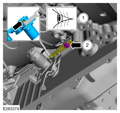
Align the TR sensor to the detent spring.
-
Slide the manual shaft and park override lever into the TR sensor.
-
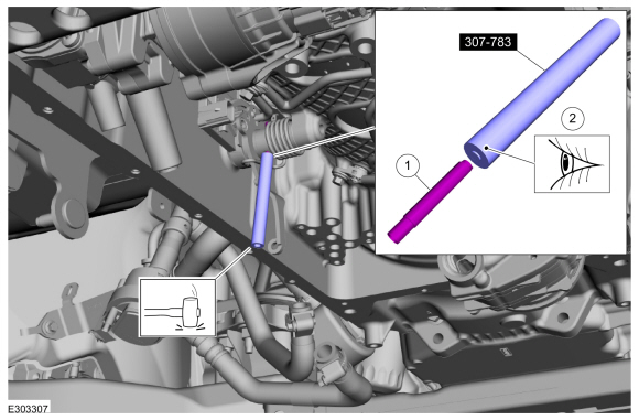
Using the dimpled end of the special tool, install the new manual shaft-to-TR sensor roll pin flush with the shaft.
-
New roll pin
-
Dimpled end of special tool
Use Special Service Tool: 307-783
Installer, Roll Pin.
Use the General Equipment: Rubber Mallet
-
-
Align the detent spring in the center of the TR sensor.
-
Torque:
97 lb.in (11 Nm)
-
Slide the end of the park return spring onto the transmission case.
-
Install a new park override lever bolt.
Torque:
177 lb.in (20 Nm)
-
Connect the TR sensor electrical connector.
-
Install the main control valve body.
Refer to: Main Control Valve Body (307-01 Automatic Transmission -
10-Speed Automatic Transmission – 10R80, Removal and Installation).
Special Tool(s) /
General Equipment
307-746Remover, Transmission Wiring Harness Connector
Removal
Remove the main control valve body...
Removal
With the vehicle in NEUTRAL, position it on a hoist.
Refer to: Jacking and Lifting (100-02 Jacking and Lifting, Description and Operation)...
Other information:
Special Tool(s) /
General Equipment
100-002
(TOOL-4201-C)
Holding Fixture with Dial Indicator Gauge
205-001
(TOOL-4000-E)
Spreader, Differential Carrier
205-005
(T53T-4621-C)
Installer, Drive Pinion Bearing Cone
205-010
(T57L-4221-A2)
Installer, Differential Side Bearing
205-024
(T67P-4616-A)
Installer, Drive Pinion Bearin..
Item
Description
1
BCM
2
Rear keyless entry/PATS antenna
3
RTM
4
PATS center antenna
..

 Transmission Internal Wiring Harness. Removal and Installation
 Transmission Support Insulator. Removal and Installation