Lincoln Navigator: Engine - 3.5L EcoBoost (272kW/370PS) / Timing Chain. Removal and Installation
Special Tool(s) /
General Equipment
 |
303-1655
Tool, Camshaft Holding |
Removal
NOTICE:
During engine repair procedures, cleanliness is extremely
important. Any foreign material, including any material created while
cleaning gasket surfaces, that enters the oil passages, coolant passages
or the oil pan may cause engine failure.
RH and LH timing chains
-
Remove the engine front cover.
Refer to: Engine Front Cover (303-01 Engine - 3.5L EcoBoost (272kW/370PS), Removal and Installation).
Refer to: Engine Front Cover (303-01 Engine - 3.5L EcoBoost (272kW/370PS), Removal and Installation).
RH timing chain
-
Install the crankshaft pulley bolt.
-
-
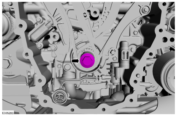
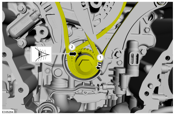
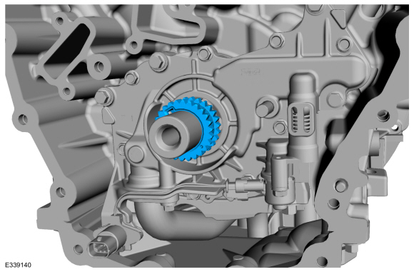
Rotate the crankshaft clockwise.
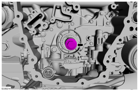
-
Position the crankshaft sprocket keyway at the 11 o'clock position.
-
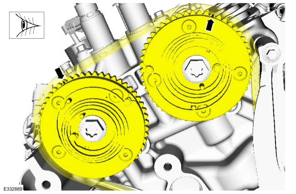
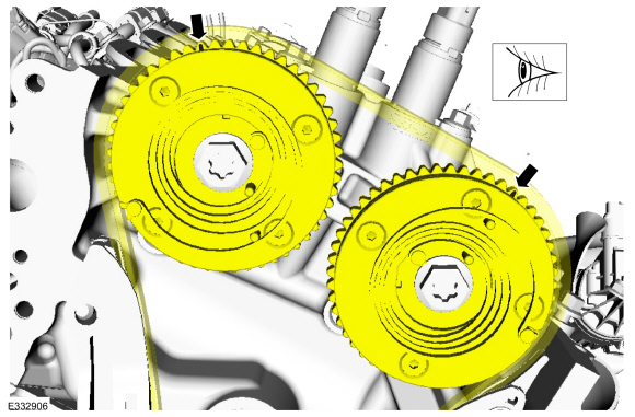
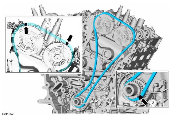
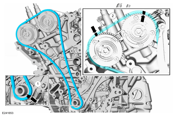
Verify the timing marks on the VCT units are at the positions shown.
-
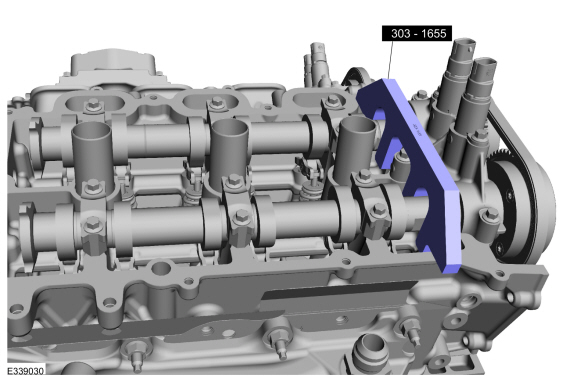
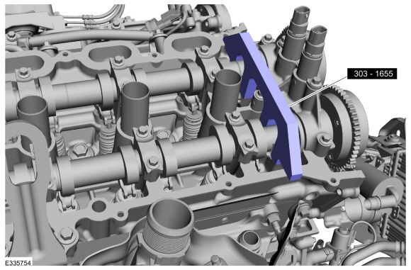
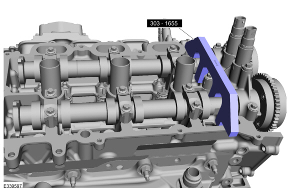
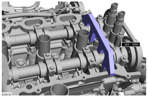
NOTE:
The Camshaft Holding Tool will hold the camshafts in the TDC position.
Install Special Service Tool: 303-1655
Tool, Camshaft Holding.
-
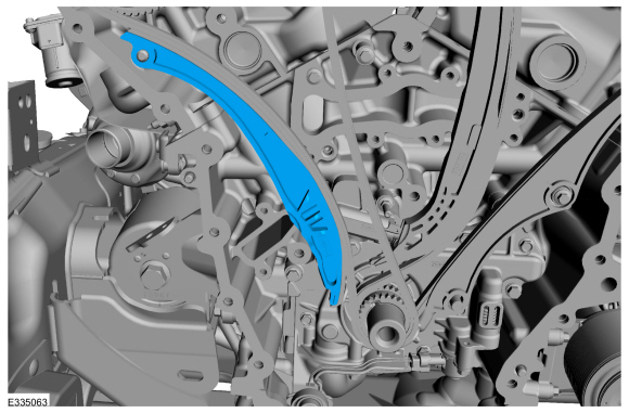
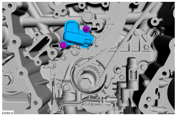
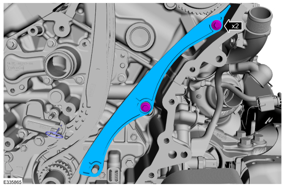
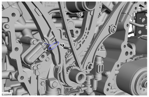
Remove the bolts and the RH timing chain guide.
-
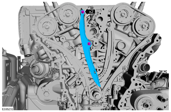
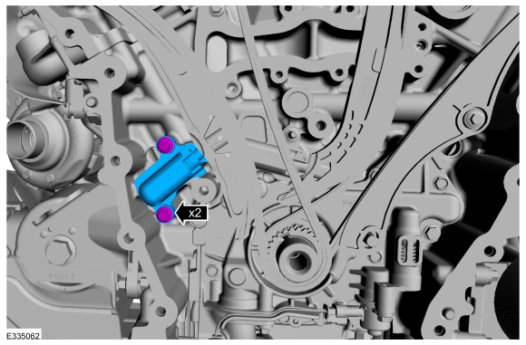
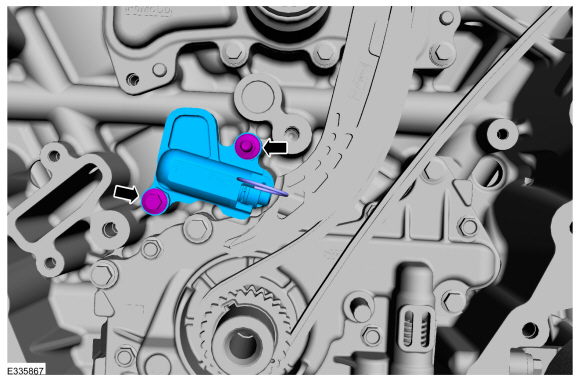
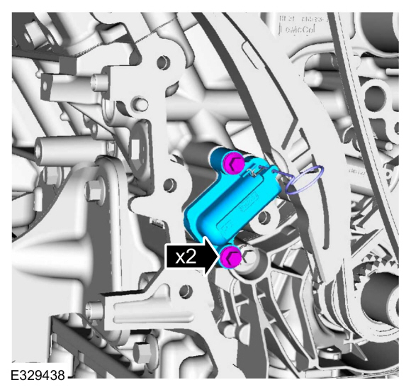
Remove the bolts and the RH timing chain tensioner.
-
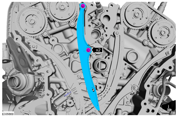
Remove the RH timing chain tensioner arm.
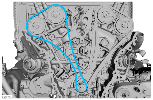
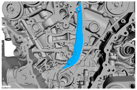
-
Remove the RH timing chain.
LH timing chain
-
NOTE:
The Camshaft Holding Tool will hold the camshafts in the TDC position.
Remove Special Service Tool: 303-1655
Tool, Camshaft Holding.
-
Verify the timing marks on the VCT units are at the positions shown.
-
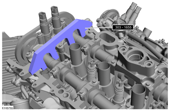
NOTE:
The Camshaft Holding Tool will hold the camshafts in the TDC position.
Install Special Service Tool: 303-1655
Tool, Camshaft Holding.
-
Remove the bolts and the LH timing chain guide.
-
Remove the studbolt, bolt and the LH timing chain tensioner.
-
Remove the LH timing chain tensioner arm.
-
Remove the LH timing chain.
-
Remove the crankshaft pulley bolt.
-
Remove the timing chain sprocket.
Installation
LH timing chain
-
Install the timing chain sprocket.
-
NOTE:
The crankshaft sprocket is reversible with a
timing mark on each face. For installation of each timing chain, utilize
the timing mark on the front face of the crankshaft sprocket for chain
alignment.
-
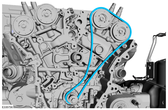
Install the LH timing chain with the single colored links aligned with the timing marks on the VCT units.
-
Install the double colored links so they straddle the timing mark on the crankshaft sprocket.
-
Install the LH timing chain tensioner arm.
-
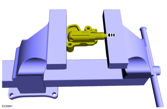
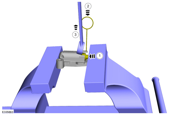
Position the tensioner in a soft-jawed vise.
-
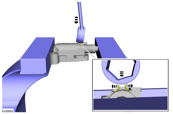
NOTE:
Use of a commercially available tools with a
curved radius in the range of 10mm - 15mm is suggested for use in
resetting the ratchet clip. Examples are a 8mm closed end wrench,
12x12mm piece of bar stock, T40 to T50 Torx screwdriver or 3/8 wobble
style socket extender.
Using a commercially available wrench, push down on the ratchet clip so the ratchet clip pushes outward.
-
-
Using the soft-jawed vise, compress the piston to the reset position.
-
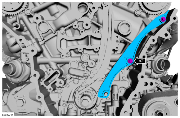
Install a locking pin in the 2 holes of the tensioner body to hold the piston in place.
-
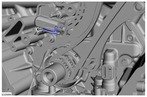
Remove the commercially available tool and the tensioner.
-
Position the LH timing chain tensioner with the end of the tensioner
correctly engaged to the tensioner arm and install the fasteners.
Torque:
Stage 1:
89 lb.in (10 Nm)
Stage 2:
30°
-
Install the LH timing chain guide and bolts.
Torque:
Stage 1:
89 lb.in (10 Nm)
Stage 2:
30°
-
Remove the tensioner pins.
-
Remove Special Service Tool: 303-1655
Tool, Camshaft Holding.
-
Install Special Service Tool: 303-1655
Tool, Camshaft Holding.
RH timing chain
-
NOTE:
The crankshaft sprocket is reversible with a
timing mark on each face. For installation of each timing chain, utilize
the timing mark on the front face of the crankshaft sprocket for chain
alignment.
-
Install the RH timing chain with the single colored links aligned with the timing marks on the VCT units.
-
Install the double colored links so they straddle the timing mark on the crankshaft sprocket.
-
Install the RH timing chain tensioner arm.
-
Position the tensioner in a soft-jawed vise.
-
NOTE:
Use of a commercially available tools with a
curved radius in the range of 10mm - 15mm is suggested for use in
resetting the ratchet clip. Examples are a 8mm closed end wrench,
12x12mm piece of bar stock, T40 to T50 Torx screwdriver or 3/8 wobble
style socket extender.
Using a commercially available wrench, push down on the ratchet clip so the ratchet clip pushes outward.
-
-
Using the soft-jawed vise, compress the piston to the reset position.
-
Install a locking pin in the 2 holes of the tensioner body to hold the piston in place.
-
Remove the commercially available tool and the tensioner.
-
Position the RH timing chain tensioner with the end of the tensioner
correctly engaged to the tensioner arm and install the fasteners.
Torque:
Stage 1:
89 lb.in (10 Nm)
Stage 2:
30°
-
Install the RH timing chain guide and bolts.
Torque:
Stage 1:
89 lb.in (10 Nm)
Stage 2:
30°
-
Remove the tensioner pins.
-
Remove Special Service Tool: 303-1655
Tool, Camshaft Holding.
RH and LH timing chains
-
Install the engine front cover.
Refer to: Engine Front Cover (303-01 Engine - 3.5L EcoBoost (272kW/370PS), Removal and Installation).
Refer to: Engine Front Cover (303-01 Engine - 3.5L EcoBoost (272kW/370PS), Removal and Installation).
Special Tool(s) /
General Equipment
303-1633Remover, Roller Rocker FollowerTKIT-2014D-ROW3TKIT-2014D-FL_ROW
303-1633-01Remover, Roller Rocker Follower
Removal
NOTE:
This procedure should be used when removing and replacing
the clipped roller finger follower or hydraulic lash adjuster and the
camshafts are not removed...
Special Tool(s) /
General Equipment
303-1655Tool, Camshaft Holding
Removal
NOTICE:
During engine repair procedures, cleanliness is extremely
important...
Other information:
Removal
NOTE:
Removal steps in this procedure may contain installation details.
Remove the steering column shrouds.
Refer to: Steering Column Shrouds (501-05 Interior Trim and Ornamentation, Removal and Installation).
Remove the steering column control switch retainer...
Overview
NOTICE:
Do not use leaded fuel in a vehicle equipped with a
catalytic converter. In a vehicle that is continually misfueled, the
lead in the fuel will be deposited in the catalytic converter and
completely blanket the catalyst. Lead reacts with platinum to "poison"
the catalyst...

 Rocker Arm. Removal and Installation
 Timing Chain Tensioner. Removal and Installation