Lincoln Navigator: Engine - 3.5L EcoBoost (272kW/370PS) / Rocker Arm. Removal and Installation
Special Tool(s) / General Equipment
 |
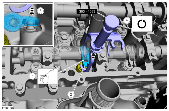
303-1633 Remover, Roller Rocker Follower TKIT-2014D-ROW3 TKIT-2014D-FL_ROW |
 |
303-1633-01 Remover, Roller Rocker Follower |
Removal
NOTE: This procedure should be used when removing and replacing the clipped roller finger follower or hydraulic lash adjuster and the camshafts are not removed.
LH side rocker arm
-
Remove the LH valve cover.
Refer to: Valve Cover LH (303-01 Engine - 3.5L EcoBoost (272kW/370PS), Removal and Installation).
-
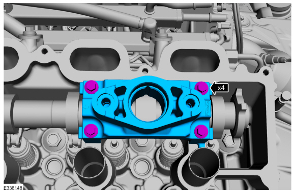
NOTE: This step only necessary if the pedestal cap needs to be removed to access the clipped roller finger followers.
Remove the bolts and the pedestal cap.
 |
-
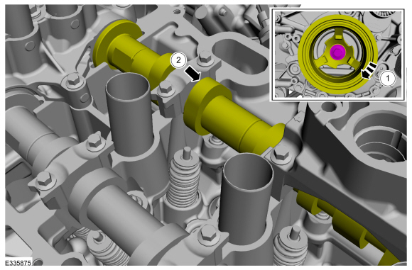
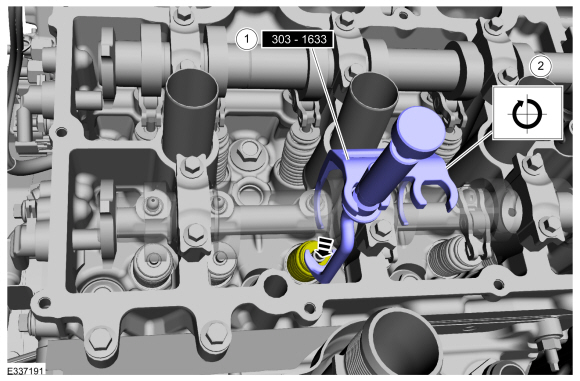
Rotate the crankshaft pulley bolt clockwise to
position the camshaft lobe upward for the clipped roller finger follower
to be removed.
 |
-
Remove the clipped roller finger follower. Repeat
steps for any other clipped roller finger follower that needs to be
removed.
 |
RH side rocker arm
-
Remove the valve cover.
Refer to: Valve Cover RH (303-01 Engine - 3.5L EcoBoost (272kW/370PS), Removal and Installation).
Refer to: Valve Cover RH (303-01 Engine - 3.5L EcoBoost (272kW/370PS), Removal and Installation).
-
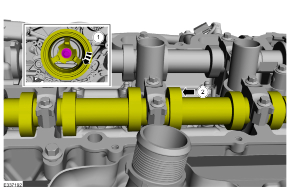
Rotate the crankshaft pulley bolt clockwise to
position the camshaft lobe upward for the clipped roller finger follower
to be removed.
 |
-
-
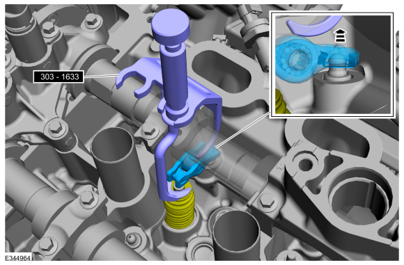
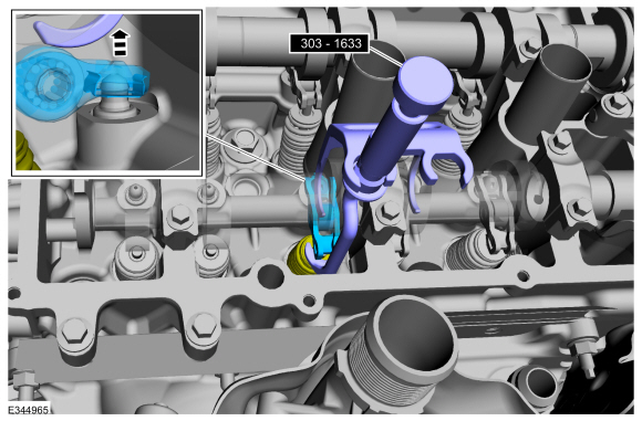
Install Special Service Tool: 303-1633 Remover, Roller Rocker Follower. , 303-1633-01 Remover, Roller Rocker Follower.
-
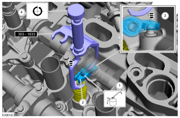
Turn the knob on the special tool clockwise to depress the valve and spring.
-
 |
-
Remove the clipped roller finger follower. Repeat
steps for any other clipped roller finger follower that needs to be
removed.
 |
Installation
LH side rocker arm
-
-
Lubricate the clipped roller finger follower with clean engine oil.
Refer to: Specifications (303-01C) .
-
Install the clipped roller finger follower.
-
Assemble the clipped roller finger follower spring clip onto the hydraulic lash adjuster.
-
Turn the knob on the special tool counterclockwise to raise the valve and spring.
Remove Special Service Tool: 303-1633 Remover, Roller Rocker Follower. , 303-1633-01 Remover, Roller Rocker Follower.
-
Repeat steps for any remaining clipped roller finger follower removed.
-
Lubricate the clipped roller finger follower with clean engine oil.
 |
-
NOTE: This step only necessary if the pedestal cap was removed.
-
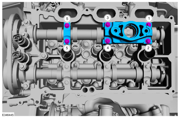
If removed, install the pedestal cap and the bolts.
Torque:
Stage 1: 1 thru 4: 71 lb.in (8 Nm)
Stage 2: 1 thru 4: 11°
Stage 3: Loosen 1 and 2: Loosen: turn(s)
Stage 4: 1 and 2: 71 lb.in (8 Nm)
Stage 5: 1 and 2: 11°
Stage 6: Loosen 5 and 6: Loosen: turn(s)
Stage 7: 5 and 6: 71 lb.in (8 Nm)
Stage 8: 5 and 6: 11°
Stage 9: Loosen 3 and 4: Loosen: turn(s)
Stage 10: 3 and 4: 71 lb.in (8 Nm)
Stage 11: 3 and 4: 11°
-
If removed, install the pedestal cap and the bolts.
 |
-
Install the LH valve cover.
Refer to: Valve Cover LH (303-01 Engine - 3.5L EcoBoost (272kW/370PS), Removal and Installation).
RH side rocker arm
-
-
Lubricate the clipped roller finger follower with clean engine oil.
Refer to: Specifications (303-01C) .
-
Install the clipped roller finger follower.
-
Assemble the clipped roller finger follower spring clip onto the hydraulic lash adjuster.
-
Turn the knob on the special tool counterclockwise to raise the valve and spring.
Remove Special Service Tool: 303-1633 Remover, Roller Rocker Follower. , 303-1633-01 Remover, Roller Rocker Follower.
-
Repeat steps for any remaining clipped roller finger follower removed.
-
Lubricate the clipped roller finger follower with clean engine oil.
 |
-
Install the RH valve cover.
Refer to: Valve Cover RH (303-01 Engine - 3.5L EcoBoost (272kW/370PS), Removal and Installation).
Refer to: Valve Cover RH (303-01 Engine - 3.5L EcoBoost (272kW/370PS), Removal and Installation).
 Oil Pump. Removal and Installation
Special Tool(s) /
General Equipment
303-1655Tool, Camshaft Holding
Vehicle/Axle Stands
Materials
Name
Specification
Motorcraft® High Performance Engine RTV SiliconeTA-357
WSE-M4G323-A6
Removal
NOTICE:
During engine repair procedures, cleanliness is extremely
important...
 Timing Chain. Removal and Installation
Special Tool(s) /
General Equipment
303-1655Tool, Camshaft Holding
Removal
NOTICE:
During engine repair procedures, cleanliness is extremely
important...
Other information:
Lincoln Navigator 2018-2026 Workshop Manual: Specifications
Reference Value Symptom Chart NOTE: The Reference Value Symptom Chart provides guidance in selecting the appropriate parameter identification (PID) or measured signal related to the fault area. Select a symptom from the symptom chart along with the category number and go to the PID/Measured Signal Chart...
Lincoln Navigator 2018-2026 Workshop Manual: Transmission Fluid Heat Exchanger. Removal and Installation
Special Tool(s) / General Equipment Hose Clamp(s) Materials Name Specification Motorcraft® MERCON® ULV Automatic Transmission FluidXT-12-QULV WSS-M2C949-A, MERCON® ULV Removal With the vehicle in N , position it on a hoist...
Categories
- Manuals Home
- 4th Gen Lincoln Navigator Service Manual (2018 - 2026)
- Remote Function Actuator (RFA) Module. Removal and Installation
- Transmission Fluid Level Check. General Procedures
- Power Running Board (PRB). Diagnosis and Testing
- Front Bumper Cover. Removal and Installation
- Transmission Fluid Drain and Refill. General Procedures
Wheel to Hub Runout Minimization. General Procedures
Check
NOTE: Wheel-to-hub optimization is important. Clearance between the wheel and hub can be used to offset or neutralize the Road Force® or run-out of the wheel and tire assembly. For every 0.001 inch of wheel-to-hub clearance, the Road Force® can be affected between 1 and 3 pounds depending on the tire stiffness.
NOTE: The example below illustrates how the clearance between the wheel and the hub can be used to offset the high spot of radial run-out or Road Force®. Following the procedure will make sure of the best optimization.
Position the wheel and tire assembly on the vehicle so that the high spot location of radial run-out or Road Force® is at the 6 o'clock position and