Lincoln Navigator: Engine - 3.5L EcoBoost (272kW/370PS) / Oil Pump. Removal and Installation
Special Tool(s) /
General Equipment
 |
303-1655
Tool, Camshaft Holding |
| Vehicle/Axle Stands |
Materials
| Name |
Specification |
Motorcraft® High Performance Engine RTV Silicone
TA-357 |
WSE-M4G323-A6
|
Removal
NOTICE:
During engine repair procedures, cleanliness is extremely
important. Any foreign material, including any material created while
cleaning gasket surfaces, that enters the oil passages, coolant passages
or the oil pan may cause engine failure.
4x2/4x4
-
Remove the engine front cover.
Refer to: Engine Front Cover (303-01 Engine - 3.5L EcoBoost (272kW/370PS), Removal and Installation).
-
Install the crankshaft pulley bolt.
-
-
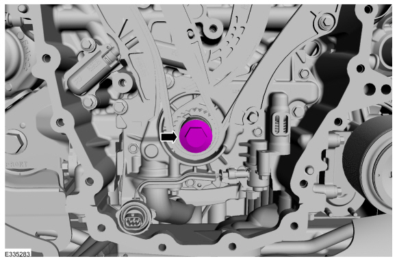
Rotate the crankshaft clockwise.
-
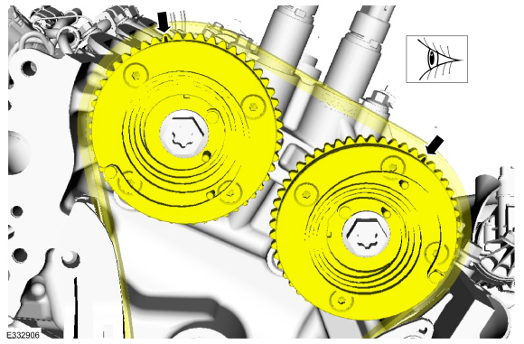
Position the crankshaft sprocket keyway at the 11 o'clock position.
-
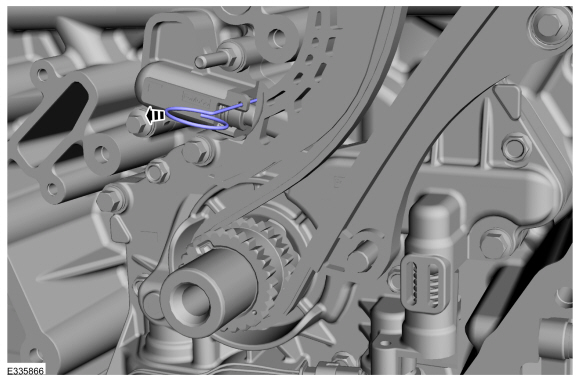
Verify the timing marks on the VCT units are at the positions shown.
-
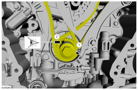
NOTE:
The Camshaft Holding Tool will hold the camshafts in the TDC position.
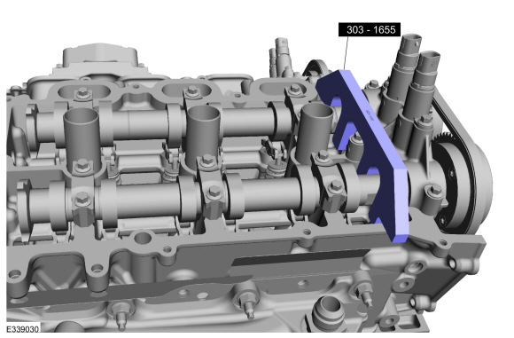
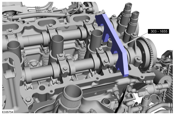
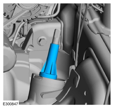
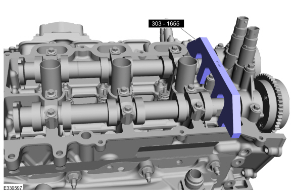
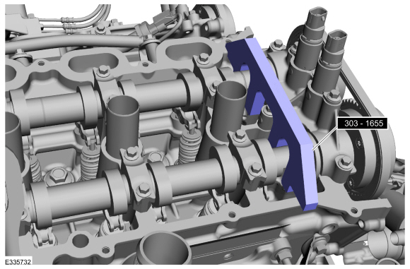
Install Special Service Tool: 303-1655
Tool, Camshaft Holding.
-
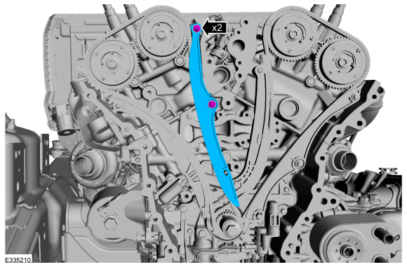
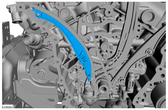
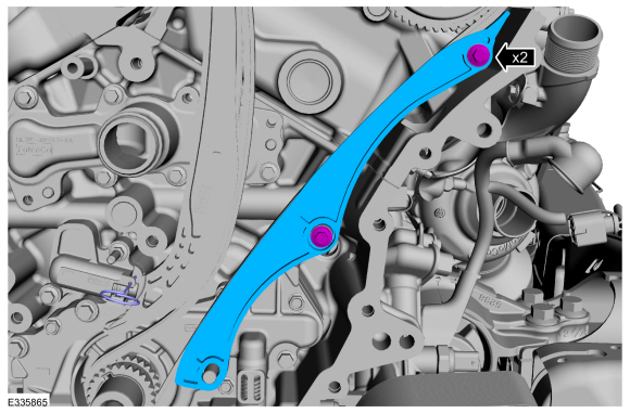
Remove the bolts and the RH timing chain guide.
-
Remove the bolts and the RH timing chain tensioner.
-
Remove the RH timing chain tensioner arm.
-
Remove the RH timing chain.
-
NOTE:
The Camshaft Holding Tool will hold the camshafts in the TDC position.
Remove Special Service Tool: 303-1655
Tool, Camshaft Holding.
-
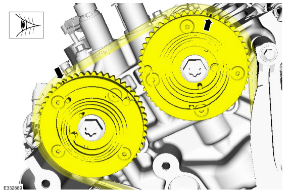
Verify the timing marks on the VCT units are at the positions shown.
-
NOTE:
The Camshaft Holding Tool will hold the camshafts in the TDC position.
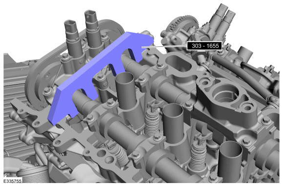
Install Special Service Tool: 303-1655
Tool, Camshaft Holding.
-
Remove the bolts and the LH timing chain guide.
-
Remove the studbolt, bolt and the LH timing chain tensioner.
-
Remove the LH timing chain tensioner arm.
-
Remove the LH timing chain.
-
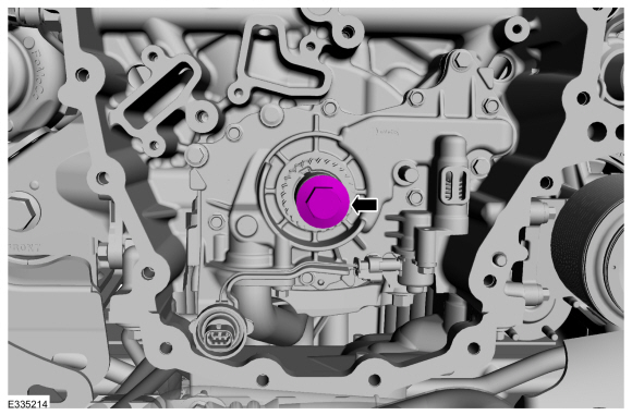
Remove the crankshaft pulley bolt.
-
Remove the timing chain sprocket.
-
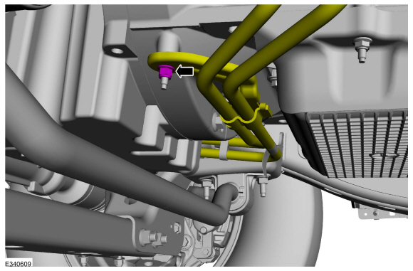
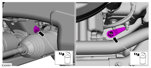
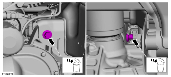
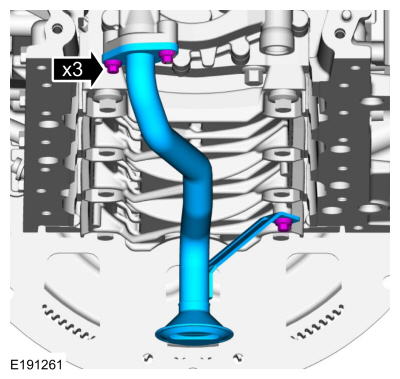
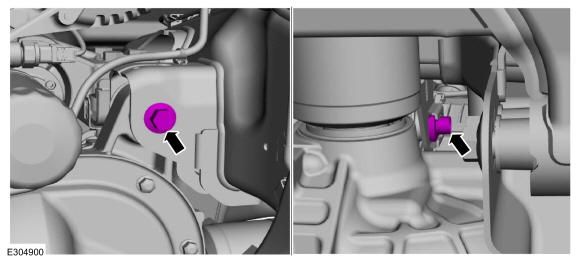
Remove the nut and position the cooler tubes aside.
-
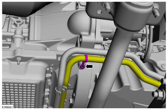
Remove the pin-type retainer and position the cooler tube out.
-
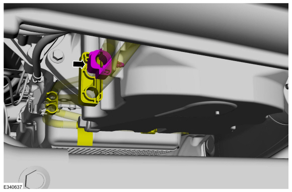
.Remove the pin-type retainer and position the cooler tubes from the oil pan.
-
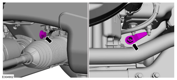
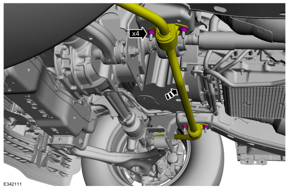
Remove the nuts, bolts and the crossmember.
-
Remove and discard the nuts, allow the sway bar to swing downward.
4x4
-
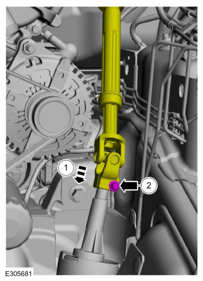
Using a holding device, hold the steering wheel in the straight-ahead position.
-
-
 WARNING:
Install a new steering column shaft bolt.
Reuse could result in bolt failure and loss of vehicle control. Failure
to follow this instruction may result in serious injury to vehicle
occupant(s).
WARNING:
Install a new steering column shaft bolt.
Reuse could result in bolt failure and loss of vehicle control. Failure
to follow this instruction may result in serious injury to vehicle
occupant(s).
Remove and discard the steering column shaft bolt.
-
Separate the steering column shaft U-joint from the steering gear.
-
Remove the steering gear boot.
-
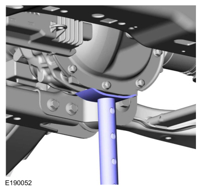
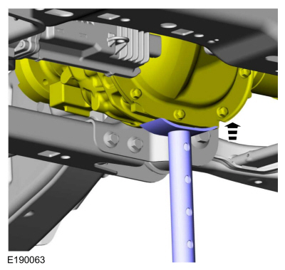
Using an adjustable stand, support the front axle.
Use the General Equipment: Vehicle/Axle Stands
-
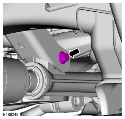
Remove and discard the lower front axle carrier mounting bushing bolt.
-
Remove and discard the axle shaft housing carrier bushing nut and the bolt.
-
NOTE:
After loosening the bolt, it may be necessary to
reposition the axle assembly to prevent interference with the steering
components when removing the bolt.
Remove and discard the upper front axle carrier mounting bushing nut and the bolt.
-
Using an adjustable stand, lower the axle to allow clearance for the oil pan to be removed.
Use the General Equipment: Vehicle/Axle Stands
4x2/4x4
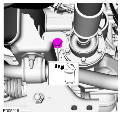
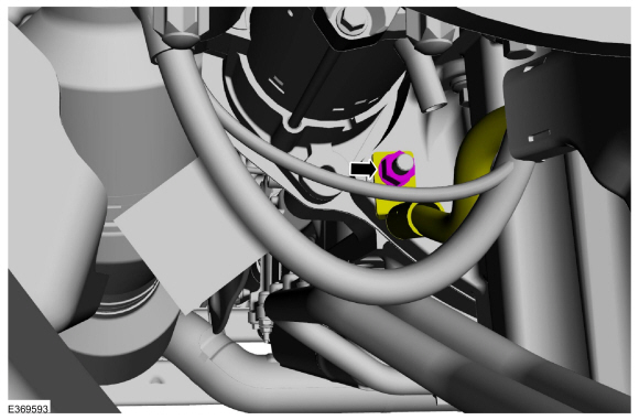
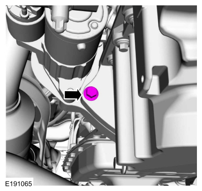
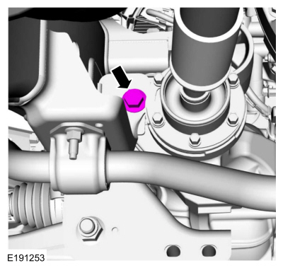
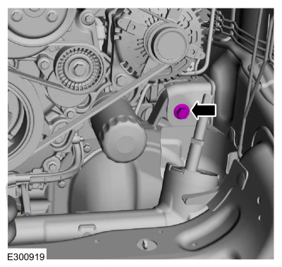
-
Remove the nut and position the ground wire.
-
Remove the oil pan stud.
-
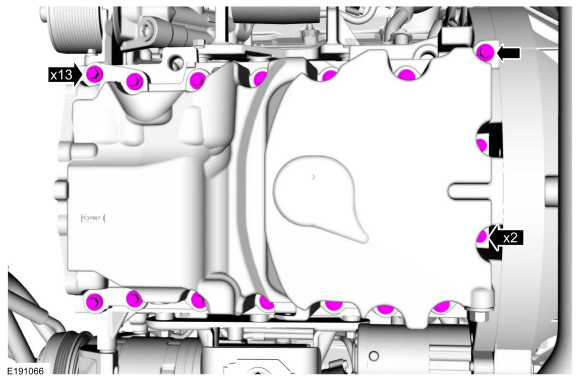
Remove the oil pan bolts.
-
NOTE:
The generator wiring harness retainer is being removed for clearance to install the oil pan.
Detach the generator wiring harness retainer from the engine block.
-
Remove the oil pan bolts.
-
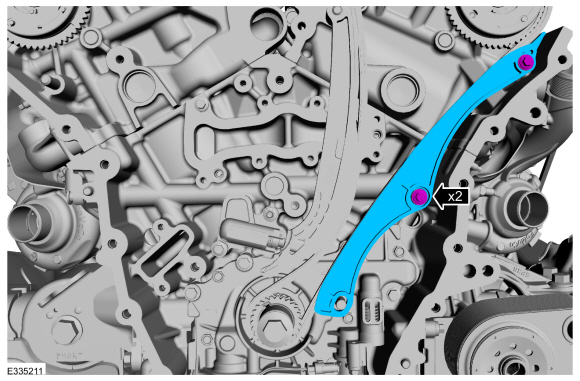
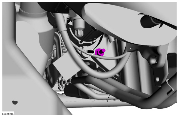
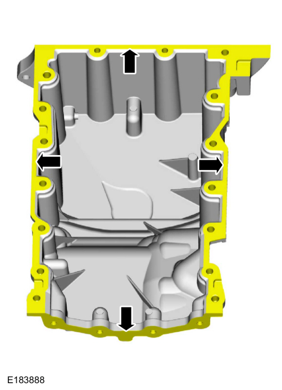
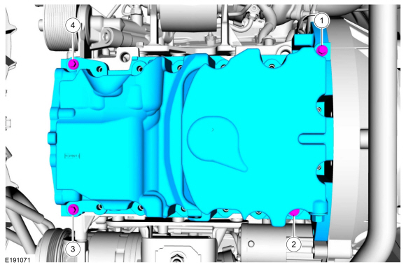
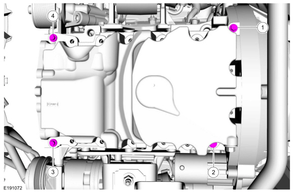
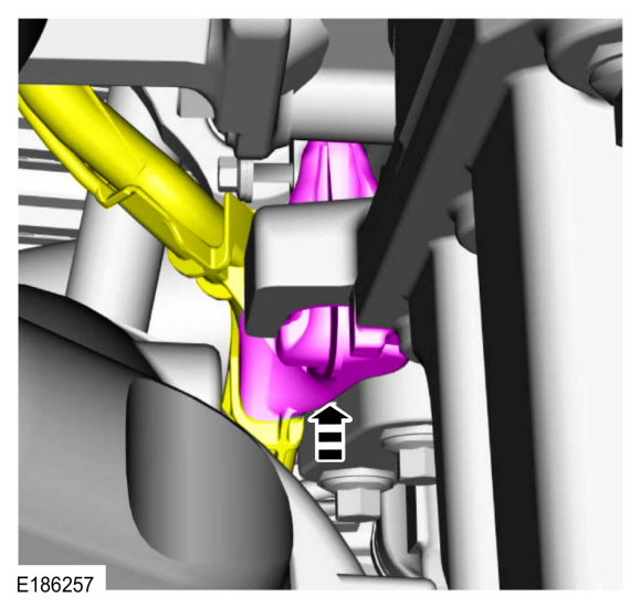
Using a pry tool on the pry pads shown, remove the oil pan.
-
Clean and prepare the RTV sealing surface.
Refer to: RTV Sealing Surface Cleaning and Preparation (303-00 Engine System - General Information, General Procedures).
-
Clean and prepare the RTV sealing surface.
Refer to: RTV Sealing Surface Cleaning and Preparation (303-00 Engine System - General Information, General Procedures).
-
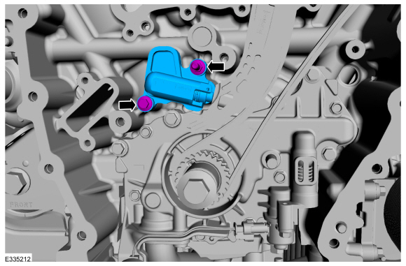
Remove the bolts and oil pump screen and pickup tube.
-
Remove and discard the oil pump screen and pickup tube O-ring seal.
-
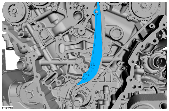
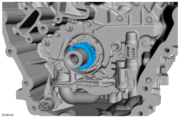
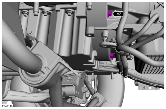
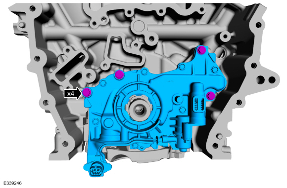
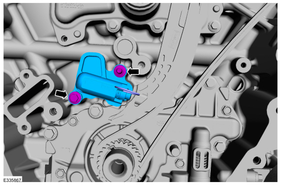
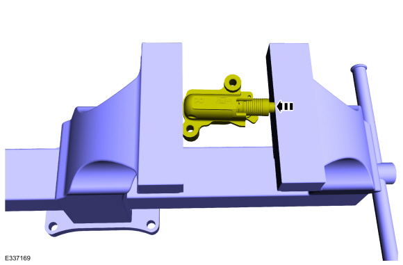
Remove the bolts and oil pump.
Installation
4x2/4x4
-
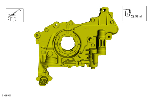
Prime the oil pump. Add 2 tablespoons of clean engine oil to the oil pump and rotate the oil pump by hand.
Refer to: Specifications (303-01)
.
-
Install the oil pump and the bolts.
Torque:
89 lb.in (10 Nm)
-
Install a new oil pump screen and pickup tube O-ring seal.
-
Install the oil pump screen and pickup tube and the bolts.
Torque:
89 lb.in (10 Nm)
-
NOTE:
The oil pan and the specified bolts must be
installed and the oil pan aligned to the cylinder block within 4 minutes
of sealant application. Final tightening of the oil pan bolts must be
carried out within 60 minutes of sealant application.
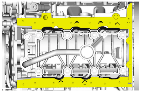
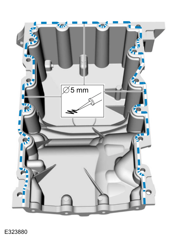
Apply a 5 mm (0.20 in) bead of Motorcraft® High
Performance Engine RTV Silicone to the sealing surface of the oil pan.
Material: Motorcraft® High Performance Engine RTV Silicone
/ TA-357
(WSE-M4G323-A6)
-
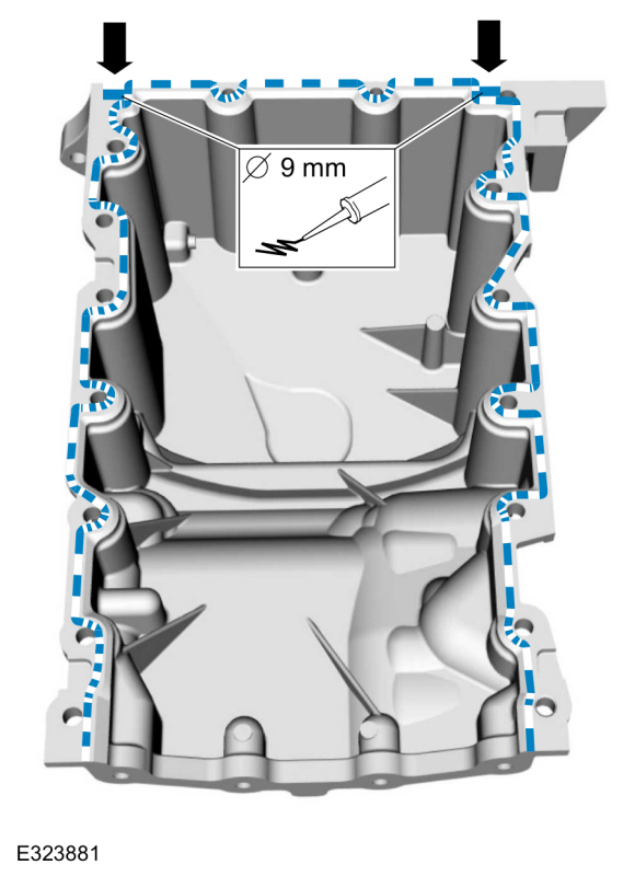
Apply a 9 mm (0.35 in) bead of Motorcraft® High
Performance Engine RTV Silicone to the 2 crankshaft seal retainer
plate-to-cylinder block joint areas on the sealing surface of the oil
pan.
Material: Motorcraft® High Performance Engine RTV Silicone
/ TA-357
(WSE-M4G323-A6)
-
NOTE:
The oil pan and the specified bolts must be
installed within 4 minutes of the start of sealant application.
NOTE:
Keep the oil pan as close as possible to the
transmission while installing, then slide forward towards the engine
front cover to prevent wiping off of the sealant.
Install the bolts finger tight.
-
NOTE:
Do not torque at this time.
Install the bolts finger tight.
-
NOTE:
Do not torque at this time.
Install the stud finger tight.
-
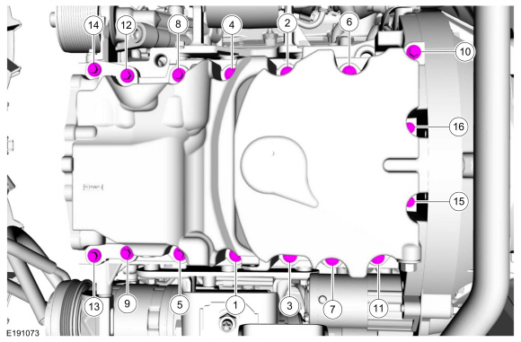
Tighten the oil pan bolts in sequence.
Torque:
27 lb.in (3 Nm)
-
Install the remaining oil pan bolts and tighten in sequence.
Torque:
Stage 1:
Tighten bolts 1-9 and 11-14 to :
177 lb.in (20 Nm)
Stage 2:
Tighten bolt 1-9 and 11-14 additional :
45°
Stage 3:
Tighten bolt 10 to :
177 lb.in (20 Nm)
Stage 4:
Tighten bolt 10 an additional :
45°
Stage 5:
Tighten bolts 15 and 16 to :
89 lb.in (10 Nm)
Stage 6:
Tighten bolts 15 and 16 an additional :
90°
-
Tighten the oil pan bolts.
Torque:
35 lb.ft (48 Nm)
-
Position the ground wire and install the nut.
Torque:
44 lb.in (5 Nm)
-
Tighten the oil pan bolt.
Torque:
35 lb.ft (48 Nm)
-
Attach the generator wiring harness retainer to the engine block.
4x4
-
NOTICE:
Use care when positioning the front axle housing
or the vacuum lines to the axle solenoid may become disconnected or
damaged.
Using an adjustable stand, raise the front axle carrier into position.
Use the General Equipment: Vehicle/Axle Stands
-
NOTE:
It may be necessary to reposition the axle
assembly to prevent interference with the steering components when
installing the bolt.
Install the new upper front axle carrier mounting bushing nut and the bolt finger tight.
-
Install the new axle shaft housing carrier bushing nut and the bolt finger tight.
-
Install the new lower front axle carrier mounting bushing bolt.
Torque:
129 lb.ft (175 Nm)
-
Tighten the axle shaft housing carrier bushing bolt.
Torque:
129 lb.ft (175 Nm)
-
Tighten the upper front axle carrier mounting bushing bolt.
Torque:
129 lb.ft (175 Nm)
-
Remove the adjustable stand.
Use the General Equipment: Vehicle/Axle Stands
-
Install the steering gear boot.
-
-
Position back the steering column shaft U-joint to the steering gear.
-
WARNING:
Install a new steering column shaft bolt.
Reuse could result in bolt failure and loss of vehicle control. Failure
to follow this instruction may result in serious injury to vehicle
occupant(s).
Install a new steering column shaft bolt.
Torque:
22 lb.ft (30 Nm)
-
Remove the holding device from the steering wheel.
4x2/4x4
-
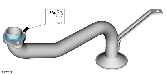
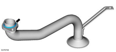
Position the cooler tubes to the oil pan and install the pin-type retainer.
-
Position the cooler tube back and install the pin-type retainer.
-
Position the cooler tubes back and install the nut.
Torque:
124 lb.in (14 Nm)
-
Position the sway bar back and install the nuts.
Torque:
41 lb.ft (55 Nm)
-
Position the crossmember, install the nuts and bolts.
Torque:
66 lb.ft (90 Nm)
-
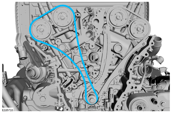
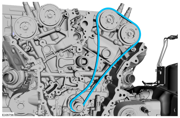
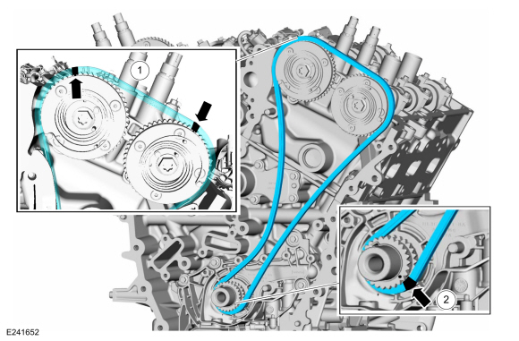
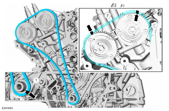
Install the timing chain sprocket.
-
NOTE:
The crankshaft sprocket is reversible with a
timing mark on each face. For installation of each timing chain, utilize
the timing mark on the front face of the crankshaft sprocket for chain
alignment.
-
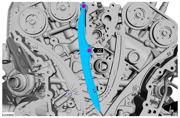
Install the LH timing chain with the single colored links aligned with the timing marks on the VCT units.
-
Install the double colored links so they straddle the timing mark on the crankshaft sprocket.
-
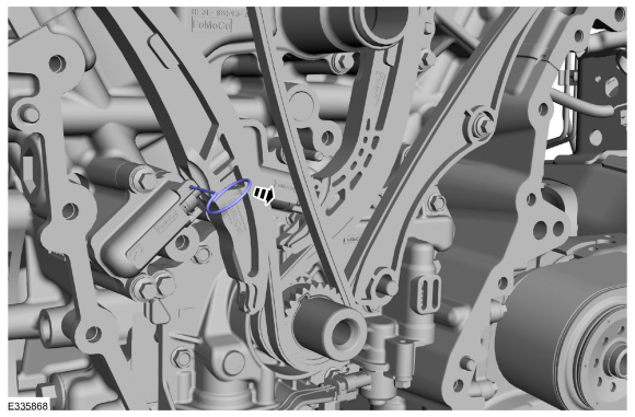
Install the LH timing chain tensioner arm.
-
Position the tensioner in a soft-jawed vise.
-
NOTE:
Use of a commercially available tools with a
curved radius in the range of 10mm - 15mm is suggested for use in
resetting the ratchet clip. Examples are a 8mm closed end wrench,
12x12mm piece of bar stock, T40 to T50 Torx screwdriver or 3/8 wobble
style socket extender.
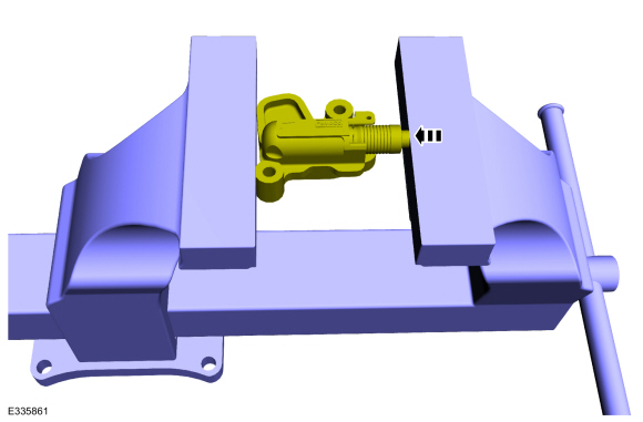
Using a commercially available wrench, push down on the ratchet clip so the ratchet clip pushes outward.
-
-
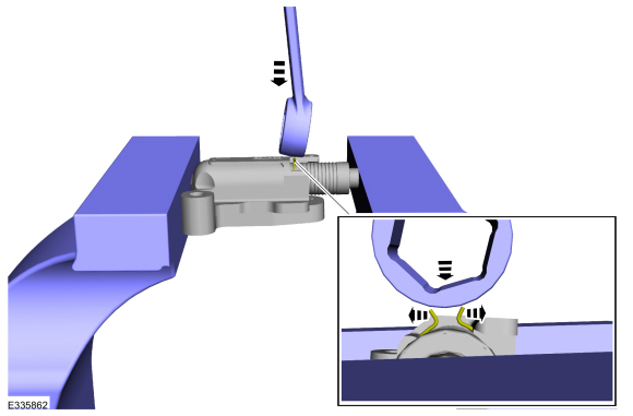
Using the soft-jawed vise, compress the piston to the reset position.
-
Install a locking pin in the 2 holes of the tensioner body to hold the piston in place.
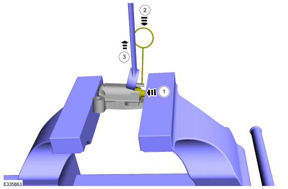
-
Remove the commercially available tool and the tensioner.
-
Position the LH timing chain tensioner with the end of the tensioner
correctly engaged to the tensioner arm and install the fasteners.
Torque:
89 lb.in (10 Nm)
-
Install the LH timing chain guide and bolts.
Torque:
Stage 1:
89 lb.in (10 Nm)
Stage 2:
30°
-
Remove the tensioner pins.
-
Remove Special Service Tool: 303-1655
Tool, Camshaft Holding.
-
Install Special Service Tool: 303-1655
Tool, Camshaft Holding.
-
NOTE:
The crankshaft sprocket is reversible with a
timing mark on each face. For installation of each timing chain, utilize
the timing mark on the front face of the crankshaft sprocket for chain
alignment.
-
Install the RH timing chain with the single colored links aligned with the timing marks on the VCT units.
-
Install the double colored links so they straddle the timing mark on the crankshaft sprocket.
-
Install the RH timing chain tensioner arm.
-
Position the tensioner in a soft-jawed vise.
-
NOTE:
Use of a commercially available tools with a
curved radius in the range of 10mm - 15mm is suggested for use in
resetting the ratchet clip. Examples are a 8mm closed end wrench,
12x12mm piece of bar stock, T40 to T50 Torx screwdriver or 3/8 wobble
style socket extender.
Using a commercially available wrench, push down on the ratchet clip so the ratchet clip pushes outward.
-
-
Using the soft-jawed vise, compress the piston to the reset position.
-
Install a locking pin in the 2 holes of the tensioner body to hold the piston in place.
-
Remove the commercially available tool and the tensioner.
-
Position the RH timing chain tensioner with the end of the tensioner
correctly engaged to the tensioner arm and install the fasteners.
Torque:
89 lb.in (10 Nm)
-
Install the RH timing chain guide and bolts.
Torque:
89 lb.in (10 Nm)
-
Remove the tensioner pins.
-
Remove Special Service Tool: 303-1655
Tool, Camshaft Holding.
-
Install the engine front cover.
Refer to: Engine Front Cover (303-01 Engine - 3.5L EcoBoost (272kW/370PS), Removal and Installation).
Special Tool(s) /
General Equipment
303-1633Remover, Roller Rocker FollowerTKIT-2014D-ROW3TKIT-2014D-FL_ROW
303-1633-01Remover, Roller Rocker Follower
Removal
NOTE:
This procedure should be used when removing and replacing
the clipped roller finger follower or hydraulic lash adjuster and the
camshafts are not removed...
Other information:
Special Tool(s) /
General Equipment
Flat Headed Screw Driver
Transmission Jack
Cable Ties
Tire Lever
Removal
WARNING:
Do not apply heat or flame to the shock absorber or strut
tube. The shock absorber and strut tube are gas pressurized and could
explode if heated...
System Operation
Programmable Module Installation (PMI)
PMI is a diagnostic scan tool process which configures settings in a new module. Data used for the PMI
process is automatically downloaded from the original module and
stored when a diagnostic scan tool session is started...


 Rocker Arm. Removal and Installation